Structural studies of electrochemically activated glassy carbon electrode Effects of chloride anion
正极材料综述

Recent progress in cathode materials research for advanced lithium ion batteries Bo Xu,Danna Qian,Ziying Wang,Ying Shirley Meng*Department of NanoEngineering,University of California San Diego,La Jolla,CA92093,USAContents1.Introduction (51)yered compounds LiMO2 (52)3.Spinel compounds LiM2O4 (56)4.Olivine compounds LiMPO4 (57)5.Silicate compounds Li2MSiO4 (59)6.Tavorite compounds LiMPO4F (62)7.Borate compounds LiMBO3 (63)8.Conclusion (64)Acknowledgements (64)References (64)1.IntroductionWith the worldwide energy shortage being one of the mountingproblems in21st century,efforts have been made to replace thenon-renewable fossil fuels by other green energy sources,such assolar,wind,and hydroelectric power.Different from the conven-tional fossil fuels,most of these green energy sources suffer fromtheir uncontrollable and intermittent nature,therefore thedifficulty in energy storage and regulation results in larger cost.This brings in enormous amount of research interests in materialdevelopments for energy storage.The LIB system is regarded as oneof the near-term solutions because of its high energy density andrelatively simple reaction mechanism.Current LIB technology iswell developed for the portable electronic devices and has beenwidely used in the past twenty years.However,to be implementedin the large-scale high-power system such as the plug-in hybridelectric vehicle(PHEV)or plug-in electric vehicle(PEV),perfor-mance requirements are raised especially from the aspects ofenergy/power density,cycling life and safety issues,thereforefurther LIB material and system developments are necessary.The basic working principles of LIB are shown in Fig.1.A lithiumion battery can work as the energy storage device by convertingelectric energy into electrochemical energy.There are three keycomponents in a LIB system:cathode,anode and electrolyte.Fortoday’s commercialized LIB system,both cathode and anodematerials are intercalation materials.The transition metal oxidesin cathode(graphite in anode)consist of a largely unchangeablehost with specific sites for Li ions to be intercalated in.All Li ionsMaterials Science and Engineering R73(2012)51–65A R T I C L E I N F OArticle history:Available online5June2012A B S T R A C TNew and improved materials for energy storage are urgently required to make more efficient use of ourfinite supply of fossil fuels,and to enable the effective use of renewable energy sources.Lithium ionbatteries(LIB)are a key resource for mobile energy,and one of the most promising solutions forenvironment-friendly transportation such as plug-in hybrid electric vehicles(PHEVs).Among the threekey components(cathode,anode and electrolyte)of LIB,cathode material is usually the most expensiveone with highest weight in the battery,which justifies the intense research focus on this electrode.In thisreview,we present an overview of the breakthroughs in the past decade in developing high energy highpower cathode materials for lithium ion batteries.Materials from six structural groups(layered oxides,spinel oxides,olivine compounds,silicate compounds,tavorite compounds,and borate compounds)arecovered.We focus on their electrochemical performances and the related fundamental crystalstructures,solid-state physics and chemistry are covered.The effect of modifications on both chemistryand morphology are discussed as well.ß2012Elsevier B.V.All rights reserved.*Corresponding author.E-mail address:shirleymeng@(Y.S.Meng).Contents lists available at SciVerse ScienceDirectMaterials Science and Engineering Rj ou r n a l h o m e p a g e:w w w.e l s e v i e r.co m/l oc a t e/m s e r0927-796X/$–see front matterß2012Elsevier B.V.All rights reserved./10.1016/j.mser.2012.05.003are in the cathode sides initially and the battery system is assembled in ‘‘discharged’’status.While charging,Li ions are extracted from the cathode host,solvate into and move through the non-aqueous electrolyte,and intercalate into the anode host.Meanwhile,electrons also move from cathode to anode through the outside current collectors forming an electric circuit.The chemical potential of Li is much higher in the anode than in the cathode,thus the electric energy is stored in the form of (electro)chemical energy.Such process is reversed when the battery is discharging where the electrochemical energy is released in the form of electric energy.The cathode region and anode region are separated by the separator,a micro-porous membrane that allows the electrolyte to penetrate and prevent shorting between the two electrodes.The electrolyte should be ionically conducting and electronically insulating in principle,however the actual properties of the electrolyte is much more complicated.During the first cycle,a so-called solid–electrolyte-interphase (SEI)layer will be formed on the surface of electrodes due to the decomposition of organic electrolyte at extreme voltage range (typically <1.2V or >4.6V).In current LIB technology,the cell voltage and capacities are mainly determined by the cathode material that is also the limiting factor for Li transportation rate.The developments of cathode materials therefore become ex-tremely crucial and receive much attention in recent decade.Since 1980when the LiCoO 2was demonstrated firstly as a possible cathode material for rechargeable lithium battery [1],the transition metal intercalation oxides have caught the major research interests as the LIB cathodes [2–8].Categorized by structure,the conventional cathode materials include layered compounds LiMO 2(M =Co,Ni,Mn,etc.),spinel compounds LiM 2O 4(M =Mn,etc.),and olivine compounds LiMPO 4(M =Fe,Mn,Ni,Co,etc.).Most of the researches are performed on these materials and their derivatives.New structure intercalation materials such as silicates,borates and tavorites are also gaining increasing attentions in recent years.During the materials optimization and development,following designing criterions are often considered:(1)energy density;(2)rate capability;(3)cycling performance;(4)safety;(5)cost.The energy density is determined by the material’s reversible capacity and operating voltage,which are mostly determined by the material intrinsic chemistry such as the effective redox couples and maximum lithium concentration in active materials.For rate capability and cycling performances,electronic and ionic mobilities are key determining factors,though particle morphologies are also important factors due to the anisotropic nature of the structures and are even playing a crucial role in some cases.Therefore materials optimizations are usually made from two important aspects,to change the intrinsic chemistry and to modify the morphology (surface property,particle size,etc.)of the materials.Fig.2compares the gravimetricenergy densities of different cathode materials that are currently under investigations.While some materials such as LiFeBO 3and LiFeSO 4F are already approaching their theoretical energy densi-ties,for other materials including conventional layered and spinel compounds,significant gaps are still present between their theoretical and practical energy densities.The materials with promising theoretical properties have high potentials as the candidates of future generation LIB cathode,therefore are under intensive studies.For certain materials such as the LiFePO 4olivine,significant property improvements have been achieved during the past decade with assistance of newly developed technologies.To review and summarize those researches could provide inspiring perspectives for further material optimizations.In this review,we will discuss the recent research progress in the past decade of different cathode materials following the structural category,and modifications on both chemistry and morphology will be discussed.yered compounds LiMO 2The ideal structure of layered compound LiMO 2is demonstrat-ed in Fig.3.The oxygen anions (omitted for clarity in the figures)form a close-packed fcc lattice with cations located in the 6-coordinated octahedral crystal site.The MO 2slabs and Li layers are stacked alternatively.Although the conventional layered oxide LiCoO 2has been commercialized as the LIB cathode for twenty years,it can only deliver about 140mAh/g capacity which is half of its theoretical capacity.Such limitation can be attributed to the intrinsic structural instability of the material when more thanhalfFig.1.Working principles of LIB(charging).Fig.2.Theoretical and practical gravimetric energy densities of different cathodematerials.Fig.3.Crystal structure of layered LiMO 2(blue:transition metal ions;red:Li ions).(For interpretation of the references to color in this figure legend,the reader is referred to the web version of the article.)B.Xu et al./Materials Science and Engineering R 73(2012)51–6552of the Li ions are extracted.On the other hand,the presence of toxic and expensive Co ions in LiCoO 2has introduced the environmental problem as well as raised the cost of the LIB.The research focusing on layered compounds,therefore have moved from LiCoO 2to its derivatives in which Co ions are partially/fully substituted by more abundant and environmental friendly transition metal ions,such as Ni and Mn.The approaches include mixing the LiNiO 2and LiMnO 2with 1:1ratio,forming layered LiNi 0.5Mn 0.5O 2,and the formation of Li–Co–Ni–Mn–O layered compound (so-called NMC type materials).Good electrochemical data of LiNi 0.5Mn 0.5O 2was firstly reported in 2001by Ohzuku et al.[9].Fig.4shows the typical electrochemical performance of LiNi 0.5Mn 0.5O 2[10,11].The charge/discharge voltages of this material are around 3.6–4.3V where Ni 2+/Ni 4+act as the redox couple as confirmed from in situ X-ray absorption spectroscopy (XAS)study [12].Various methods including X-ray and neutron diffraction,nuclear magnetic reso-nance (NMR)spectroscopy,transmission electron microscope (TEM)and first-principles calculations [13–18]have been per-formed to investigate the structural change and local cation distribution of this material.The results showed that different from classic layered material composed of pure Li layer and pure MO 2slab,8–10%Ni ions are usually found in the Li layer of LiNi 0.5Mn 0.5O 2synthesized by solid state or sol–gel synthesis methods.It was suggested that such Li–Ni interlayer mixing might be partially reduced under high voltage (>4.6V)[19,20].For the transition metal layer,a flower-like in-plane cation ordering that Li in transition metal layer is surrounded sequentially by Mn rings and Ni rings was suggested by first-principles calculations [16]and confirmed by experiments [14,15].With MO 2slabs pined together by the Ni in Li layer,larger reversible capacity ($200mAh/g)can be obtained in LiNi 0.5Mn 0.5O 2at low rate (C /20)with little capacity fading even after 100cycles,therefore the energy density can be significantly improved.The material structure is thermally stable until $3008C,above which oxygen release and material decom-position would occur [21].Structural change including migration of transition metal ions to Li layer at high temperature was also reported both experimentally and computationally [21,22].However,with large amount of un-removable Ni in the Li layers blocking Li diffusion pathways,the Li mobility of the materials is negatively affected.The Li diffusion coefficient in LiNi 0.5Mn 0.5O 2is reported to be lower than that in LiCoO 2by one magnitude of order [23],resulting in the low rate capability of LiNi 0.5Mn 0.5O 2.It was also reported by Kang et al.[11]that the Li–Ni exchange is reduced to $4%in LiNi 0.5Mn 0.5O 2synthesized by ion-exchange method,therefore the rate capability can be significantly improved (shown in Fig.4(c)and (d)).Considering the Li–Ni disorder being major factor affecting the material rate capability,attempts to create new compounds of LiCo x Ni y Mn 1Àx Ày O 2are motivated.While good electrochemical performance of LiCo 1/3Ni 1/3Mn 1/3O 2was already reported in 2001by Ohzuku et al.[24],the importance of the series of Li–Co–Ni–Mn–O material is more recognized as the presence of Co ions can help to reduce the amount of defect Ni in Li layer.The LiCo 1/3Ni 1/3Mn 1/3O 2layer compound can be regarded as the solid solution of LiCoO 2,LiNiO 2and LiMnO 2.LiCo 1/3Ni 1/3Mn 1/3O 2deliver similar reversible capacity with LiNi 0.5Mn 0.5O 2.Their voltage profile are also similar in shape,but the operation voltage window of LiCo 1/3Ni 1/3Mn 1/3O 2can be extended to 3.6–4.7V.The material’s typical electrochemical performance is shown in Fig.5[25,26].With additional Co ions existing in the structure,the Li–Ni interlayer mixing can be much reduced to 1–6%[27–32].Though certain superlattice in the transition metal layer could be obtained from computations [33,34],diffraction [28]and NMR study [35],it is suggested that only short-range ordering can be found and Li in transition metal layer is surrounded primarily by Mn ions.The changes of transition metal valence state following cycling were investigated experimentally and computationally [29,30,32,34–36].In general,it is believed that,the transition metal ions are oxidized in sequence of Ni 2+to Ni 3+,Ni 3+to Ni 4+,Co 3+to Co4+Fig.4.Performance of layered LiNi 0.5Mn 0.5O 2:(a)compositional phase diagram,(b)cycling performance [10],(c)rate performance of LiNi 0.5Mn 0.5O 2synthesized by ion-exchange method [11],and (d)rate performance of LiNi 0.5Mn 0.5O 2synthesized by solid state method [11].B.Xu et al./Materials Science and Engineering R 73(2012)51–6553during charging.Mn 4+ions keep unchanged.However,due to the overlap of oxygen 2p band M 3+/4+band,at the end of charging,part of the electrons were also removed from the oxygen ions,causing possible oxygen release at high charging voltages (>4.5V).As shown in Fig.5(c)and (d),with certain morphology modifications,$90%of the capacity can be retained after 200cycles at room temperature and 84%of the capacity can be retained when at a discharge rate as high as 20C [26].The LiCo 1/3Ni 1/3Mn 1/3O 2compound also shows relatively good performance at elevated temperatures.It was reported [25]that more than 80%capacity can be retained at 558C and half of the capacity can still be achieved when the operation temperature is raised to 958C.We also want to point out that the reduced amount Co can be used to achieve the same benefits.It has been shown by Li et al.that as little as 20%Co (LiCo 0.2Ni 0.4Mn 0.4)can lead to excellent electrochemical perfor-mance [37].While the introduction of Co ions into LiNi 0.5Mn 0.5O 2could improve the material stability,the introduction of extra Li ions,on the other hand,could improve the material capacity.A series of Li-rich layered oxides Li[Li 1/3À2x /3Ni x Mn 2/3Àx /3]O 2therefore are created by making a compound between Li 2MnO 3and LiNi 0.5Mn 0.5O 2to achieve higher capacity beyond the limitation of one Li ion per MO 2formula.With excess Li ions introduced,the theoretical capacity of this series of materials can be increased to more than 300mAh/g.The compound Li[Li 1/9Ni 1/3Mn 5/9]O 2is firstly reported by Lu et al.in 2001[17].Different compositions (x =1/6,1/5,1/4,1/3,5/12,etc.)of this series of materials were studied by the same group later and similar electrochemical performances were shown [38].For this series of materials,the pristine samples are solid solutions phase following the layered structure in general,although it was reported that some of the spinel feature might be observed when x !1/3being heated to 6008C [38].The Li–Ni interlayer mixing is usually much smaller than that in LiNi 0.5Mn 0.5O 2.With x increasing,the Li–Ni interlayer mixing also increases while the c/a ratio decreases.The structuredetails and cation ordering were investigated by diffraction,TEM,NMR spectroscopy and first-principles calculations [39–44].The results show that the excess Li ions were located in the transition metal layer,surrounded mostly by 5or 6Mn 4+ions.The Ni/Mn zigzag ordering is regarded as another competent driving force for the in-plane cation ordering,and actual material may reflect a combination of these two orderings [39].A typical voltage profile of Li[Li 1/9Ni 1/3Mn 5/9]O 2for the first cycle charging is shown in Fig.6(c)[45].It is composed of a slopy region from the open circuit voltage to $4.5V followed by a plateau region between 4.5V and 4.6V.Such plateau,however,does not appear in following cycles causing a large first cycle irreversible capacity.While it is generally agreed that the slopy region originates from the oxidization of Ni 2+to Ni 4+,the mechanism of the anomalous high voltage capacity is still under debate.Several studies [46–48]proposed the mecha-nism of oxygen loss accompanied by Li removal,while other studies proposed the mechanisms involving surface reaction with electrode/electrolyte reduction [49]and/or hydrogen exchange [50].This series of materials deliver the highest reversible capacity (>250mAh/g)for current intercalation cathode materials,but only with low rate (C /50).It was reported that the excess Li ions in transition metal layer are electrochemically active and will migrate to Li layer becoming stable tetrahedral ions during cycling [44,51].Recent study [44]also suggested a possible layer to defective-spinel phase transformation happening near the material surface with significant migration of transition metal ions to lithium layer.These un-removable ions in lithium layer will block the lithium diffusion pathways,therefore may be one of the reasons that cause the low Li chemical diffusion coefficient in the plateau region [43]and the intrinsic poor rate capability of this series of materials.A recent study also suggested that the material rate and temperature performances may also be affected by the particle size as shown in Fig.6[45].For the Li-rich layered compounds,the surface characteristics can significantly affect the material electrochemicalperformanceFig.5.Performance of layered LiCo 1/3Ni 1/3Mn 1/3O 2:(a)compositional phase diagram,(b)cycling performance at elevated temperatures [25],(c)cycling performance at room temperature [26],and (d)rate performance at room temperature [26].B.Xu et al./Materials Science and Engineering R 73(2012)51–6554especially for thefirst-cycle irreversible capacity and rate capability.Different surface modifications,therefore,have been applied to this series of materials as further optimizations. Common coating materials applied include different types of metal oxides(Al2O3,Nb2O5,Ta2O5,ZrO2,and ZnO)[52–54],metal fluorides AlF3[55,56]and other polyanion compounds such as MPO4(M=Al,Co)[57,58].A systematic research on the metal oxides coating was performed by Myung et al.in2007[54].The area-specific impedance(ASI)results showed that during thefirst cycle,the ASI of un-coated samples dramatically increased,while the ASI of all the coated samples hardly changed.The cycling performance and rate capabilities of the materials were improved especially when coated with Al2O3.It was claimed that during the initial cycling,the oxide coating reacted with the electrolyte forming a solid stablefluoride layer which protected the active materials from further HF scavenger.Similar effect was also reported for AlF3coating[56].In addition,the coating can suppress the oxygen loss occurred in the active materials,therefore can also improve the material thermal stability[55,59].The coating morphology is also under optimization.Double layer coating combing two or more coating materials has been developed as well [58].Another approach involves the construction of composition gradient from surface to bulk and forming core–shell structured particles.The structure is shown in Fig.7[60].By introducing composition gradient,the performance of‘‘core’’active materials can be maintained,while the less active‘‘shell’’materials can actasFig.7.Demonstration of core–shell structured particles[60].Fig.6.Performance of layered Li[Li1/3À2x/3Ni x Mn2/3Àx/3]O2:(a)compositional phase diagram,(b)cycling performance(x=1/3)[45],and(c)rate and temperature performance (x=1/3)[45].B.Xu et al./Materials Science and Engineering R73(2012)51–6555a buffer layer and help improve the material performance in surface.Although there are general hypotheses of why the coating materials can improve the active materials’performance,the detailed mechanism is still unknown and under intensive investigations.In summary,the layered oxides LiMO2can deliver high capacities after activation at high voltages,therefore leading to promising energy densities.However,their practical reversible capacities are usually limited by the intrinsic structural instability at low lithium concentrations and high voltages,causing reduced efficiency of the active material utilization.Besides,for the cobalt-free lithium nickel manganese oxides,the intrinsic low rate capability has become the bottleneck problem impeding the commercialization of these materials.3.Spinel compounds LiM2O4The structure of LiM2O4spinel is shown in Fig.8.The oxygen framework of LiM2O4is the same as that of LiMO2layered structure.M cations still occupy the octahedral site but1/4of them are located in the Li layer,leaving1/4of the sites in transition metal layer vacant.Li ions occupy the tetrahedral sites in Li layer thatshare faces with the empty octahedral sites in the transition metal layer.The structure is based on a three-dimensional MO2host and the vacancies in transition metal layer ensure the three-dimensional Li diffusion pathways.The spinel LiMn2O4was proposed as the cathode of the lithium ion battery by Thackeray et al.in1983[61–63],but the material was found to encounter sever capacity fading problem.Two reasons have been considered as the main sources for the capacity fading:(1)dissolution of Mn2+ into the electrolyte generated by the disproportional reaction2 Mn3+!Mn4++Mn2+[64,65]and(2)generation of new phases during cycling and the related micro-strains[64,66].Substituting Mn with other metal ions has been used as an important approach to improve cycling performance of spinel materials.Multiple dopants including inactive ions such as Mg,Al,and Zn[67–69],first row transition metal ions such as Ti,Cr,Fe,Co,Ni,and Cu[70–74] and rare earth metal ions such as Nd and La[75–77]have been investigated and LiNi0.5Mn1.5O4shows the best overall electro-chemical performances among the above.LiNi0.5Mn1.5O4follows the spinel structure of LiMn2O4where Ni ions are located in the sites of Mn ions originally.With different synthesis conditions[78,79],LiNi0.5Mn1.5O4could possess two different structural symmetries,the ordered structure with space group P4332and the disordered structure with space group Fd¯3m. In ordered LiNi0.5Mn1.5O4,Ni ions occupy4b sites and Mn ions occupy12d sites forming an ordered pattern,while in disordered LiNi0.5Mn1.5O4,Ni and Mn ions are randomly distributed in16d sites.In stoichiometric LiNi0.5Mn1.5O4,the valence of Ni ions is2+ pushing all Mn ions to Mn4+.Comparing to LiMn2O4spinel,the redox couple of LiNi0.5Mn1.5O4is switched from Mn3+/Mn4+to Ni2+/ Ni4+and the voltage is lifted from 4.1V to 4.7V.Such high discharge voltage not only enlarges the energy density but also makes the material capable to be coupled with anode materials which have better safety but relatively higher voltage(Li4Ti5O12, etc.).However,phase-pure LiNi0.5Mn1.5O4is difficult to synthesize because impurities such as nickel oxides and/or lithium nickel oxides usually exist[78,80,81].As an alternative approach,the off-stoichiometric material LiNi0.5Mn1.5O4Àx which adopts the disor-dered structure is synthesized and the performances of these two materials are compared in Fig.9[71].InLiNi0.5Mn1.5O4Àx,there are small amount of Mn3+ions exist as the charge compensation of oxygen loss.The small voltage plateau$4V for LiNi0.5Mn1.5O4Àx therefore is attributed to the Mn3+/Mn4+couple.Different from other doped spinel materials the voltage profile of which is usually composed of two distinct plateaus,there is only oneflat plateauatFig.9.Performance of high voltage spinel LiNi0.5Mn1.5O4[71].Fig.8.Crystal structure of spinel LiM2O4(blue:transition metal ions;red:Li ions).(For interpretation of the references to color in thisfigure legend,the reader isreferred to the web version of the article.)B.Xu et al./Materials Science and Engineering R73(2012)51–6556$4.7V for LiNi0.5Mn1.5O4,although in LiNi0.5Mn1.5O4Àx,a small voltage step appears at half lithium concentration.The theoretical capacity of LiNi0.5Mn1.5O4is calculated as147mAh/g,and more than140mAh/g reversible capacity can be obtained experimen-tally.With most of the Mn ions keeping Mn4+unchanged during cycling,both ordered and disordered LiNi0.5Mn1.5O4exhibit good cycling performance for lower rate capability that there is little capacity fading after50cycles in room temperature(Fig.9(a)and (c))and elevated temperature(Fig.9(e)).However,their rate capabilities still need to be improved.The disordered LiNi0.5Mn1.5O4Àx shows better rate capability than ordered LiNi0.5Mn1.5O4for the material electronic conductivity is enhanced with the small amount of Mn3+ions.The ionic conductivity is regarded as another rate-limiting factor.The Li diffusion coefficient of LiNi0.5Mn1.5O4was reported to in a wide range between 10À10cm2/s and10À16cm2/s depending on different compositions and material morphologies[82–84].As a further optimization approach,doping small amount of metal ions into LiNi0.5Mn1.5O4forming‘‘bi-doped’’spinel has been widely used,and certain properties of LiNi0.5Mn1.5O4can be further improved.A recent review paper by Yi et al.[85]has summarized the effect of different doping ions including both cation substitu-tion and anion substitution.By doping other transition metal ions such as Fe,Cr,and Ti into ordered LiNi0.5Mn1.5O4,the impurity phases may be limited and the cation disorder could be enhanced [86–90].It was also reported that dopant such as Co and Cu may enhance the material electronic conductivity and/or lithium diffusion coefficient[91,92].These enhancements therefore could further improve the material cycling performance and rate capability(Fig.10[92]).The doped bivalence metal ions such as Cumay also shift the4.7V plateau to even higher voltage therefore could further improve the energy density.However,for most of the dopants,the high voltage capacity is shortened and the overall reversible capacity is reduced.It was reported[86,92,93]that some doped ions such as Fe,Cu,Al,and Mg tend to occupy the tetrahedral sites and become inactive ions,not only reducing the capacity but also blocking the lithium diffusion pathways,therefore may impose a negative effect to the material performances.Apart from chemistry modification,size minimization is also reported as an effective approach to improve the material rate capability.Highly crystalline LiNi0.5Mn1.5O4nano-sized particles can be successfully synthesized through different methods [79,94,95].It was shown that the bulk properties of nano-sized particles are generally the same compared to micro-sized particles, although their surface areas increase causing increasing surface reactions.However,the small size shortened the Li diffusion length inside the active materials thus largely enhanced the material ionic conductivity.The rate capability of the nano-sized LiNi0.5Mn1.5O4 therefore is highly improved as an overall effect[95,96].It is important to point out the volumetric energy density(Wh/L) suffers from the size minimization greatly as most of the nano-sized materials do not have the optimized packing scheme yet.In summary,the high voltage spinel material is promising due to its high energy density,perfect structural stability and good cycling performance under certain material modifications.The high voltage,however,is out of the voltage window of the current electrolyte,therefore causes the electrolyte decomposition and the formation of unstable SEI on composite cathode side during cycling.It is important to point out that the reversible capacity of this material is currently limited to0.5Li per MO2formula,which although is similar to the practical capacity of LiCoO2,still is significantly lower comparing to the lithium nickel manganese layered compounds.4.Olivine compounds LiMPO4Despite the early works back in1980s[97,98],intensive studies on polyanion materials have not been conducted until recent fifteen years.These materials are receiving growing attentions because of the inherent stability of the polyanion group,which can delay or minimize the oxygen loss happening in traditional layer and spinel oxides.Among all polyanion materials,olivine LiFePO4attracts the most interests due to its excellent electrochemical properties,as well as its low cost,non-toxicity,excellent thermal stability and environment friendliness.It wasfirst found by Goodenough and coworkers in1997[99,100].The structure of LiFePO4is shown in Fig.11.It contains slightly distorted hcp anion oxygen arrays with half of the octahedral sites occupied by Fe and one eighth by Li.The LiO6octahedra are edge-shared while the FeO6octahedra are corner-shared.Both of the LiO6and FeO6run parallel to the c axis and they alternate in the b direction.The a–c planes containing the Li atoms are bridged by PO4tetrahedral.Three different paths of Li diffusion were proposed[101,102]and computational studies suggested that the one along b axis is much more favored than other paths across the channels[101,102].In addition,in2008 Yamada et al.further confirmed from experiments that the Li ion diffusion path along the(010)is a curved one dimensionchainFig.11.Crystal structure of olivine LiMPO4(blue:transition metal ions;yellow:P ions;red Li ions).(For interpretation of the references to color in thisfigure legend, the reader is referred to the web version of thearticle.)Fig.10.Rate performance of rate capability of LiNi x Cu y Mn2ÀxÀy O4[92].B.Xu et al./Materials Science and Engineering R73(2012)51–6557。
J.Electrochem.Soc.-2002-MacNeil-A1332-6
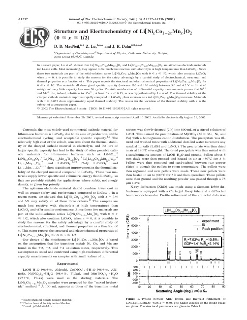
Structure and Electrochemistry of Li†Ni x Co1À2x Mn x‡O2…0рxр1Õ2…D.D.MacNeil,a,*Z.Lu,b,**and J.R.Dahn a,b,**,za Department of Chemistry andb Department of Physics,Dalhousie University,Halifax,Nova Scotia B3H3J5,CanadaIn a recent paper,Lu et al.showed that Li͓Ni0.25Co0.5Mn0.25͔O2and Li͓Ni0.375Co0.25Mn0.375͔O2are attractive electrode materials for Li-ion cells.Most interesting,they appear to be much less reactive with electrolyte at high temperatures than LiCoO2.Since these two materials are part of the solid-solution series Li͓Ni x Co1Ϫ2x Mn x͔O2with0рxр1/2,which also contains LiCoO2 when xϭ0,it is possible to study the reasons for the safety advantage by a careful study of electrochemical,structural,and thermal properties as a function of x.This paper reports the structural and electrochemical properties of Li͓Ni x Co1Ϫ2x Mn x͔O2for 0рxр1/2.The materials all show good specific capacity͑between110and130mAh/g between3.0and4.2V vs.Li at40 mA/g͒and very little capacity loss over50cycles.Careful consideration of differential capacity measurements proves that Ni2ϩand Mn4ϩdo,indeed,substitute for Co3ϩ,at least for xϽ0.15,as was hypothesized by Lu et al.The thermal stability of the charged cathode materials improves rapidly compared to LiCoO2,then saturates as x in Li͓Ni x Co1Ϫ2x Mn x͔O2increases.Materials with xу0.075show approximately equal thermal stability.The reason for the variation of the thermal stability with x is the subject of a companion paper.©2002The Electrochemical Society.͓DOI:10.1149/1.1505633͔All rights reserved.Manuscript submitted November26,2001;revised manuscript received April102002.Available electronicallyAugust21,2002.Currently,the most widely used commercial cathode material forlithium-ion batteries is LiCoO2due to its ease of production,stable electrochemical cycling,and acceptable specific capacity.1,2The relatively high cost of the cobalt,concerns about the thermal stabil-ity of the charged cathode material in electrolyte,and the lure of larger specific capacity has lead to the study of other possible cath-ode materials for lithium-ion batteries such as LiNiO2,3LiNi0.8Co0.2O2,4Li͓Ni(1Ϫx)Mg x/2Ti x/2͔O2,5Li͓Li0.2Cr0.4Mn0.4͔O2,6 Li1ϩx Mn2Ϫx O4,7and LiFePO4.8-10Only LiFePO49andLi1ϩx Mn2Ϫx O411,12show significant improvement in the thermal sta-bility of the charged material compared to LiCoO2.These two ma-terials supply lower specific and volumetric energy than LiCoO2,so they are probably suitable for applications where safety,not energy density,is given top priority.The optimum electrode material should combine lower cost aswell as greater safety and performance compared to LiCoO2.In arecent paper,we showed that Li͓Ni x Co1Ϫ2x Mn x͔O2with xϭ1/4 and3/8may satisfy all of these three criteria.13The samples are much less reactive with electrolyte at high temperatures than LiCoO2and offer similar performance.Since these two materials are part of the solid-solution series Li͓Ni x Co1Ϫ2x Mn x͔O2with0рx р1/2,which also contains LiCoO2when xϭ0,it is possible to study the reasons for the safety advantage by a careful study of electrochemical,structural,and thermal properties as a function of x.This paper reports the structural and electrochemical properties of Li͓Ni x Co1Ϫ2x Mn x͔O2for0рxр1/2.Our choice of the stoichiometry Li͓Ni x Co1Ϫ2x Mn x͔O2is based on the assumption that the transition metals Ni,Co,and Mn are found in theϩ2,ϩ3,andϩ4oxidation states,respectively.This assumption is tested and confirmed using high-resolution differential capacity measurements on samples with small values of x.ExperimentalLiOH•H2O͑98ϩ%,Aldrich͒,Co(NO3)2•6H2O͑98ϩ%,Ald-rich͒,Ni(NO3)2•6H2O͑98ϩ%,Fluka͒,and Mn(NO3)2•4H2O (97ϩ%,Fluka͒were used as the starting materials.The LiNi x Co1Ϫ2x Mn x O2samples were prepared by the‘‘mixed hydrox-ide’’method.13A100mL aqueous solution of the transition metal nitrates was slowly dripped͑2h͒into800mL of a stirred solution of LiOH.This caused the precipitation of M͑OH͒2͑MϭMn,Ni,and Co͒with a homogenous cation distribution.The precipitate wasfil-tered and washed twice with additional distilled water to remove any residual Li salts͑LiOH and LiNO3͒.The precipitate was then dried in air at180°C overnight.The dried precipitate was then mixed with a stoichoimetric amount of LiOH•H2O and ground.Pellets about5 mm thick were then pressed and heated in air at480°C for3h. Pellets were then removed and sandwiched between two copper plates to quench the pellets to room temperature.The pellets were then reground and new pellets were made.These new pellets were then heated in air to900°C for3h and then quenched.These pellets were then ground and the resulting powder was passed through a75m sieve.X-ray diffraction͑XRD͒was made using a Siemens D500dif-fractometer equipped with a Cu target X-ray tube and a diffracted beam monochromator.Profile refinement of the collected data was*Electrochemical Society Student Member. **Electrochemical Society Active Member. z E-mail:jeff.dahn@dal.caFigure 1.Typical powder XRD profile and Rietveld refinement ofLiNi x Co1Ϫ2x Mn x O2with xϭ0.30.The Miller indexes of the Bragg peaksare given.The structural parameters are given in Table I.0013-4651/2002/149͑10͒/A1332/5/$7.00©The Electrochemical Society,Inc.made using Hill and Howard’s version of the Rietveld Program,Rietica.14The electrodes were prepared by combining 7mass %,each of Super S Carbon Black ͑MMM Carbon,Belgium ͒and polyvi-nylidene difluoride ͓PVDF,10%in N -methylpyrrolidinone ͑NMP ͒,NRC ͔with the electrode powders.To the mixture an extra portion of NMP was added to form a slurry,which was then mixed for 10min.The slurry was then coated on a piece of thin aluminum foil ͑16m thick ͒.The electrode was then dried overnight in a 110°C oven.The next day 13mm diam disks were punched.The electrochemical cells were prepared in standard 2325coin-cell hardware with a single lithium metal foil used as both the counter and reference electrode.Cells were assembled in an argon-filled glove box,following previously described procedures.12The electrolyte used for analysis was 1M LiPF 6in ethylene carbonate/diethyl carbonate ͑EC/DEC,33/67͒.The cells were then removed from the glove box and placed on the charging system ͑E-One/Moli Energy ͒.The cells were initially charged with a specific current of 5mA/g between 3and 4.4V vs.Li for four charge/discharge cycles.After the initial four cycles the current was increased to 30mAh/g and the cell was cycled between 3and 4.2V vs.Li for an additional 50cycles.After the cycling,the charged cell ͑4.2V ͒was removed and the differential scanning calo-rimeter ͑DSC ͒sample cells prepared in welded stainless steel tubes,as described previously.15Upon cell disassembly in the glove box,the sample was removed from the aluminum current collector and transferred to the sample tube.The tube was sealed with no addi-tional electrolyte or solvent added.The samples were analyzed in the DSC using a temperature scan rate of 5°C/min.Results and DiscussionFigure 1shows a typical XRD pattern of a sample from the LiNi x Co 1Ϫ2x Mn x O 2series with Miller indexes indicated.All peaks are indexed on the ␣-NaFeO 2structure ͑space group:R 3¯m ,no.166͒and Rietveld refinement was performed on the series using this structure.The Li atoms are on 3a sites,the Ni,Mn,and Co atoms are randomly placed on 3b sites,and oxygen atoms are on 6c sites.Since the radius of the Ni 2ϩcation (r Ni 2ϩϭ0.69Å)is close to that of Li ϩ(r Li ϩϭ0.76Å),a small amount of Ni may occupy the 3a Li sites.If this occurs,we assume the same amount of displaced Li atoms will occupy the 3b Ni site.16͑It is important to note that the refinement cannot distinguish which of Ni,Mn,or CoactuallyFigure 2.Change in lattice constants of LiNi x Co 1Ϫ2x Mn x O 2as Co contentchanges.Figure 3.Amount of Ni in the lithium layers of LiNi x Co 1Ϫ2x Mn x O 2as Co content varies.Table I.Rietveld fitting results for LiNi x Co 1À2x Mn x O 2.R wp is the weighted profile agreement factor,GOF is the goodness of fit,and R B is the Bragg intensity agreement factor as described in Ref.14.x a ͑Å͒c ͑Å͒c /a R wp GOF R B 02.8168Ϯ0.000114.0544Ϯ0.0006 4.989510.45 1.57 4.10.0125 2.8173Ϯ0.000114.0667Ϯ0.0006 4.99309.50 1.30 1.80.025 2.8183Ϯ0.000114.0727Ϯ0.0008 4.99339.30 1.20 1.40.05 2.8208Ϯ0.000114.0856Ϯ0.0008 4.99359.41 1.25 1.90.075 2.8242Ϯ0.000114.1043Ϯ0.0012 4.994111.21 1.18 2.70.15 2.8335Ϯ0.000114.1432Ϯ0.0011 4.991411.06 1.15 2.20.225 2.8457Ϯ0.000114.1860Ϯ0.0009 4.985111.28 1.17 2.30.3 2.8549Ϯ0.000114.2161Ϯ0.0006 4.979510.51 1.41 2.10.375 2.8627Ϯ0.000114.2387Ϯ0.0008 4.973910.70 1.60 2.50.45 2.8795Ϯ0.000114.2784Ϯ0.0010 4.95869.67 1.39 1.50.52.8879Ϯ0.000214.2963Ϯ0.00154.950410.761.671.7moves to the Li layer,although we believe Ni is most likely.͒Figure 1shows that the Rietveld fit to the pattern is excellent,suggesting that the structural model is correct.The best-fit structural parameters are shown in Table I for all samples in the LiNi x Co 1Ϫ2x Mn x O 2series.As the concentration of Ni increases,x in LiNi x Co 1Ϫ2x Mn x O 2,there is an increase in both the a axis and the c axis but a decrease in the c /a ratio.This is clearly demonstrated in Fig.2.The increase in unit cell size might be caused by the substitution of the larger Ni 2ϩ(r Ni 2ϩϭ0.69Å)ion for Co 3ϩ(r Co 3ϩϭ0.545Å).10The Mn 4ϩion (r mn 4ϩϭ0.53Å)is about the same size as the Co 3ϩion,so we believe the Ni ion is responsible for the changes observed.In addition,as dem-onstrated by Fig.3,more transition metal atoms ͑probably Ni ͒are found in Li sites ͑3a ͒when the Ni content (x )increases in LiNi x Co 1Ϫ2x Mn x O 2.Figures 4and 5show the voltage vs.specific capacity of Li/LiNi x Co 1Ϫ2x Mn x O 2cells between 3and 4.4V measured using a specific current of 5mA/g.The x ϭ0sample shows very little first-cycle irreversible capacity,while the remaining samples give first-cycle irreversible capacities between 15and 20mAh/g,except for the x ϭ0.5sample which was near 10mAh/g.These irrevers-ible capacity losses are less than 12%of the first charge capacity.All cells give reversible capacities above 150mAh/g over this potential range.Most interesting in Fig.4is the development of capacity below 3.8V as the Ni content increases.Figures 6and 7show the differential capacity vs.potential for Li/LiNi x Co 1Ϫ2x Mn x O 2cells.The large peak near 3.9V for LiCoO 2(x ϭ0)represents the transition between localized and delocalized electron states in the compound.Delmas et al.have shown that this transition is related to an insulator-metal transition as lithium is removed from the structure.17As the Ni and Mn contents increase ͑i.e.,as x increases ͒in LiNi x Co 1Ϫ2x Mn x O 2there is a decrease in theintensity of the peak,at least until x ϭ0.225.As x increases above 0.225,a new peak near 3.75V increases in intensity.It has been previously suggested that the oxidation states of Ni,Co,and Mn are ϩ2,ϩ3,and ϩ4,respectively,in the LiNi x Co 1Ϫ2x Mn x O 2series.Figure 8shows a schematic of the d-electron levels expected in this compound.18The e g and t 2g de-rived bands should split as indicated in the octahedral crystal field.Based on similarities with LiNiO 2,LiCoO 2,and layered LiMnO 2,we expect Mn to be high spin and Ni and Co to be low spin as shown.The d-levels fall relative to the vacuum level as one moves to the right in the periodic table as schematically indicated.19Based on Fig.8it is clear that the electron configuration Mn 4ϩ,Ni 2ϩis energetically preferred compared to Mn 3ϩ,Ni 3ϩ.The long dashed arrow in Fig.8shows the transfer of the Mn 3ϩe g electron to Ni,making Ni 2ϩ.Figure 7shows the development of low potential capacity as the Ni concentration increases.Figure 9shows the low potential region on an expanded scale.By comparison to the differential capacity of LiCoO 2one can identify the low potential capacity due to the Ni atoms.Figure 9indicates by the shaded regions that part of the differential capacity vs.potential that we believe is due to the oxi-dation of the few Ni 2ϩatoms in the materials with x ϭ0.0125,0.025,and 0.05.The shaded regions in Fig.9are for the second charge of Li/LiNi x Co 1Ϫ2x Mn x O 2and Li/LiCoO 2cells.The specific capacity of the shaded regions in Fig.9were measured ͑the shaded area ͒and were plotted against the Ni content in Fig.10.In addition,corresponding areas were measured for the first charge and the sec-ond discharge of the same cells and these are also plotted in Fig.10.If the Ni 2ϩions are being directly oxidized to Ni 4ϩions ͑removing both approximately equal energy e g electrons in Ni 2ϩas shown in Fig.8͒,then we expect a slope of 560mAh/͑g formula unit Ni ͒which is very close to the observed data in Fig.10.Figure 10also shows a line corresponding to one-electron oxidation and it is clear that this line does not describe the data well.Therefore webelieveFigure 4.V oltage vs.capacity of Li/LiNi x Co 1Ϫ2x Mn x O 2cells between 3and 4.4V for x ϭ0to0.15.Figure 5.V oltage vs.capacity of Li/LiNi x Co 1Ϫ2x Mn x O 2cells between 3and 4.4V for x ϭ0.225to0.50.Figure 6.Differential capacity vs.potential for Li/LiNi x Co 1Ϫ2x Mn x O 2cells with x between x ϭ0and0.15.Figure 7.Differential capacity vs.potential for Li/LiNi x Co 1Ϫ2x Mn x O 2cells with x between x ϭ0.225and 0.50.that at low values of x in LiNi x Co 1Ϫ2x Mn x O 2it is the Ni that is being oxidized at the lowest potentials.At higher values of x ,͑say x Ͼ0.1͒we believe the bands of Ni and Co begin to overlap sub-stantially and the Ni-derived capacity cannot be cleanly discerned.The capacity retention ͑capacity vs.cycle number ͒of Li/LiNi x Co 1Ϫ2x Mn x O 2cells between 3.0and 4.2V ͑᭹͒and between 3.0and 4.4V for a few cells ͑᭺͒is shown in Fig.11.The cells were cycled using a specific current of 30mA/g.There is good capacity retention for all samples with x Ͼ0and these show a capacity between 110and 130mAh/g to 4.2V .The capacity can be increased by some 20-30mAh/g by increasing the cutoff voltage to 4.4V .The capacity of the LiCoO 2sample cycled to 4.2V decreases rapidly with increasing cycle number for reasons that we do not understand.It is worth noting that samples of LiCoO 2made by us,using stan-dard solid-state reactions between Li 2Co 3and CoCO 3or Co 3O 4,show excellent cyclability.Thus,we suspect the poor performance of this LiCoO 2sample must be related to the details of its preparation.After the 50charge-discharge samples shown in Fig.11,the cells were charged to 4.2V for DSC testing.The cells were disassembled and DSC samples prepared from the wet electrodes as described in the Experimental section.Figure 12shows the results of the DSC experiments on the charged LiNi x Co 1Ϫ2x Mn x O 2electrodes.As the concentration of Ni and Mn in LiCoO 2increases,the thermal stabil-ity of the charged cathode material in electrolyte increases,even at the small Ni and Mn concentrations of 0.05.For Ni and Mncon-Figure 8.Schematic of d-electron levels in LiNi x Co 1Ϫ2x Mn x O 2.U Cr is the crystal field splitting energy and U ex is the exchangeenergy.Figure 9.Differential capacity vs.potential for Li/LiNi x Co 1Ϫ2x Mn x O 2cells with x ϭ0.0125,0.025,and 0.05͑͒and Li/LiCoO 2cells ͑͒.The shaded regions are the capacity due to the added nickelatoms.Figure 10.The low potential capacity due to Ni atoms ͑area of shaded regions in Fig.9͒plotted vs.x in LiNi x Co 1Ϫ2x Mn x O 2͑x ϭ0.0125,0.025,0.05,and 0.075͒.Figure 11.Capacity vs.cycle number for Li/LiNi x Co 1Ϫ2x Mn x O 2cells.͑᭹,͒cycling performed between 3and 4.2V ,͑᭺,ᮀ͒cycles performed be-tween 3and 4.4V .centrations above 0.05there is an almost 100°increase in the tem-perature of any significant exothermic activity.For Ni and Mn con-centrations of 0.05and above there is no large change in the reactivity of the sample,each having an almost negligible amount of reactivity below the large exothermic peak near 300°C.ConclusionA full series of LiNi x Co 1Ϫ2x Mn x O 2compounds were synthesized by the mixed hydroxide method.These materials were found to beisostructural with LiCoO 2and have Ni 2ϩand Mn 4ϩ1:1substitution for Co 3ϩ.The amount of Ni in the lithium layer increases as the concentration of Ni in LiNi x Co 1Ϫ2x Mn x O 2increases as determined from Rietveld refinement.These materials show a specific capacity between 110and 130mAh/g between 3.0and 4.2V .They show less than 12%irreversible capacity.These new cathodes with x Ͼ0.05show a dramatic increase in the thermal stability of charged elec-trodes in electrolytes.Dalhousie University assisted in meeting the publication costs of this article.References1.T.Nagaura and K.Tozawa,Prog.Batteries Sol.Cells,9,209͑1990͒.2.K.Mizushima,P.C.Jones,P.J.Wiseman,and J.B.Goodenough,Mater.Res.Bull.,15,783͑1980͒.3.W.Li,J.N.Reimers,and J.R.Dahn,Solid State Ionics,67,123͑1993͒.4.I.Saadoune and C.Delmas,J.Solid State Chem.,136,8͑1998͒.5.Y .Gao,M.V .Yakovleva,and W.B.Ebner,Electrochem.Solid-State Lett.,1,117͑1998͒.6.J.M.Paulsen,B.Ammundsen,H.Disilvesto,R.Steiner,and D.Hassell,Abstract 71,The Electrochemical Society Meeting Abstracts,V ol.2000-2,Phoenix,AZ,Oct 22-27,2000.7. E.Ferg,R.J.Gummow,A.Dekock,and M.M.Thackeray,J.Electrochem.Soc.,141,L147͑1994͒.8. A.K.Padhi,K.S.Nanjundaswamy,and J.B.Goodenough,J.Electrochem.Soc.,144,1188͑1997͒.9. A.Yamada,S.C.Chung,and K.Hinokuma,J.Electrochem.Soc.,148,A224͑1997͒.10.H.Huamg,S.C.Yin,and L.F.Nazar,Electrochem.Solid-State Lett.,4,A170͑2001͒.11.U.von Sacken,E.Nodwell,A.Sundher,and J.R.Dahn,J.Power Sources,54,240͑1995͒.12. D.D.MacNeil,Z.Lu,Z.Chen,and J.R.Dahn,J.Power Sources,108,8͑2002͒.13.Z.Lu,D.D.MacNeil,and J.R.Dahn,Electrochem.Solid-State Lett.,4,A200͑2001͒.14.Rietica vl.62,Windows version of Lucas Heights Powder Method;R.J.Hill andC.J.Howard,J.Appl.Crystallogr.,14,149͑1981͒.15. D.D.MacNeil and J.R.Dahn,Thermochim.Acta,386,153͑2002͒.16.R.D.Shannon,Acta Crystallogr.,Sect.A:Cryst.Phys.,Diffr.,Theor.Gen.Crys-tallogr.,32,751͑1976͒.17.M.Menetrier,I.Saadoune,S.Levasseur,and C.Delmas,J.Mater.Chem.,9,1135͑1999͒.18.Y .Gao,K.Myrtle,M.J.Zhang,J.N.Reimers,and J.R.Dahn,Phys.Rev.B,54,16670͑1996͒.19.W.A.Harrison,Electronic Structure and the Physics of the Chemical Bond ,Dover,New York ͑1989͒.Figure 12.DSC of the charged electrode samples in Fig.10after 50cycles at 4.2V .DSC was performed at 5°C/min.。
原位XRD表征富锂锰基正极材料的结构

原位XRD表征富锂锰基正极材料的结构冯波;王璐璘;马琳鸽;卓锦德【摘要】首次利用原位X射线衍射光谱法(XRD)分析了富锂锰基材料在H2气氛下,温度从25℃逐步升至400℃的过程中结构发生的变化,结果表明:富锂锰基材料最终被还原为MnO和单质Co、Ni,过程中并未出现正交相的LiMnO2,这与三方相(空间群R-3m)的LiMn1/3Ni1/3Co1/3O2还原过程一致,但明显不同于单斜相(空间群C2/m)的Li2MnO3被还原为LiMnO2和MnO的情况,验证了富锂锰基材料的结构为单一的三方相,而非单斜相和三方相的复合相.电化学测试表明:均相结构的三方相富锂锰基材料放电比容量在250 mAh/g左右,充放电循环100次后容量保持率在80%以上.准确地表征富锂锰基材料的三方相结构将有助于改进制备工艺,获得循环性能更好的材料.【期刊名称】《电源技术》【年(卷),期】2019(043)007【总页数】3页(P1097-1099)【关键词】原位XRD;还原;富锂锰基材料;三方相【作者】冯波;王璐璘;马琳鸽;卓锦德【作者单位】北京低碳清洁能源研究所,北京102209;北京低碳清洁能源研究所,北京102209;北京低碳清洁能源研究所,北京102209;北京低碳清洁能源研究所,北京102209【正文语种】中文【中图分类】TM912.9富锂锰基材料xLi2MnO3·(1-x)LiMO2(0<x<1,M=Ni,Co,Mn…)的放电比容量和电压平台都比较高(>250 mAh/g,2.0~4.8 V),是一种很有潜力的锂电池正极材料,但较差的充放电循环性能限制了其商业化应用。
富锂锰基材料的循环性能由其物相结构决定,许多研究者利用X射线衍射光谱法(XRD)、透射电子显微镜法(TEM)直接分析该材料的结构[1-3],但至今观点并不一致,主要分为两种:一种认为是单斜相结构(空间群C2/m),另外一种认为是单斜相和三方相(空间群R-3m)形成的固溶体结构。
锂离子电池基础科学问题(Ⅷ)——负极材料

万方数据万方数据万方数据万方数据万方数据万方数据万方数据万方数据锂离子电池基础科学问题(Ⅷ)——负极材料作者:罗飞, 褚赓, 黄杰, 孙洋, 李泓, LUO Fei, CHU Geng, HUANG Jie, SUN Yang, LI Hong作者单位:中国科学院物理研究所,北京,100190刊名:储能科学与技术英文刊名:Energy Storage Science and Technology年,卷(期):2014,3(2)1.Armand M;Murphy D;Broadhead J Materials for Advanced Batteries 19802.Garreau M;Thevenin J;Fekir M On the processes responsible for the degradation of the aluminum lithium electrode used as anode material in lithium aprotic electrolyte batteries 1983(3-4)3.Yazami R;Touzain P A reversible graphite-lithium negative electrode for electrochemical generators 1983(3)4.Tarascon J MorSe6:A new solid-state electrode for secondary lithium batteries 1985(9)5.Scrosati B Non aqueous lithium cells 1981(11)6.Abraham K Ambient temperature secondary lithium batteries using LiA1 lithium insertion anodes 19877.Hrold A Recherches sur les composes d'insertion du graphite 1955(7-8)8.Dey A;Sullivan B The electrochemical decomposition of propylene carbonate on graphite 1970(2)9.SONY Non-aqueous electrolyte secondary cell 198910.Nagaura T;Tozawa K Lithium ion rechargeable battery 199011.Endo M;Kim C;Nishimura K Recent development of carbon materials for Li ion batteries 2000(2)12.Mabuchi A A survey on the carbon anode materials for rechargeable lithiumbatteries 199413.Yamaura J;Ozaki Y;Morita A High voltage,rechargeable lithium batteries using newly-developed carbon for negative electrode material 1993(1)14.Tarascon J M;Armand M Issues and challenges facing rechargeable lithium battefies 2001(6861)15.Van S W;gcrosati B Advances in Lithium-Ion Batteries 200216.Kang B;Ceder G Battery materials for ultrafast charging and diseharging 2009(7235)17.Armand M;Tarascon J M Building better batteries 2008(7179)18.Jansen A;Kahaian A;Kepler K Development of a high-power lithium-ion battery 199919.Smith K;Wang C Y Power and thermal characterization of a lithium-ion battery pack for hybrid-electric vehicles 2006(1)20.Zhang X;Ross P;Kostecki R Diagnostic characterization of high power lithium-ion batteries for use in hybrid electric vehicles 2001(5)21.Zhou H H;Ci L C;Liu C Y Progress in studies of the electrode materials for Li ion batteries 1998(1)22.Hao R R;Fang X Y;Niu S C Chemistry of the Elements (Ⅲ) 199823.Ohzuku T;Ueda A;Yamamoto N Zero-strain insertion material of Li(Li1/3Ti5/3)O4 for rechargeable lithium cells 1995(5)24.Woo K C;Mertwoy H;Fischer J Experimental phase diagram of lithium-intercalated graphite 1983(12)25.Dahn J Phase diagram of LixC6 1991(17)26.Nalamova V;Guerard D;Lelaurain M X-ray investigation of highly saturated Li-graphite intercalation compound 1995(2)27.Feng Z Z;Song S Q Preparation and application of mesophase pitch 201328.Honda H;Yamada Y Meso-carbon microbeads 197329.Xu B;Chen E Intermediate development phase carbon microbeads (MCMB),properties and applications 1996(3)30.Niu Y J;Zhang H G;ZhouA M Non-Ferrous Progress:1996-2005 200731.Choi W C;Byun D;Lee J K Electrochemical characteristics of silver-and nickel-coated synthetic graphite preparedby a gas suspension spray coating method for the anode of lithium secondary batteries 2004(2)32.Lee H Y;Baek J K;Lee S M Effect of earbon coating on elevated temperature performance of graphite as lithium-ion battery anode material 2004(1)33.Tanaka H;Osawa T;Moriyoshi Y Improvement of the anode performance of graphite particles through surface modification in RF thermal plasma 2004(1)34.Guoping W;Bolan Z;Min Y A modified graphite anode with high initial efficiency and excellent cycle life expectation 2005(9)35.Lee J H;Lee S;Paik U Aqueous processing of natural graphite particulates for lithium-ion battery anodes andtheir electrochemical performance 2005(1)36.Yamauchi Y;Hino T;Ohzeki K Gas desorption behavior of graphite anodes used for lithium ion secondary batteries 2005(6)37.Zhao X;Hayner C M;Kung M C In-plane vacancy-enabled high-power Si-graphene composite electrode for lithium-ion batteries 2011(6)38.王广驹世界石墨生产,消费及国际贸易 2006(1)39.Jonker G H Magnetic compounds with perovskite structure Ⅳ conducting and non-conducting compounds 195640.Murphy D;Cava R;Zahurak S Ternary LixTiO2 phases from insertion reactions 198341.Ferg E;Gummow R;De K A Spinel anodes for lithium-ion batteries 1994(11)42.Robertson A;Trevino L;Tukamoto H New inorganic spinel oxides for use as negative electrode materials in future lithium-ion batteries 199943.Peramunage D;Abraham K Preparation of micron-sized Li4Ti5O12 and its electrochemistry in polyacrylonitrile electrolyte-based lithium cells 1998(8)44.Julien C;Massot M;Zaghib K Structural studies of Li4/3Me5/3O4 (Me=Ti,Mn) electrode materials:Local structure and electrochemical aspects 2004(1)45.Scharner S;Weppner W;Schmid B E Evidence of two-phase formation upon lithium insertion into the Li1.33Ti1.67O4 spinel 1999(3)46.Zaghib K;Simoneau M;Armand M Electrochemical study of Li4Ti5O12 as negative electrode for Li-ion polymer rechargeable batteries 199947.Pecharroman C;Amarilla J Thermal evolution of infrared vibrational properties of Li4/3Ti5/3O4 measured by specular reflectance 2000(18)48.Guerfi A;Charest P;Kinoshita K Nano electronically conductive titanium-spinel as lithium ion storage negative electrode 2004(1)49.Gao L;Qiu W;Zhao H L Lithiated titanium complex oxide as negative electrode 2005(1)50.Bach S;Pereira R J;Baffier N Electrochemical properties of sol-gel Li4/3Ti5/3O4 199951.Kavan L;Grtzel M Facile synthesis of nanocrystalline Li4Ti5O12 (spinel) exhibiting fast Li insertion 2002(2)52.Hao Y;Lai Q Y;Liu D Synthesis by citric acid sol-gel method and electrochemical properties of Li4Ti5O12 anode material for lithium-ion battery 2005(2-3)53.王虹微波法制备钛酸锂的方法 200854.白莹一种用于锂二次电池负极材料尖晶石钛酸锂的制各方法 200655.Li J;Tang Z;Zhang Z Controllable formation and electrochemical properties of one-dimensional nanostructured spinel Li4Ti5O12 2005(9)56.杨立一种应用于锂离子电池的钛酸锂负极材料的制备方法中国 200857.Huang S;Wen Z;Zhu X Effects of dopant on the electrochemical performance of Li4Ti5O12 as electrode material for lithium ion batteries 2007(1)58.Tian B;Xiang H;Zhang L Niobium doped lithium titanate as a high rate anode material for Li-ion batteries2010(19)59.Huang Y;Qi Y;Jia D Synthesis and electrochemical properties of spinel Li4Ti5Ol2-xClx anode materials forlithium-ion batteries 2012(5)60.Venkateswarlu M;Chen C;Do J Electrochemical properties of nano-sized Li4Ti5O12 powders synthesized by a sol-gel process and characterized by X-ray absorption spectroscopy 2005(1)61.Cai R;Yu X;Liu X Li4Ti5O12/Sn composite anodes for lithium-ion batteries:Synthesis and electrochemical performance 2010(24)62.Yuan T;Yu X;Cai R Synthesis of pristine and carbon-coated Li4Ti5O12 and their low-temperature electrochemical performance 2010(15)63.Hu X;Lin Z;Yang K Effects of carbon source and carbon content on electrochemical performances of Li4Ti5O12/C prepared by one-step solid-state reaction 2011(14)64.Martha S K;Haik O;Borgel V Li4Ti5O12/LiMnPO4 lithium-ion battery systems for load leveling application 2011(7)65.Huang K L;Wang Z X;Liu S Q Lithium-Ion Battery Technology and Key Principles 200866.Xu K;Wang X Y;Xiao L X Lithium Ion Battery 200267.Wang Q;Li H;Chen L Novel spherical microporous carbon as anode material for Li-ion batteries 200268.Li H;Wang Q;Shi L Nanosized SnSb alloy pinning on hard non-graphitic carbon spherules as anode materials for aLi ion battery 2002(1)69.Hu J;Li H;Huang X Influence of micropore structure on Li-storage capacity in hard carbon spherules 2005(11)70.Fey G T K;Chen C L High-capacity carbons for lithium-ion batteries prepared from rice husk 200171.Yin G P;Zhou D R;Xia B J Preparation of phosphorus-doped carbon and its performance Lithium intercalation2000(4)72.Schnfelder H H;Kitoh K;Nemoto H Nanostructure criteria for lithium intercalation in non-doped and phosphorus-doped hard carbons 1997(2)73.Buiel E;Dahn J Li-insertion in hard carbon anode materials for Li-ionbatteries 1999(1)74.Rosamaria F;Ulrich V S;Dahn J R Studies of lithium intercalation into carbons using nonaqueous electrochemical-cells 1990(7)75.Stevens D;Dahn J The mechanisms of lithium and sodium insertion in carbon materials 2001(8)76.Bonino F;Brutti S;Piana M Structural and electrochemical studies of a hexaphenylbenzene pyrolysed soft carbon as anode material in lithium batteries 2006(17)77.Guo M;Wang J C;Wu L B Study of carbon nanofibers as negative materials for Li-ion batteries 2004(5)78.Sato Y;Kikuchi Y;Kawai T Characteristics of coke carbon modified with mesophase-pitch as a negative electrodefor lithium ion batteries 199979.Yoshio M;Tsumura T;Dimov N Electrochemical behaviors of silicon based anode material 2005(1)i S C Solid lithium-silicon electrode 197681.Sharma R A;Seefurth R N Thermodynamic properties of the lithium-silicon system 1976(12)82.Seefurth R N;Sharma R A Investigation of lithium utilization from a lithium-silicon electrode 1977(8)83.Seefurth R N;Sharma R A Dependence of lithium-silicon electrode potential and lithium utilization on reference electrode location 1980(5)84.Wen C J;Huggins R A Chemical diffusion in intermediate phases in the lithium-silicon system 1981(3)85.Boukamp B A;Lesh G C;Huggins R A All-solid lithium electrodes with mixed-conductor matrix 1981(4)86.Weydanz W J;Wohlfahrt M M;Huggins R A A room temperature study of the binary lithium-silicon and the ternary lithium-chromium-silicon system for use in rechargeable lithium batteries 199987.Gao B;Sinha S;Fleming L Alloy formation in nanostructured silicon 2001(11)88.Li H;Huang X J;Chen L Q A high capacity nano-Si composite anode material for lithium rechargeable batteries 1999(11)89.Li H;Huang X J;Chen L Q The crystal structural evolution of nano-Si anode caused by lithium insertion and extraction at room temperature 2000(1-4)90.Limthongkul P;Jang Y I;Dudney N J Electrochemically-driven solid-state amorphization in lithium-silicon alloys and implications for lithium storage 2003(4)91.Hatchard T D;Dahn J R In situ XRD and electrochemical study of the reaction of lithium with amorphous silicon 2004(6)92.Key B;Bhattacharyya R;Grey C P Real-time NMR investigations of structural changes in silicon electrodes for lithium-ion batteries 2009(26)93.Key B;Morcrette M;Grey C P Pair distribution function analysis and solid State NMR studies of silicon electrodes for lithium ion batteries:Understanding the (De) lithiation mechanisms 2011(3)94.Beaulieu L Y;Hatchard T D;Bonakdarpour A Reaction of Li with alloy thin films studied by in situ AFM 2003(11)95.Baggetto L;Danilov D;Notten P H L Honeycomb-structured silicon:Remarkable morphological changes induced by electrochemical (De)lithiation 2011(13)96.Lee S W;Mcdowell M T;Choi J W Anomalous shape changes of silicon nanopillars by electrochemical lithiation2011(7)97.Lee S W;Mcdowell M T;Berla L A Fracture of crystalline silicon nanopillars during electrochemical lithium insertion 2012(11)98.He Y;Yu X Q;Wang Y H Alumina-coated patterned amorphous silicon as the anode for a lithium-ion battery with high coulombic effficiency 2011(42)99.He Y;Wang Y H;Yu X Q Si-Cu thin film electrode with kirkendall voids structure for lithium-ion batteries2012(12)100.He Y;Yu X Q;Li G Shape evolution of patterned amorphous and polycrystalline silicon microarray thin film electrodes caused by lithium insertion and extraction 2012101.Wang Y;He Y;Xiao R Investigation of crack patterns and cyclic performance of Ti-Si nanocomposite thin film anodes for lithium ion batteries 2012102.Notten P H L;Roozeboom F;Niessen R A H3-D integrated all-solid-state rechargeable batteries 2007(24)103.Baggetto L;Oudenhoven J F M;Van D T On the electrochemistry of an anode stack for all-solid-state 3D-integrated batteries 2009(1)104.Chan C K;Ruffo R;Hong S S Surface chemistry and morphology of the solid electrolyte interphase on silicon nanowire lithium-ion battery anodes 2009(2)105.Zheng J Y;Zheng H;Wang R An investigation on the sold electrolyte interphase of silicon anode for Li-ion batteries through force curve method 2013(6)106.Zhang X W;Patil P K;Wang C S Electrochemical performance of lithium ion battery,nano-silicon-based,disordered carbon composite anodes with different microstructures 2004(2)107.Chan C K;Ruffo R;Hong S S Structural and electrochemical study of the reaction of lithium with silicon nanowires 2009(1)108.Cui L F;Ruffo R;Chan C K Crystalline-amorphous core-shell silicon nanowires for high capacity and high current battery electrodes 2009(1)109.Mcdowell M T;Lee S W;Ryu I Novel size and surface oxide effects in silicon nanowires as lithium battery anodes 2011(9)110.Ryu I;Choi J W;Cui Y Size-dependent fracture of Si nanowire battery anodes 2011(9)111.Xu W L;Vegunta S S S;Flake J C Surface-modified silicon nanowire anodes for lithium-ion batteries 2011(20) 112.Yue L;Wang S Q;Zhao X Y Nano-silicon composites using poly (3,4-ethylenedioxythiophene):Poly (styrenesulfonate) as elastic polymer matrix and carbon source for lithium-ion battery anode 2012(3)113.Zang J L;Zhao Y P Silicon nanowire reinforced by single-walled carbon nanotube and its applications to anti-pulverization electrode in lithium ion battery 2012(1)114.Yoshio M;Wang H Y;Fukuda K Carbon-coated Si as a lithium-ion battery anode material 2002(12)115.Qu J;Li H Q;henry J J Self-aligned Cu-Si core-shell nanowire array as a high-performance anode for Li-ion batteries 2012116.Jia H P;Gao P F;Yang J Novel three-dimensional mesoporous silicon for high power lithium-ion battery anode material 2011(6)117.Yao Y;Mcdowell M T;Ryu I Interconnected silicon hollow nanospheres for lithium-ion battery anodes with long cycle life 2011(7)118.Fu K;Yildiz O;Bhanushali H Aligned carbon nanotube-silicon sheets:A novel nano-architecture for flexiblelithium ion battery electrodes 2013(36)119.Min J H;Bae Y S;Kim J Y Self-organized artificial SEI for improving the cycling ability of silicon-basedbattery anode materials 2013(4)120.Choi N S;Yew K H;Lww K Y Effect of fluoroethylene carbonate additive on interfacial properties of silicon thin-film electrode 2006(2)121.Chakrapani V;Rusli F;Filler M A Quaternary ammonium ionic liquid electrolyte for a silicon nanowire-based lithium ion battery 2011(44)122.Etacheri V;Haik O;Goffer Y Effect of fluoroethylene carbonate (FEC) on the performance and surface chemistry of Si-nanowire Li-ion battery anodes 2011(1)123.Buddie M C High performance silicon nanoparticle anode in fluoroethylene carbonate-based electrolyte for Li-ion batteries 2012(58)124.Profatilova I A;Stock C;Schmitz A Enhanced thermal stability of a lithiated nano-silicon electrode by fluoroethylene carbonate and vinylene carbonate 2013125.Leung K;Rempe S B;Foster M E Modeling electrochemical decomposition of fluoroethylene carbonate on silicon anode surfaces in lithium ion batteries 2014(3)126.Kovalenko I;Zdyrko B;Magasinski A A major constituent of brown algae for use in high-capacity Li-ion batteries 2011(6052)127.Ryou M H;Kim J;Lee I Mussel-inspired adhesive binders for high-performance silicon nanoparticle anodes in lithium-ion batteries 2012(11)128.Li J;Lewis R;Dahn J Sodium carboxymethyl cellulose a potential binder for Si negative electrodes for Li-ion batteries 2007(2)129.Bridel J S;Azais T;Morcrette M Key parameters governing the reversibility of Si/carbon/CMC electrodes for Li-ion batteries 2009(3)130.Mazouzi D;Lestriez B;Roue L Silicon composite electrode with high capacity and long cycle life 2009(11)131.Guo J C;Wang C S A polymer scaffold binder structure for high capacity silicon anode of lithium-ion battery 2010(9)132.Liu W R;Yang M H;Wu H C Enhanced cycle life of Si anode for Li-ion batteries by using modified elastomeric binder 2005(2)133.Park H K;Kong B S;Oh E S Effect of high adhesive polyvinyl alcohol binder on the anodes of lithium ionbatteries 2011(10)134.Magasinski A;Zdyrko B;Kovalenko I Toward efficient binders for Li-ion battery Si-based anodes:Polyacrylic acid 2010(11)135.Yun J B;Soo K J;Tae L K Aphoto-cross-linkable polymeric binder for silicon anodes in lithium ion batteries 2013(31)136.Han Z J;Yabuuchi N;Hashimoto S Cross-linked poly (acrylic acid) with polycarbodiimide as advanced binder for Si/graphite composite negative electrodes in Li-ion batteries 2013(2)137.Koo B;Kim H;Cho Y A highly cross-linked polymeric binder for high-performance silicon negative electrodes in lithium ion batteries 2012(35)138.Bae J;Cha S H;Park J A new polymeric binder for silicon-carbon nanotube composites in lithium ion battery 2013(7)139.Yim C H;Abu L Y;Courtel F M High capacity silicon/graphite composite as anode for lithium-ion batteries using low content amorphous silicon and compatible binders 2013(28)140.Erk C;Brezesinski T;Sommer H Toward silicon anodes for next-generation lithium ion batteries:A comparative performance study of various polymer binders and silicon nanopowders 2013(15)141.Kim J S;Choi W;Cho K Y Effect of polyimide binder on electrochemical characteristics of surface-modified silicon anode for lithium ion batteries 2013142.Li J;Christensen L;Obrovac M Effect of heat treatment on Si electrodes using polyvinylidene fluoride binder 2008(3)143.Kim Y L;Sun Y K;Lee S M Enhanced electrochemical performance of silicon-based anode material by using current collector with modified surface morphology 2008(13)144.Guo J C;Sun A;Wang C S A porous silicon-carbon anode with high overall capacity on carbon fiber current collector 2010(7)145.Choi J Y;Lee D J;Lee Y M Silicon nanofibrils on a flexible current collector for bendable lithium-ion battery anodes 2013(17)146.Hang T;Nara H;Yokoshima T Silicon composite thick film electrodeposited on a nickel micro-nanocones hierarchical structured current collector for lithium batteries 2013147.Luais E;Sakai J;Desploban S Thin and flexible silicon anode based on integrated macroporous silicon film onto electrodeposited copper current collector 2013148.Tang X X;Liu W;Ye B Y Preparation of current collector with blind holes and enhanced cycle performance of silicon-based anode 2013(6)149.Kim H;Han B;Choo J Three-dimensional porous silicon particles for use in high-performance lithium secondary batteries 2008(52)150.Bang B M;Kim H;Song H K Scalable approach to multi-dimensional bulk Si anodes via metal-assisted chemical etching 2011(12)151.Kasavajjula U;Wang C;Appleby A J Nano-and bulk-silicon-based insertion anodes for lithium-ion secondary cells 2007(2)152.Magasinski A;Dixon P;Hertzberg B High-performance lithium-ion anodes using a hierarchical bottom-up approach 2010(4)153.Liu G;Xun S;Vukmirovic N Polymers with tailored electronic structure for high capacity lithium battery electrodes 2011(40)154.Chan C K;Peng H;Liu G High-performance lithium battery anodes using silicon nanowires 2007(1)155.Idota Y;Kubota T;Matsufiti A Tin-based amorphous oxide:A high-capacity lithium-ion-storage material 1997(5317)156.Courtney I A;Dahn J Key factors controlling the reversibility of the reaction of lithium with SnO2 and Sn2BPO6 glass 1997(9)157.Li H;Huang X J;Chen L Q Direct imaging of the passivating film and microstructure of nanometer-scale SnO anodes in lithium rechargeable batteries 1998(6)158.Liu W;Huang X J;Wang Z Studies of stannic oxide as an anode material for lithium-ion batteries 1998(1)159.Li H;Wang Z;Chen L Research on advanced materials for Li-ion batteries 2009(45)160.David M New materials extend Li-ion performance 2006(5)161.Ogisu K R&D activities & results for sony batteries 2005162.索尼公司索尼成功开发3.5 A·h高容量锂离子电池"Nexelion" 2011163.Dahn J;Mar R;Abouzeid A Combinatorial study of Sn1-xCox (0《x《 0.6) and (Sn0 55Co0 45)1-yCy (0《 y《 0 5)alloy negative electrode materials for Li-ion battaries 2006(2)164.Todd A;Mar R;Dahn J Tin-transition metal-carbon systems for lithium-ion battery negative electrodes 2007(6) 165.Ferguson P;Martine M;Dunlap R Structural and electrochemical studies of (SnxCo1-x)60C40 alloys prepared by mechanical attriting 2009(19)166.Ferguson P;Rajora M;Dunlap R(Sn0.5Co0 5)1-yCy alloy negative electrode materials prepared by mechanical attriting 2009(3)167.Ferguson P;ToddA;Dahn J Comparison of mechanically alloyed and sputtered tin-cobalt-carbon as an anode material for lithium-ion batteries 2008(1)168.Hassoun J;Mulas G;Panero S Ternary Sn-Co-C Li-ion battery electrode material prepared by high energy ball milling 2007(8)vela P;Nacimiento F;Ortiz G F Sn-Co-C composites obtained from resorcinol-formaldehyde gel as anodes in lithium-ion batteries 2010(1)170.Liu B;Abouimrane A;Ren Y New anode material based on SiO-SnxCoyCz for lithium batteries 2012(24)171.Zhong X C;Jiang F Q;Xin P A Preparation and electrochemical performance of Sn-Co-C composite as anode material for Li-ion batteries 2009(1)172.Yang S;Li Q;Shen D Influence of Fe on electrochemical performance of SnxCoy/C anode materials 2011(2)173.Shaobin Y;Ding S;Qiang L Synthesis and electrochemical properties of Sno.35-0 5xCoo 35-0 5xZnxCo 3o composite 2010(1)174.YangSB;ShenD;WuXG Effects of Cu on structures and electrochemical properties of Sn-Co/C composite 2012(4)175.Cui W;Wang F;Wang J Nanostructural CoSnC anode prepared by CoSnO3 with improved cyclability for high-performance Li-ion batteries 2011(13)176.Li M Y;Liu C L;Shi M R Nanostructure Sn-Co-C composite lithium ion battery electrode with unique stability and high electrochemical performance 2011(8)177.Xin L;Jing Y X;Hai L Z Synthesis and properties of Sn30Co30C40 ternary alloy anode material for lithium ion battery 2013(7)178.Lee S I;Yoon S;Park C M Reaction mechanism and electrochemical characterization of a Sn-Co-C composite anodefor Li-ion batteries 2008(2)179.Fauteux D;Koksbang R Rechargeable lithium battery anodes:Alternatives to metallic lithium 1993(1)180.Rahner D;Machill S;Schlorb H Intercalation materials for lithium rechargeable batteries 1996181.Besenhard J;Hess M;Komenda P Dimensionally stable Li-alloy electrodes for secondary batteries 1990182.Maxfield M;Jow T;Gould S Composite electrodes containing conducting polymers and Li alloys 1988(2)183.Winter M;Besenhard J O Electrochemical lithiation of tin and tin-based intermetallics and composites 1999(1) 184.Du C W;Chen Y B;Wu M S Advances in lithium-ion battery anode materials for non-carbon 2000185.Wu Y P;Wan C R Study on materials for lithium-ion batteries tin-based negative 1999(3)186.Kepler K D;Vaughey J T;Thackeray M M LixCu6Sn5(0《x《13):An intermetallic insertion electrode for rechargeable lithium batteries 1999(7)187.Mao O;Dunlap R;Dahn J Mechanically alloyed Sn-Fe(-C) powders as anode materials for Li-ion batteries:Ⅰ.TheSn2Fe-C system 1999(2)rcher D;Beaulieu L;Macneil D In situ X-ray study of the electrochemical reaction of Li with η'-Cu6Sn52000(5)189.Li H;Zhu G;Huang X Synthesis and electrochemical performance of dendrite-like nanosized SnSb alloyprepared by co-precipitation in alcohol solution at low temperature 2000(3)190.Kim H;Kim Y J;Kim D Mechanochemical synthesis and electrochemical characteristics of Mg2Sn as an anode material for Li-ion batteries 2001(1)191.Wang L;Kitamura S;Sonoda T Electroplated Sn-Zn alloy electrode for Li secondary batteries 2003(10)192.Yin J;Wada M;Yoshida S New Ag-Sn alloy anode materials for lithium-ion batteries 2003(8)193.Tamura N;Fujimoto M;Kamino M Mechanical stability of Sn-Co alloy anodes for lithium secondary batteries2004(12)194.Wang L;Kitamura S;Obata K Multilayered Sn-Zn-Cu alloy thin-film as negative electrodes for advanced lithium-ion batteries 2005(2)195.Beauleiu L;Hewitt K;Turner R The electrochemical reaction of Li with amorphous Si-Sn alloys 2003(2)196.Besenhard J;Yang J;Winter M Will advanced lithium-alloy anodes have a chance in lithium-ion batteries 1997(1) 197.Yang J;Winter M;Besenhard J Small particle size multiphase Li-alloy anodes for lithium-ionbatteries 1996(1) 198.Mukaibo H;Sumi T;Yokoshima T Electrodeposited Sn-Ni alloy film as a high capacity anode material for lithium-ion secondary batteries 2003(10)199.Photo F Nonaqueous secondary battery 1995200.Photo F Nonaqueous secondary battery 1995201.Goodenough J;Manthiram A;James A Lithium insertion compounds 1988202.Aydinol M;Kohan A;Ceder G Abinitio calculation of the intercalation voltage of lithium-transition-metal oxide electrodes for rechargeable batteries 1997(2)203.三星SDI株式会社用于非水电解液电池的负极活性材料,其制备方法和非水电解液电池 2005204.Song J H;Park H J;Kim K J Electrochemical characteristics of lithium vanadate,Li1+xVO2,new anode materials for lithium ion batteries 2010(18)205.Chang J J Synthesis and electrochemical:Properties of lithium-ion battery anode material Li1+xVO2 2012206.Armstrong A R;Lyness C;Panchmatia P M The lithium intercalation process in the low-voltage lithium battery anode Li1+xV1-xO2 2011(3)207.Chen H;Xiang K X;Hu Z L Synthesis and electrochemical performance of new anode materials Li1.1V0 9O2 forlithium ion batteries 2012(5)208.Choi N S;Kim J S;Yin R Z Electrochemical properties of lithium vanadium oxide as an anode material for lithium-ion battery 2009(2)zzari M;Scrosati B A cyclable lithium organic electrolyte cell based on two intercalation electrodes 1980(3) 210.Dipietro B;Patriarco M;Scrosati B On the use of rocking chair configurations for cyelabte lithium organic electrolyte batteries 1982(2)211.Ktakata H O;Meri T;Koshita N Procedures of the symposium onprimary and secondary lithium batteries 1988212.Poizot P;Laurelle S;Grugeon S Nano-sized ttansition-metal oxides as negative-electrode materials for lithium-ion batteries 2000(6803)213.Debart A;Dupont L;Poizot P A transmission electron microscopy study of the reactivity mechanism of tailor-made CuO particles toward lithium 2001(11)214.Dedryvere R;Laruelle S;Grugeon S Contribution of X-ray photoelectron spectroscopy to the study of the electrochemical reactivity of CoO toward lithium 2004(6)215.Xin C;Naiqing Z;Kening S3d transition-metal oxides as anode micro/nano-materials for lithium ion batteries 2011(10)216.Li H;Richter G;Maier J Reversible formation and decomposition of LiF clusters using transition metal fluorides as precursors and their application in rechargeable Li batteries 2003(9)217.Badway F;Mansour A;Pereira N Structure and electrochemistry of copper fluoride nanocomposites utilizing mixed conducting matrices 2007(17)218.Dbart A;Dupont L;Patrice R Reactivity of transition metal (Co,Ni,Cu) sulphides versus lithium:The intriguing case of the copper sulphide 2006(6)219.Gillot F;Boyanov S;Dupont L Electrochemical reactivity and design of NiP2 negative electrodes for secondary Li-ion batteries 2005(25)220.Pereira N;Dupont L;Tarascon J Electrochemistry of Cu3N with lithium a complex system with parallel processes 2003(9)221.Zhang W M;Wu X L;Hu J S Carbon coated Fe3O4 nanospindles as a superior anode material for lithium-ion batteries 2008(24)222.Rahman M;Chou S L;Zhong C Spray pyrolyzed NiO-C nanocomposite as an anode material for the lithium-ion battery with enhanced capacity retention 2010(40)223.Wang Y;Zhang H J;Lu L Designed functional systems from peapod-like Co@carbon to Co3O4@carbon nanocomposites 2010(8)224.Zhou G;Wang D W;Li F Graphene-wrapped Fe3O4 anode material with improved reversible capacity and cyclicstability for lithium ion batteries 2010(18)225.Wang Y;Zhang L Simple synthesis of CoO-NiO-C anode materials for lithium-ion batteries and investigation on its electrochemical performance 2012226.Zhang P;Guo Z;Kang S Three-dimensional Li2O-NiO-CoO composite thin-film anode with network structure forlithium-ion batteries 2009(1)227.Zhu X J;Guo Z P;Zhang P Highly porous reticular tin-cobalt oxide composite thin film anodes for lithium ion batteries 2009(44)228.Wang C;Wang D;Wang Q Fabrication and lithium storage performance of three-dimensional porous NiO as anode for lithium-ion battery 2010(21)229.Xia Y;Zhang W;Xiao Z Biotemplated fabrication of hierarchically porous NiO/C composite from lotus pollen grains for lithium-ion batteries 2012(18)230.Yu Y;Chen C H;Shi Y A tin-based amorphous oxide composite with a porous,spherical,multideck-cage morphology as a highly reversible anode material for lithium-ion batteries 2007(7)231.Li F;Zou Q Q;Xia Y Y Co-loaded graphitable carbon hollow spheres as anode materials for lithium-ion battery 2008(2)232.Wu Z S;Ren W;Wen L Graphene anchored with Co3O4 nanoparticles as anode of lithium ion batteries with enhanced reversible capacity and cyclic performance 2010(6)引用本文格式:罗飞.褚赓.黄杰.孙洋.李泓.LUO Fei.CHU Geng.HUANG Jie.SUN Yang.LI Hong锂离子电池基础科学问题(Ⅷ)——负。
氧化亚铜的制备与性能
纳米Cu2O作为光催化剂的制备与性能摘要:光催化技术是一项新型的技术,与其他传统的技术相比具有降解完全、高效、价廉、稳定等优点,因而具有良好的应用前景。
氧化亚铜是一种重要的无机化工原料,因其独特的性质而在诸多领域有着广泛的应用,研究纳米氧化亚铜的制备及光催化性能有着深远意义。
关键词::纳米氧化亚铜,光催化,㈠纳米氧化亚铜的制备方法氧化亚铜具有能够便于对反应温度的操作和控制。
优点是不使用溶剂、并且还具有高选择性、高产率、节省能源、合成工艺简单, 制备方法有烧结法刚、电化学法、水热法和多元醇法等。
1烧结法刚烧结法又称为干法,该方法是将固体铜粉与氧化铜粉末预先混合,再送入锻烧炉内加热到1073一1173K密闭反应得到CuZO,其反应式为:CuO+Cu分CuZO 由于这种方法用铜粉作还原剂,与固体氧化铜进行固相反应制得,固相反应存在反应不均匀、不彻底等固有缺点,因而制得的CuZO粉末中往往含有铜和氧化铜杂质,难于去除。
该法制备得到的氧化亚铜粉末不仅纯度较低,而且粉末粒度取决于原料Cu粉和CuO粉的粗细,高温反应后得到的氧化亚铜容易板结、难于分散、劳动强度大、能耗高。
2电化学法电化学法也称电解法,该法具有流程短、成本低、操作简单、产量高、工作环境良好和产品质量高的优点,因而具有很好的工业化前景和比较成熟的生产工艺。
Yan沙6]等用电化学法制备纳米氧化亚铜时,两极分别采用含铜99.9%的铜板和铜片,电解液采用NaCI、NaOH和KZCrO7组成的混合液,在YB17ll型电化学装置中进行,并且比较了在不同的电流密度下所制样品的光催化性能。
采用紫铜板作阳极,铜片作阴极,在含有NaOH的NaCI碱性水溶液中电解金属铜。
从电极反应机理来看,氧化亚铜粉末是通过阳极铜溶解,并发生水解沉淀反应而生成的。
同时研究了电解液组成及其浓度、温度以及电流密度等因素对氧化亚铜产品质量的影响,从而得到了电化学法制备氧化亚铜的优化工艺条件。
溶胶凝胶法制备锂离子电池正极材料_省略__3_Co_1_3_O_2的研究_吴晓燕

在溶胶体系中添加有机络合剂是用来减小三元材料 LiNi1/3Co1/3Mn1/3O2 颗粒尺寸、提高分散度的常用方法。Singh[23]等 用柠檬酸(CA)作为络合剂,研究加入络合剂 CA 的量对 LiNi1/3Co1/3Mn1/3O2 电化学性能的影响,即 CA 与金属离子的摩尔 比值 R 对材料晶格参数和电化学性能的影响。经过研究分析: 当 CA 与金属离子的摩尔比值 R =3 时,所 得 的 材 料 LiNi1/3Co1/3Mn1/3O2 颗粒大小约 200 nm,并且在对其在 4.6~2.5 V 放 电时,其首次循环的库仑效率约为 93%;Zhang 等 [24] 采用酒石 酸作为凝胶络合剂,合成酒石酸和金属离子不同摩尔量比(R) 的前驱体(R =1, 2, 3, 4),并对前驱体进行不同温度煅烧(分别 是 450,700,800,900 ℃),通过研究表明 R =2,煅烧温度为 900 ℃时所得到的三元材料物理和化学性质最好,其中 Ni2+ 与 Li+ 的阳离子混排率为 1.3%,在 2.8~4.4 V 进行充放电时,其首次 放电比容量为 172 mAh/g,库仑效率为 93.4%。Kuthanapillil[25]等 用间苯二酚和甲醛作为络合剂,经煅烧得到 LiNi1/3Co1/3Mn1/3O2 的颗粒大小为 0.5~1 μm,颗粒堆积成孔洞,直径为 1~5 μm,具有较大的比表面积。对材料进行电化学性能研究,100 次循环后,孔洞结构大部分还维持着,充放电电压为 2.5~4.6 V 时,其首次放电比容量为 209 mAh/g,经 220 次循环,放电比 容量为 190 mAh/g,20 C 时的放电比容量为 0.5 C 时的 84%, 具有较好的电化学性能。Zhang[26]等用乙二胺四乙酸和柠檬酸 (EDTA-CA)作为双螯合剂,经煅烧得到多孔三维网状的 LiNi1/3Co1/3Mn1/3O2,颗粒尺寸约为 200 nm。并考察了 EDTA 与金 属离子不同摩尔比值 R(R=0, 1, 2)对材料形貌、尺寸和电化学 性能的影响。经研究,R=1 时材料电化学性能最好,在 1 C 和 10 C 倍率下,其放电比容量分别是 168 和 100 mAh/g,1 C 经
诱导基团参与电化学降解甘蔗渣木质素

能源危机问题已经成为人类所需要面对的重大 难题之一[1]。 木 质 素 作 为 仅 次 于 纤 维 素 的 第 二 大 生物 质 能 源[2],为 植 物 的 生 长 起 支 撑 和 保 护 作 用[3]。研究发 现 木 质 素 是 自 然 界 中 唯 一 一 种 含 有 苯环结构的生物质大分子,其结构单体可以大体分 为三类[4]:愈创 木 基 类 (G)、紫 丁 香 基 类 (S)、对 羟 基苯基类(H)。同时木质素的碳链结构中也有含量 丰 富 的 活 性 基 团,如 羰 基、酯 基。 因 为 具 备 这 些 特 质,所以木质素可以作为生产芳香族及其衍生物的 重要碳源[5]。
Participationofinducedgroupinelectrochemical degradationofbagasselignin
HANXiao,LANChunxing,SHENDayu,LIGang
(SchoolofChemicalEngineeringandTechnology,HebeiUniversityofTechnology,Tianjin300130,China)
究。电话:18222957251,E-mail:2968257097@qq.com
第 10期
韩笑等:诱导基团参与电化学降解甘蔗渣木质素
2317
表面,在 80℃ 温度下用草酸浸泡 2h,然后洗净备 用。配制 1mol/L的稀硫酸溶液,在固定电流密度 下使阳极极化 2~3h,得到 Pb/PbO2阳极。 1.3 电化学诱导木质素降解过程
反应结束后,移取 30mL反应后母液于烧杯中, 然后加入等体积的乙酸乙酯搅拌均匀。用胶头滴管 吸取 0.5mol/L的稀硫酸逐滴滴加,并不断搅拌,调 节 pH值为 2~3时使未反应的木质素残渣完全析 出。将酸析后的悬浮液离心 10min,分离固液。分 离后的固体木质素残渣用去离子水洗涤 4次,洗去 残渣表面的小分子有机物和无机盐类,然后放入真 空干燥箱中干燥。
材料科学与工程专业英语翻译

Unit1:交叉学科交叉学科 interdiscipline 介电常数介电常数 dielectric constant 固体性质固体性质 solid materials 热容热容 heat capacity 力学性质力学性质 mechanical property 电磁辐射电磁辐射 electro-magnetic radiation 材料加工材料加工 processing of materials 弹性模量(模数)elastic coefficient 1.直到最近,科学家才终于了解材料的结构要素与其特性之间的关系。
It was not until relatively recent times times that that scientists came to to understand understand the relationship between the structural elements of materials and their properties . 2.材料工程学主要解决材料的制造问题和材料的应用问题。
Material Material engineering engineering mainly to solve the problem and create material application. 3.材料的加工过程不但决定了材料的结构,同时决定了材料的特征和性能。
Materials processing process is not only to de structure and decided that the material characteristic and performance. 4.材料的力学性能与其所受外力或负荷而导致的形变有关。
Material Material mechanical mechanical properties with the extemal force or in de deformation of the load. Unit2:先进材料先进材料 advanced material 陶瓷材料陶瓷材料 ceramic material 粘土矿物粘土矿物 clay minerals 高性能材料高性能材料 high performance material 合金合金 metal alloys 移植移植 implant to 玻璃纤维玻璃纤维 glass fiber 碳纳米管碳纳米管 carbon nanotub 1、金属元素有许多有利电子,金属材料的许多性质可直接归功于这些电子。
- 1、下载文档前请自行甄别文档内容的完整性,平台不提供额外的编辑、内容补充、找答案等附加服务。
- 2、"仅部分预览"的文档,不可在线预览部分如存在完整性等问题,可反馈申请退款(可完整预览的文档不适用该条件!)。
- 3、如文档侵犯您的权益,请联系客服反馈,我们会尽快为您处理(人工客服工作时间:9:00-18:30)。
Electrochimica Acta52(2007)5907–5913Structural studies of electrochemically activated glassy carbon electrode: Effects of chloride anion on the redox responses of copper deposition Kang Shi a,∗,Kun Hu a,Sheng Wang a,Chung-Yin Lau b,Kwok-Keung Shiu b,∗∗a Department of Chemistry,Xiamen University,Xiamen361005,Chinab Department of Chemistry,Hong Kong Baptist University,Kowloon Tong,Kowloon,Hong Kong,ChinaReceived4December2006;received in revised form8March2007;accepted9March2007Available online19March2007AbstractThe redox behaviors of copper species at electrochemically activated glassy carbon electrodes have been investigated in aqueous solutions containing chloride anions.Experimental results showed that the voltammetric responses of copper species were influenced by the electrochemical activation means employed.Abnormal copper stripping was observed at electrodes obtained by cyclic polarization.Cyclic polarization would cause changes in the interwoven graphitic crystalline surface of glassy carbon,producing electrode interface with low distribution density of electron transfer sites for the early nucleation of metallic copper in the presence of chloride anion.Potentiostatic activation would generate oxygen-containing functionalities and maintain the basic surface structure of graphitic crystalline with high distribution density of electron transfer sites.©2007Elsevier Ltd.All rights reserved.Keywords:Glassy carbon;Electrochemical activation;Surface structure;Copper deposition and stripping;Chloride anions1.IntroductionGlassy carbon electrode is possibly the most used sp2 hybridized carbon composite electrode in electrochemical research.Its bulk has a complex structure of interwoven graphitic ribbons and the basic structural units of nanometer dimensions are planar aromatic structures with basal and edge planes[1–3]. Usually,glassy carbon electrode undergoes pretreatment pro-cess before use in order to obtain reproducible responses[3]. Simple electrochemical activation is considered a better and quicker in situ pretreatment means[4–9],when compared with other pretreatment methods such as laser activation[10–13] and mechanical polishing[14–17].Electrochemically pretreated glassy carbon electrode(PGCE)usually gives reproducible surface,improved electron transfer and specific adsorption behaviors[3,18–20].On the other hand,electrochemical activa-tion might also result in more complex surface structures.Better understanding of the new interfacial structure is necessary and important for its potential applications in manyfields.∗Corresponding author.∗∗Corresponding author.Tel.:+852********;fax:+852********.E-mail address:kkshiu@.hk(K.-K.Shiu).In general,the electrode is electrochemically activated either in basic or acidic(or neutral)rger background cur-rent and higher fraction of oxygen contents have been observed for the electrode pretreated in acidic(or neutral)solutions,and the activated surface has been proposed to be a porous oxi-dized multilayer[4,6,21–23].Raman investigation indicated that electrochemical activation resulted in a high fraction of edge planes and an increasing number of graphitic microcrystalline defects[24].Kinetic studies suggested that electron transfer at the oxidized surface was affected by the electrochemical sur-face structure[1],oxygen-containing functional groups[25], cleanliness[23]and hydrophobicity[26],etc.Two voltammetric methods are usually employed to activate the glassy carbon electrodes.These include the polarization of the electrode at a highly oxidative potential or the application of potential cycling in a wide potential range[19,20,27,28].Several experimental methods have been used to examine the structures of the graphite oxidefilm.Ellipsometric studies showed the growth of a transparent oxidizedfilm when cyclic polarization was employed[29,30].The void fraction of thefilm obtained by potential cycling was estimated to be80%,while the void frac-tion of thefilm obtained by potentiostatic activation was between zero and70%[29,30].Nagaoka et al.[31–38]suggested that electrochemically activated glassy carbon obtained by constant0013-4686/$–see front matter©2007Elsevier Ltd.All rights reserved. doi:10.1016/j.electacta.2007.03.0285908K.Shi et al./Electrochimica Acta52(2007)5907–5913potential oxidation could create micropore structures with the average radius of the surface pores being about10–20˚A.We have previously demonstrated that the surface structures of the PGCE were affected by the activation procedures employed[27]. The average size of the void space developed by potentiostatic activation was larger than those obtained by cyclic polarization in sulfuric acid solution.Adsorption studies showed that the rel-ative sizes of both the adsorbent and the void space had strong influence on the adsorption behaviors of the PGCE[39,40].Metallic copper species often showed good reversible response without under-potential deposition at carbon electrode surface[41–45].The redox processes of copper species were strongly affected by the presence of chloride anions in solu-tion[43,45].As suggested by Miller et al.[46,47],the density of intrinsic active sites for nucleation influenced the processes involved in the electrochemical deposition and stripping of cop-per.When the metallic portion produced by early nucleation was prematurely oxidized to Cu(I)Cl passivation layer during the anodic process,the electro-conductive connection between metallic crystalloid and the electrode would be broken,causing inhibition to the oxidation of metallic crystalloid.Only after the application of a potential positive enough,the oxidation of copper crystalloid would continue[46,47].The fraction and distribution of electro-conductive metallic copper played a key role in the oxidation of the whole metallic copper deposits.The redox behaviors of copper chloride species reflected the differ-ence in the distribution density of electron transfer sites within nanometer range.The presence of low distribution density of electron transfer sites would result in an abnormal oxidation behavior of metallic copper in the presence of chloride anion [46,47].In this report,the PGCE surface was investigated on the basis of the deposition/dissolution reactions of metallic copper,dif-ferent from the soluble electroactive probes employed in most of the previous studies.It has been reported that the nucleation density of metallic copper depositing at the pretreated carbon electrode could be used to quantify the activated properties of carbon electrode surface[41].The early nucleation of metallic copper might reflect the surface complications of the PGCE.The effects of chloride anion on the deposition/dissolution reactions of metallic copper at the PGCE might offer a new way to exam-ine the interfacial characteristics and structures of the PGCE prepared by different procedures.2.ExperimentalCopper(II)chloride,copper(II)sulfate and sodium chloride were obtained from Aldrich,and were used as received.Cop-per(I)chloride solution was freshly prepared by oxidation of highly pure metal copper wire(99.99%)at a constant poten-tial in sodium chloride solution(pH3.0).All chemicals were of reagent grade and were used as received.Reagent solutions were freshly prepared and degassed for5min before use.The pH of the reagent solutions was adjusted by the addition of hydrochloric acid or sodium hydroxide.Deionized water was obtained by purification through a Millipore system and was used throughout.V oltammetric measurements were recorded with a CHI-660A V oltammetric Analyzer(CH Instruments Inc.).A conventional three-electrode cell was employed,incorporating a glassy car-bon working electrode,a saturated calomel reference electrode (SCE)and a platinum foil counter electrode.All potentials were quoted versus the SCE reference.Electrode rotation was con-trolled by a Pine MSRX rotator/controller(Pine Instrument Company).Highly oriented pyrolytic graphite(HOPG)electrode(ZYH grade,Advanced Ceramics)wasfixed on a steel plate with car-bon glue and was resurfaced by peeling away surface layers using adhesive tape before use.Electrochemical measurements were carried out in an electrochemical cell similar to that described by Bowler et al.[48].The electrode area exposing to solution was limited to0.165cm2by a silicone O-ring seal. The edge plane of the same HOPG was sealed by epoxy.An elec-trode area of0.04cm2was exposed to solution through either newly cutting or polishing progressively with0.3m Al2O3 powder.Both glassy carbon voltammetric electrodes and rotating-disc glassy carbon electrodes of5.0mm in diameter were obtained from Tokai Carbon Company.Glassy carbon electrodes were polished progressively withfiner emery paper,then thoroughly with0.3m Al2O3powder on polishing cloth.The working electrode was cleaned in an ultrasonicating bath for1min before used.Two different voltammetric activation methods were employed in0.5M H2SO4solutions.For potentiostatic activa-tion,the glassy carbon electrode was anodized at+2.0V for a short period of time(from0.5to3.0min)and then polarized at−1.0V for1min.The potential was then cycled between +0.8and−0.5V at a scan rate of0.1V/s for two cycles and ended at−0.5V.Cyclic polarization could also be employed for the activation of glassy carbon electrodes.The electrode was cycled between−0.3and+2.0V at0.1V/s for8–10voltammet-ric cycles until stable voltammograms were obtained.3.Results and discussion3.1.Voltammetric responses of copper(II)chloride atPGCE obtained by different pretreatment meansFig.1(a)shows the cyclic voltammogram of polished glassy carbon in0.5mM CuSO4+0.1M Na2SO4(pH3.0).A broad cathodic wave centred at−0.16V was observed.On the reverse scan,a sharp anodic peak appeared at+0.02V.The effects of chloride anion on the redox processes of metal copper deposi-tion at glassy carbon electrodes were investigated.The pH of the test solution was adjusted to3.0in order to avoid possible precip-itation as Cu(OH)1.5Cl0.5[43].Fig.1(b)shows the voltammetric response of polished glassy carbon in a0.5mM CuCl2+0.1M NaCl solution,when cycled between+0.6and−0.6V.Two cathodic peaks were observed at+0.06and−0.32V,and two anodic peaks appeared at−0.09and+0.12V in the follow-ing anodic scan.The voltammetric behaviors were similar to those reported at graphite and gold electrodes[42,46,49]. Three reactions were involved within such potential rangeK.Shi et al./Electrochimica Acta52(2007)5907–59135909Fig.1.V oltammetric responses of glassy carbon electrodes in copper solutions.(a)Polished GCE in0.5mM CuSO4+0.1M Na2SO4(pH3.0);polished GCE(b)and PGCE obtained by potentiostatic activation with anodization time of 10s(c);45s(d);90s(e)in0.5mM CuCl2+0.1M NaCl(pH3.0).Scan rate: 20mV/s.[46]:Cu2++Cl−+e−→CuCl(1) CuCl+Cl−→CuCl2−(2) CuCl+e−→Cu+Cl−(3) When the potential was scanned between+0.6and−0.1V,only thefirst cathodic peak at+0.06V and the second anodic peak at+0.12V were observed.These two redox peaks appeared to be a reversible redox couple,corresponding to the combined reaction involving both reactions(1)and(2)at high chloride ion concentration,and can be expressed as reaction(4)[43,46,50]:Cu2++2Cl−+e−→CuCl2−(4) Copper metallic phase began to deposit at potentials more neg-ative than−0.26V and the corresponding cathodic peak was observed at−0.32V,as shown in Fig.1(b).The deposition pro-cesses might involve many factors including electron transfer kinetics,early nucleation of metal and interfacial structure of electrode[51,52].According to the literature reports[46,50],metallic copper wasfirstly oxidized to the barely conductive CuCl precipitate film in chloride solution,as described by the reverse reac-tion of reaction(3).When the chloride ion concentration was high enough to cause dissolution of the CuClfilm as described by reaction(2),the underneath metallic copper would become exposed and then be continuously oxidized[49,50].The anodic peak observed at−0.09V in the reverse scan was resulted from both reactions(2)and(3).The soluble CuCl2−species pro-duced were subsequently oxidized at more positive potential,Table1V oltammetric responses of glassy carbon electrodes in0.5mM CuCl2+0.1M NaCl(pH3.0)Electrode E pc(1)(V)E pc(2)(V)E pa(3)(V)E pa(4)(V) Polished GCE+0.06−0.32−0.09+0.12 PGCE(potentiostatic activation)10s+0.05−0.31−0.09+0.1345s+0.03−0.32−0.10+0.1490s+0.02−0.32−0.10+0.15 PGCE(cyclic polarization)1cycle+0.05−0.35−0.09+0.12,+0.04 3cycles+0.04−0.36−0.10+0.12,+0.05 9cycles+0.02−0.38−0.11+0.10(IIIa) corresponding to the second anodic peak at+0.12V described by reaction(4).Electrochemically activated glassy carbon electrode(PGCE) obtained by potentiostatic activation was also studied.The extent of activation for PGCE obtained by potentiostatic activation would depend on the anodization time[18–20].In practice, the anodization time used should be less than90s to avoid memory effects and poor reproducibility[19].Curves(c),(d) and(e)of Fig.1show the voltammetric responses of PGCE obtained by potentiostatic activation with different anodization time.The cyclic voltammograms were characterized by two cathodic peaks and two anodic peaks,very similar to those for the polished glassy carbon.The corresponding voltammetric data are tabulated in ually,the peak current increased with increasing extent of activation.This might result from the increases in the actual electrode area and the background current. Similar to those observed for the polished GCE,the peak cur-rent of the second anodic peak at PGCE was always smaller than thefirst anodic peak.Meanwhile,an additional anodic shoulder peak was observed at around zero potential for the PGCE with anodization time longer than45s,as shown in Fig.1(d)and(e).Electrochemical activation of glassy carbon electrodes can also be conducted by cyclic polarization ually, a stable activation voltammogram was resulted after a nine-cycle activation[18,20].Fig.2shows the typical voltammetric responses of PGCE,obtained by cyclic polarization with differ-ent extent of activation,in0.5mM CuCl2+0.1M NaCl solution at pH3.0.The corresponding voltammetric data are also shown in paring with the PGCE obtained by potentio-static activation,deposition of metallic copper occurred at more negative potential when cyclic polarization was employed for electrochemical activation.The peak current for thefirst anodic wave decreased obviously as the extent of activation increased. The most obvious change was that a new anodic peak(IIIa) appeared at around+0.10V.This new anodic peak(IIIa)even overlapped with the redox peak for reaction(4),as shown in Fig.2(c).The electrochemical behaviors were very similar to those observed at nitrogen-incorporated tetrahedral amorphous carbon electrodes(taC:N)reported by Miller and coworkers [46,47].Experimental results shown in Figs.1and2indicated that there were differences in the redox processes of copper and chlo-5910K.Shi et al./Electrochimica Acta52(2007)5907–5913Fig.2.Cyclic voltammograms of PGCE obtained by cyclic polarization with different voltammetric cycles.(a)One cycle;(b)three cycles;(c)nine cycles. Electrolyte:0.5mM CuCl2+0.1M NaCl(pH3.0).Scan rate:20mV/s.ride ions at the electrodes obtained by different pretreatment procedures.Since the solution was of identical composition, the changes in voltammetric behaviors should be related to the difference in the surface characteristics.Different pretreatment means would produce different electroactive surfaces,resulting in different voltammetric responses,especially at higher extent of activation.3.2.Voltammetric responses in copper(I)chloride solutionThe PGCEs prepared by different activation procedures have been found to have different adsorption characteristics [3,18–20].Meanwhile,the newly deposited metal copper phase probably reacted with copper(II)species in solution to form cop-per(I)species[50].The anodic peak(IIIa)nearly overlapped with the redox peaks corresponding to reaction(4).This anodic peak might arise from the oxidation of the preferred accumula-tion of Cu(I)intermediate species at the new surface.The nature of the IIIa peak was investigated in NaCl solution containing Cu(I)Cl2−complex ions so as to limit the presence of copper(II) cations.Fig.3shows the voltammetric responses of PGCE in1mM Cu(I)Cl2−species in0.1M NaCl(pH3.0).When the potential was scanned negatively from zero to−0.6V,metallic copper deposition was observed and a sharp deposition peak was appar-ent at−0.25V at the surface obtained by potentiostatic activation for90s,as shown in Fig.3(a).In the anodic scan,thefirst anodic peak was observed at−0.06V,with a peak current of 139A.The second smaller anodic peak appeared at+0.14V. The reversible cathodic peak was observed at+0.06V.There were no particular differences in the voltammetric responses between Cu(I)and Cu(II)chloride species at PGCE obtained by potentiostaticactivation.Fig.3.Cyclic voltammograms of PGCE in1mM Cu(I)Cl2−+0.1M NaCl(pH 3.0).(a)PGCE obtained by potentiostatic activation of90s;(b)and(c)PGCE obtained by cyclic polarization of nine cycles.Scan rate:20mV/s.Fig.3(b)shows that copper metal started to deposit from −0.27V and the cathodic peak was subsequently observed at −0.38V on the surface obtained by cyclic polarization for ninecycles.In the reverse anodic scan,a very broad anodic peak was observed at around−0.12V and the new anodic peak(IIIa) appeared at+0.11V.However,when the potential was cycled between−0.1and+0.6V,only a couple of redox peaks for reaction(4)was observed at+0.05and+0.14V,as shown in Fig.3(c).Obviously,Cu(I)intermediates did not accumulate at the electrode surface.It indicated that the presence(or absence) of the new anodic peak(IIIa)was dependent on whether metallic copper had been deposited or not.Consequently,the new anodic peak(IIIa)should correspond to an abnormal oxidation process of copper metal deposits at the PGCE prepared by cyclic polar-ization,as compared to the normal oxidation processes observed at polished glassy carbon and metal electrodes.3.3.Redox reactions of copper species at rotating-disc PGCEA rotating-disc electrode(RDE)was employed to study the oxidation peak(IIIa)under slow scan rate to examine whether soluble or precipitate species were involved in the redox pro-cesses.Fig.4(a)shows the voltammogram of rotating-disc glassy carbon electrode,obtained by potentiostatic activation for90s,in a solution containing0.5mM CuCl2+0.1M NaCl (pH3.0).Thefirst cathodic plateau current was observed from +0.03V and the current increased with increasing rotating rate. Metallic copper started to deposit at a potential more negative than−0.25V and a current loop was observed in the reverse scan.On the other hand,metallic copper usually deposited from zero potential at the same RDE in CuSO4+Na2SO4solution,K.Shi et al./Electrochimica Acta52(2007)5907–59135911Fig.4.V oltammetric responses of rotating-disc PGCE obtained by potentio-static activation for90s.(a)0.5mM CuCl2+0.1M NaCl(pH3.0);(b)0.5mM CuSO4+0.05M Na2SO4(pH3.0).Scan rate:5mV/s.Rotating rate:500rpm. as shown in Fig.4(b).It suggested that reduction of CuCl2−anion was involved during the early stage of nucleation.The application of rotating-disc technique at a slow scan rate of 5mV/s significantly improved the mass transport of copper species to the electrode surface.The amount of metallic copper deposits increased significantly,as evidenced by the presence of a thick brown copperfilm at the electrode surface.During the anodic process,thefirst anodic peak appeared at−0.04V, about50mV more positive than that observed in Fig.1(e).No oxidation peak relating to reaction(4)was observed within the potential range examined.The stirring of the rotating-disc elec-trode pushed the CuCl2−anion species away from the electrode surface.Fig.5(a)shows the corresponding voltammogram for the rotating-disc PGCE obtained by cyclic polarization for nine cycles in CuCl2+NaCl solution.Thefirst cathodic plateau cur-rent became apparent at+0.06V,and the deposition of metallic copper occurred at−0.31V.Correspondingly,metallic copper started to deposit from zero potential in CuSO4+Na2SO4solu-tion at the same RDE surface,as shown in Fig.5(b).In the reverse anodic scan,a small shoulder anodic peak appeared at−0.06V, while the broad anodic peak(IIIa)appeared at around+0.10V. Since the soluble CuCl2−species were forced to diffuse away from the RDE surface,the large anodic peak(IIIa)should be resulted from the oxidation of some precipitate species adhering to the rotating electrode surface,consistent with those observed in Fig.3.The above observations indicated that chloride ions were responsible for the abnormal voltammetric behaviors of metallic copper deposition at the PGCE obtained by cyclic polar-ization.Thus,these should be the differences in the interfacial structure,where the early nucleation of copper metal occurs, which cause the abnormal oxidationbehavior.Fig.5.V oltammetric responses of rotating-disc PGCE obtained by cyclic polar-ization for nine cycles.(a)0.5mM CuCl2+0.1M NaCl(pH3.0);(b)0.5mM CuSO4+0.05M Na2SO4(pH3.0).Scan rate:5mV/s.Rotating rate:500rpm.3.4.Redox reactions of copper species at HOPG electrodesAs one type of sp2hybridized carbon,glassy carbon containsboth edge and basal planes.The different PGCE surface struc-tures might be resulted from the difference in the ratios betweenedge planes and basal planes.Highly oriented pyrolytic graphite(HOPG)possesses the simplest structure of sp2hybridized car-bon electrodes.Examination of the voltammetric responses ofthe copper deposition reactions at HOPG electrode might pro-vide useful information for the elucidation of the redox reactionsinvolved,especially for the nature of the anodic peak(IIIa).Fig.6(a)and(b)shows the respective voltammetric responsesof the polished edge plane and the newly resurfaced basal planeof HOPG electrode in1mM CuCl2+0.1M NaCl(pH3.0).Twocathodic peaks and two anodic peaks were observed,similarto those observed at the polished glassy carbon.The redoxwave corresponding to reaction(4)appeared to be reversibleat the edge plane,as shown in Fig.6(a).Copper depositionwas observed at around−0.36V for the edge plane and at −0.39V for the basal plane.In the reverse anodic scan,thefirst anodic peak was observed at−0.06and−0.04V,respectively.No anodic peak(IIIa)appeared at both surfaces.It indicated thatthe anodic peak(IIIa)was not arisen from the difference in theinterfacial characteristics and structures of the two planes.Based on semi-quantitative analysis,the edge plane and thePGCE prepared by potentiostatic activation provided compara-ble characteristics for redox reactions of copper chloride,includ-ing low deposition overpotential,high electron transfer kineticsrate for reaction(4)and normal oxidation process of metal-lic copper deposits.It was consistent with our previous reportthat potentiostatic activation created void space large enoughto expose both the edge planes and the electronically perturbed5912K.Shi et al./Electrochimica Acta52(2007)5907–5913Fig.6.V oltammetric response of HOPG electrodes in1mM CuCl2+0.1M NaCl(pH3.0).(a)Polished edge plane and(b)the newly resurfaced basal plane. Scan rate:20mV/s.basal planes(edge step)in the interior of the graphite oxidefilm [27,39].Interestingly,neither edge nor basal planes offered inter-facial characteristics resembling the PGCE activated by cyclic polarization,especially for the abnormal oxidation behavior.It suggested that there were changes in the fundamental structure of glassy carbon during cyclic polarization.3.5.Effects of surface morphology on the redox behaviorsExperimental results indicated that different voltammetric behaviors were observed at glassy carbon electrodes obtained by different pretreatment processes and were likely related to the difference in the surface characteristics produced by electro-chemical activation.The observation of the abnormal oxidation behavior of metallic copper in the presence of chloride anion for PGCE obtained by cyclic polarization reflected that this type of PGCE interface apparently had the lower distribution den-sity of electron transfer sites for the early nucleation.Cyclic polarization might cause changes in the surface structure of interwoven graphitic crystallites of glassy carbon throughout, while polishing or potentiostatic polarization means did not. Cyclic polarization was considered a weak activation means not able to remove carbon oxide effectively when compared with potentiostatic activation.Oxygen-containing groups pro-duced by cyclic polarization might accumulate at the whole graphitic crystallite surface and penetrate the crystallite to some extent with increasing extent of polarization.The accumulation of oxygen-containing functionalities might cause decreases in the distribution density of electron transfer sites.On the other hand,potentiostatic activation was an extensive erosion means capable of removing the excrescent carbon oxide at the graphitic crystallite surface to create larger void space without changing the basic surface structure of graphitic crystalline.4.ConclusionsIn aqueous solutions containing chloride anions,the redox behaviors of copper species at glassy carbon electrode varied with the interfacial surface prepared by different electrochem-ical activation procedures.Carbon electrodes were exposed to extreme potentials for a longer time when potentiostatic activation was employed.The application of the more neg-ative potential of−1.0V resulted in more effective removal of surface oxides.Potentiostatic activation would generate oxygen-containing functionalities and maintain the basic surface structure of graphitic crystalline with high distribution density of electron transfer sites.On the other hand,cyclic polarization was considered a weak activation means not able to remove car-bon oxide effectively.Cyclic polarization might cause changes in the interwoven graphitic crystalline surface of glassy carbon, producing electrode interface with low distribution density of electron transfer sites for the early nucleation of metallic copper.AcknowledgementsThis work was partially supported by the Research Grants Council of Hong Kong(HKBU2049/01)and the Natural Sci-ence Foundation of Fujian Province,China(E0310006).References[1]G.M.Jenkins,K.Kawamura,Polymeric-Carbons,Carbon Fiber,Glass andCarbon,Cambridge University Press,England,1976.[2]A.Oberlin,in:B.A.Thrower(Ed.),Chemistry and Physics of Carbon,Marcel Dekker,New York,1989.[3]R.L.McCreery,in:A.J.Bard(Ed.),Electroanalytical Chemistry,vol.13,Marcel Dekker,New York,1991.[4]R.J.Bowling,R.T.Packard,R.L.McCreery,J.Am.Chem.Soc.111(1989)1217.[5]R.C.Engstrom,Anal.Chem.54(1982)2310.[6]N.Cenas-Rozgaite,A.Pocius,J.Kulys,J.Electroanal.Chem.154(1983)121.[7]K.K.Shiu,F.Y.Song,H.P.Dai,Electroanalysis8(1996)1160.[8]H.P.Dai,K.K.Shiu,J.Electroanal.Chem.419(1996)7.[9]H.M.Wu,R.P.Riourg,P.Vernereau,J.Electroanal.Chem.162(1984)225.[10]G.E.Cabaniss,A.A.Diamanties,W.R.Murrphy,R.Wlinton,T.J.Meyer,J.Am.Chem.Soc.107(1985)1845.[11]E.Hershenhart,R.L.McCreery,R.D.Knight,Anal.Chem.56(1984)2256.[12]T.G.Strein,A.G.Ewing,Anal.Chem.63(1991)194.[13]N.M.Pontikos,R.L.McCreery,J.Electroanal.Chem.224(1992)229.[14]H.Zhang,L.A.Coury,Anal.Chem.65(1993)1552.[15]G.N.Kamau,W.S.Wills,J.F.Rusling,Anal.Chem.57(1985)545.[16]I.F.Hu,D.H.Karweik,T.Kuwana,J.Electroanal.Chem.188(1985)59.[17]R.M.Wightman,M.R.Deakin,P.M.Kovach,W.G.Kuhr,K.J.Stutts,J.Elechem.Soc.131(1984)1578.[18]K.K.Shiu,K.Shi,Electroanalysis10(1998)959.[19]K.K.Shiu,K.Shi,Electroanalysis12(2000)85.[20]K.Shi,K.K.Shiu,Electroanalysis13(2001)1319.[21]P.K.Upadhyay,J.Electroanal.Chem.271(1989)339.[22]R.L.McCarley,E.A.Irene,R.W.Murray,J.Phys.Chem.95(1991)2492.[23]R.C.Engstrom,V.A.Strasser,Anal.Chem.57(1985)136.[24]Y.C.Liu,R.L.McCreery,J.Am.Chem.Soc.67(1995)3115.[25]T.C.Kuo,R.L.McCreery,Anal.Chem.71(1999)1553.[26]I.F.Hu,T.Kuwana,Anal.Chem.58(1986)3235.[27]K.Shi,K.K.Shiu,Anal.Chem.74(2002)879.[28]D.M.Anjo,M.K.M.Khodahakhsh,S.Nowinski,M.Wonger,Anal.Chem.61(1989)2603.。