vhdl作业题目二3比特的任意二值序列检测器(101)
VHDL大作业题目

题目1、四位数字频率计(结果用四位数码管显示)。
(C)2、字符液晶屏驱动电路(在液晶屏上显示自己的姓名,学号等)。
(B)3、VGA显示器驱动电路(在VGA显示器上显示字符或汉子)。
(B)4、Rs232串行收发电路。
(可与pc机通讯)。
(B)5、简易电子琴。
(A)6、乐曲自动演奏电路。
(A)7、PS/2键盘按键识别电路。
(B)8、任意波形产生电路。
(B)9、动态点阵汉显驱动电路。
(B)10、I2C通讯电路。
(C)11、8位硬件乘法器。
(A)12、8位硬件除法器。
(A)13、8位有符号数乘法器。
(A)14、ASK调制与解调电路。
(A)15、FSk调制与解调电路。
(A)16、VGA图形显示驱动电路。
(A)17、单片机与FPGA通讯电路。
(A)18、FPGA中嵌入8051驱动液晶屏电路。
(A)19、基于VHDL的电子密码锁的设计(B)20、基于VHDL的抢答器的设计(B)21、基于VHDL的A/D转换控制电路的设计(C)22、基于VHDL的FFT算法的实现(A)23、基于VHDL的数字秒表的实现(B)24、基于VHDL的DDS信号发生器的设计(B)25、基于VHDL语音滤波器的设计(A)26、基于VHDL的视频控制系统的设计(B)27、基于VHDL的ARM芯片与FPGA的通信接口设计(A)28、基于VHDL的序列检测器设计(C)29、基于VHDL的信道编码的FPGA实现(B)30、基于VHDL的数字滤波器的FPGA实现(A)31、基于VHDL的FPGA与DSP的通信接口设计(B)32、基于VHDL的USB 2.0通信接口的FPGA实现(B)33、基于VHDL的并行接口芯片8255的FPGA实现(B)34、基于VHDL的SCI串行接口芯片的FPGA实现(B)35、基于VHDL的数字频率计设计(C)36、基于VHDL的数控移相信号发生器的设计(A)37、基于VHDL的锁相环路的设计(A)38、基于VHDL实现UART数据接收器的设计(B)注:1以上题目仅供参考,可自行选题,若选择以上题目,每班只能同时两人选择相同题目,但内容不能相同。
VHDL序列检测器
作业一:序列检测器(1110010)1 设计功能与要求(1) 利用有限状态的状态机设计一个序列检测器,序列检测器要检测的序列设定为“”。
(2) 根据设计功能和要求运用VHDL硬件描述语言进行设计编程,并且画出序列检测器的原理流程图。
(3) 对设计的序列检测器程序进行仿真,并予以分析和说明。
2 设计思路序列检测器的设计是采用VHDL硬件描述语言设计程序,对预先设置的序列信号进行检测。
序列检测器可用于检测一组或多组由二进制码组成的脉冲序列信号,当序列检测器连续收到一组串行二进制码后,如果这组码与检测器中预先设置的相同,则输出1,否则输出0。
设计采用有限状态机来实现序列检测器。
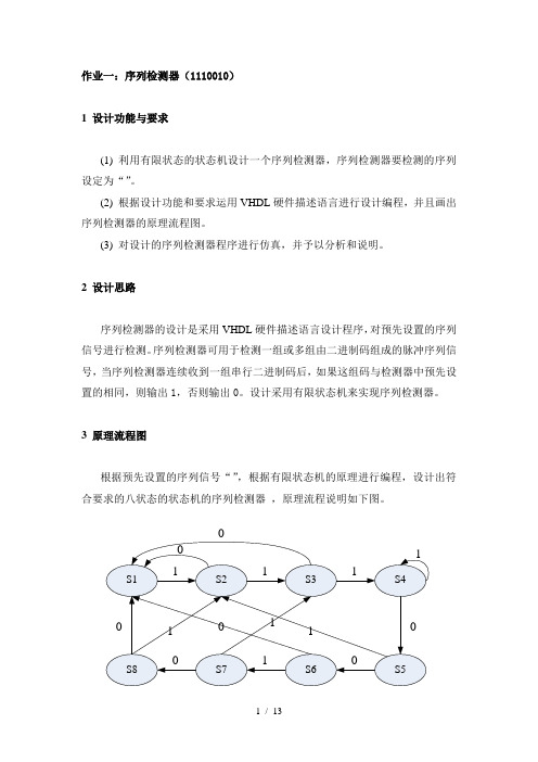
3 原理流程图根据预先设置的序列信号“”,根据有限状态机的原理进行编程,设计出符合要求的八状态的状态机的序列检测器,原理流程说明如下图。
如图所示,假设状态机的初始状态为S1,当输入信号为“1”时,进入S2状态;为“0”还是在S1状态。
在S2状态下,如果输入信号为“1”,则进入S3状态,为“0”则返回S1状态。
在S3状态下,如果输入信号为“1”,则进入S4状态,为“0”则返回S1状态。
在S4状态下,如果输入信号为“0”,则进入S5状态,为“0”还是在S4状态。
在S5状态下,如果输入信号为“0”,则进入S6状态,为“1”则进入S2状态。
在S6状态下,如果输入信号为“1”,则进入S7状态,为“0”则返回S1状态。
在S7状态下,如果输入信号为“0”,则进入S8状态,为“1”则进入S3状态。
在S8状态下,如果输入信号为“1”,则进入S2状态,为“0”则返回S1状态,并输出序列信号1110010。
4 序列检测器VHDL程序代码在序列检测器的程序代码中采用cin表示输入序列信号,clr为复位控制信号,clk为时钟信号,cout为输出信号。
当检测到序列信号中出现““序列的时候,cout输出为高电平,否则为低电平,详细程序代码如下。
library ieee;use ieee.std_logic_1164.all;entity sq_det isport(cin,clr,clk:in std_logic;cout:out std_logic);end sq_det;architecture behav of sq_det istype state is(s1,s2,s3,s4,s5,s6,s7,s8);signal c_state,n_state:state;beginprocess(clk,clr)beginif(clr='1')thenc_state<=s1;elsif(clk'event and clk='1')then c_state <=n_state;end if;end process;process(c_state,cin)begincase(c_state) iswhen s1=>cout<='0';if(cin='1')thenn_state<=s2;elsen_state<=s1;end if;when s2=>cout<='0';if(cin='1')thenn_state<=s3;elsen_state<=s1;end if;when s3=>cout<='0';if(cin='1')thenn_state<=s4;elsen_state<=s1;end if;when s4=>cout<='0';if(cin='1')thenn_state<=s4;elsen_state<=s5;end if;when s5=>cout<='0';if(cin='1')thenn_state<=s2;elsen_state<=s6;end if;when s6=>cout<='0';if(cin='1')thenn_state<=s7;elsen_state<=s1;end if;when s7=>cout<='0';if(cin='1')thenn_state<=s3;elsen_state<=s8;end if;when s8=>cout<='1';if(cin='1')thenn_state<=s2;elsen_state<=s1;end if;end case;end process;end architecture behav;5 仿真结果与说明序列检测器程序仿真结果如下图,cin为输入序列信号,clr为复位控制信号,高电平复位清零准备进入工作状态,clk为时钟信号,cout为输出信号。
Verilog--序列检测器(采用移位寄存器实现)

Verilog--序列检测器(采⽤移位寄存器实现)Verilog --序列检测器(采⽤移位寄存器实现)序列检测器就是将⼀个指定序列从数字码流中识别出来。
本例中将设计⼀个“10010”序列的检测器。
设X为数字码流的输⼊,Z为检测出标记输出,⾼电平表⽰发现指定的序列10010.考虑码流为110010010000100101这篇博客,才发现原来使⽤移位寄存器可以如此简单,原理图如下:基本思路就是利⽤移位寄存器作为检测窗⼝,每进来⼀个数就跟⽬标序列进⾏⽐较,简单粗暴。
下⾯贴⼀下原帖的代码:module seqdet(input wire x,input wire clk,input wire rst,output wire z,output reg [4:0] q);//reg [4:0] q;assign z = (q == 5'b10010) ? 1'b1:1'b0;always @ (posedge clk,negedge rst)if(!rst)q <= 5'd0;elseq <= {q[3:0],x};endmoduletestbench:`timescale 1ns/1nsmodule seqdet_tb;localparam T =20;reg clk,rst;reg [23:0] data;wire z,x;wire [4:0] q;assign x = data[23];initialbeginclk =0;rst =1;#2 rst =0;#30 rst =1;data =20'b1100_1001_0000_1001_0100;#(T*1000) $stop;endalways #T clk = ~clk;always @ (posedge clk)#2 data = {data[22:0],data[23]};seqdet U1(.x(x),.z(z),.clk(clk),.q(q),.rst(rst));endmodule由于移位寄存器的赋值是在always块中,故⽽相对实际延迟了⼀个clk.由上⾯的⽅针结果可知,输出z相对x晚了⼀个时钟周期,因为由于移位寄存器的赋值是在always块中,故⽽相对实际延迟了⼀个clk.Note:跟⽤状态机实现的区别在于,使⽤移位寄存器需要存储所有的码字,因此如果序列长度为N,则该⽅法需要消耗的寄存器就是N个。
VHDL作业

VDHL数字系统设计与测试作业1:7位序列码检测器作业2: 3位任意序列检测器目录作业一:7位序列码检测器 (2)1. 设计要求 (2)2. 设计思路 (3)3. 原理图 (3)4. 源代码 (3)5. 仿真结果与说明 (9)作业二:3位任意序列码检测器 (11)1.设计要求 (11)2.设计思路 (11)3.原理图 (11)4.源代码 (11)5.仿真结果说明 (11)作业总结: (16)作业一:7位序列码检测器1.设计要求7位特定序列检测器是在输入的二值序列中检测出特定的序列,例如特定序列为“1110010”,在输入为“0101011100101101…”时,我们在第12个数输入时,检测到特定序列,从而输出1。
2.设计思路由于输入信号是连续的单比特信号,而需要检测的序列有7比特,因此有必要在电路中引入记忆元件,记录当前检测到的序列状态。
记忆元件的数据宽度为7比特,因此共有128种取值。
若将128种取值分别看做一个状态,这样也可以实现检测功能,但状态机的状态数就需要128个。
实际中,进行状态化简后,可简化为8个状态。
3.原理图8个状态及转移图如下:4.源代码树状图:测试程序代码:--------------------------------------------------------------------- -- Company:-- Engineer:---- Create Date: 20:37:30 04/26/2014-- Design Name:-- Module Name: F:/ISE/hbs_detect/test.vhd-- Project Name: hbs_detect-- Target Device:-- Tool versions:-- Description:---- VHDL Test Bench Created by ISE for module: hbs_detect---- Dependencies:---- Revision:-- Revision 0.01 - File Created-- Additional Comments:---- Notes:-- This testbench has been automatically generated using types std_logic and-- std_logic_vector for the ports of the unit under test. Xilinx recommends-- that these types always be used for the top-level I/O of a design in order-- to guarantee that the testbench will bind correctly to the post-implementation-- simulation model.--------------------------------------------------------------------------------LIBRARY ieee;USE ieee.std_logic_1164.ALL;-- Uncomment the following library declaration if using-- arithmetic functions with Signed or Unsigned values--USE ieee.numeric_std.ALL;ENTITY test ISEND test;ARCHITECTURE behavior OF test IS-- Component Declaration for the Unit Under Test (UUT)COMPONENT hbs_detectPORT(clk : IN std_logic;reset : IN std_logic;sin : IN std_logic;result : OUT std_logic);END COMPONENT;--Inputssignal clk : std_logic := '0';signal reset : std_logic := '0';signal sin : std_logic := '0';--Outputssignal result : std_logic;-- Clock period definitionsconstant clk_period : time := 10 ns; BEGIN-- Instantiate the Unit Under Test (UUT) uut: hbs_detect PORT MAP (clk => clk,reset => reset,sin => sin,result => result);-- Clock process definitionsclk_process :processbeginclk <= '0';wait for clk_period/2;clk <= '1';wait for clk_period/2;end process;-- Stimulus processstim_proc: processbegin-- hold reset state for 20 ns.wait for 20 ns;sin<='0';wait for clk_period;sin<='1';wait for clk_period;sin<='0';wait for clk_period;sin<='1';wait for clk_period;sin<='0';wait for clk_period;sin<='1';wait for clk_period;sin<='1';wait for clk_period;sin<='1';wait for clk_period;sin<='0';wait for clk_period;sin<='0';wait for clk_period;sin<='1';wait for clk_period;sin<='0';wait for clk_period;sin<='1';wait for clk_period;sin<='1';wait for clk_period;sin<='0';wait for clk_period;sin<='1';wait for 5*clk_period;-- insert stimulus hereend process;END;主代码:------------------------------------------------------------------------------------ Company:-- Engineer:---- Create Date: 20:35:58 04/26/2014-- Design Name:-- Module Name: hbs_detect - Behavioral-- Project Name:-- Target Devices:-- Tool versions:-- Description:---- Dependencies:---- Revision:-- Revision 0.01 - File Created-- Additional Comments:------------------------------------------------------------------------------------library IEEE;use IEEE.STD_LOGIC_1164.ALL;-- Uncomment the following library declaration if using-- arithmetic functions with Signed or Unsigned values--use IEEE.NUMERIC_STD.ALL;-- Uncomment the following library declaration if instantiating -- any Xilinx primitives in this code.--library UNISIM;--use UNISIM.VComponents.all;entity hbs_detect isport(clk:in STD_LOGIC;reset:in STD_LOGIC;sin:in STD_LOGIC;result:out STD_LOGIC);end hbs_detect;architecture Behavioral of hbs_detect istype iState is(s1,s2,s3,s4,s5,s6,s7,s8);signal state_current,state_next:iState;begin--状态更新过程process(clk)beginif(rising_edge(clk))thenif(reset='1')thenstate_current<=s1;elsestate_current<=state_next;end if;end if;end process;--下一状态产生和输出信号产生process(state_current,sin)begincase(state_current)isWhen s1=>result<='0';if(sin='0')thenstate_next<=s1;elsestate_next<=s2;end if;When s2=>result<='0';if(sin='0')thenstate_next<=s1;elsestate_next<=s3;end if;When s3=>result<='0';if(sin='0')thenstate_next<=s1;elsestate_next<=s4;end if;When s4=>result<='0';if(sin='0')thenstate_next<=s5;elsestate_next<=s4;end if;When s5=>result<='0';if(sin='0')thenstate_next<=s6;elsestate_next<=s2;end if;When s6=>result<='0';if(sin='0')thenstate_next<=s1;elsestate_next<=s7;end if;When s7=>result<='0';if(sin='0')thenstate_next<=s8;elsestate_next<=s3;end if;When s8=>result<='1';if(sin='0')thenstate_next<=s1;elsestate_next<=s2;end if;When others=>null;end case;end process;end Behavioral;5.仿真结果与说明由激励信号和上图可以看出,在输入“0101011100101101…”时,状态转移为s1,s2, s1,s2,s1,s2,s3,s4,s5,s6,s7,s8,s2,s3,且,在状态s8时,检测到序列,输出信号为高电平。
Verilog-数字序列检测器101(米利型)
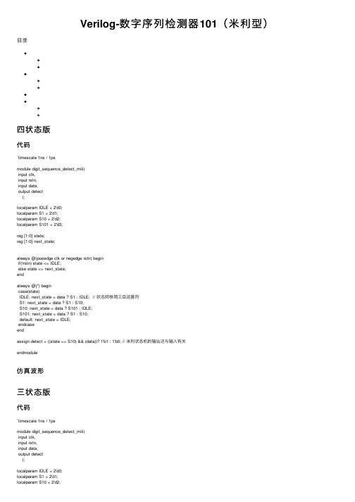
Verilog-数字序列检测器101(⽶利型)⽬录四状态版代码`timescale 1ns / 1psmodule digit_sequence_detect_mili(input clk,input rstn,input data,output detect);localparam IDLE = 2'd0;localparam S1 = 2'd1;localparam S10 = 2'd2;localparam S101 = 2'd3;reg [1:0] state;reg [1:0] next_state;always @(posedge clk or negedge rstn) beginif(!rstn) state <= IDLE;else state <= next_state;endalways @(*) begincase(state)IDLE: next_state = data ? S1 : IDLE; // 状态转移⽤三⽬运算符S1: next_state = data ? S1 : S10;S10: next_state = data ? S101 : IDLE;S101: next_state = data ? S1 : S10;default: next_state = IDLE;endcaseendassign detect = ((state == S10) && (data))? 1'b1 : 1'b0; // ⽶利状态机的输出还与输⼊有关endmodule仿真波形三状态版代码`timescale 1ns / 1psmodule digit_sequence_detect_mili(input clk,input rstn,input data,output detect);localparam IDLE = 2'd0;localparam S1 = 2'd1;localparam S10 = 2'd2;localparam S101 = 2'd3;reg [1:0] state;reg [1:0] next_state;always @(posedge clk or negedge rstn) beginif(!rstn) state <= IDLE;else state <= next_state;endalways @(*) begincase(state)IDLE: next_state = data ? S1 : IDLE;S1: next_state = data ? S1 : S10;S10: next_state = data ? S1 : IDLE; // 在S10状态下,输⼊1直接跳回S1状态,从⽽可以节省⼀个状态//S101: next_state = data ? S1 : S10;default: next_state = IDLE;endcaseendassign detect = ((state == S10) && (data))? 1'b1 : 1'b0;endmodule仿真波形总结可以看到,三状态版的仿真波形与四状态版的仿真波形⼀致,对于⽶利型序列检测器,最少状态数为序列长度,对于摩尔型序列检测器,最少状态数为序列长度加1.⽶利型序列检测器在当周期出检测结果,摩尔型序列检测器在下⼀周期出检测结果移位寄存器版本,并且是⽶利型的效果,还不带重叠检测代码reg [2:0] shifter;always @(posedge clk or negedge rstn) beginif(!rstn) shifter <= 0;else if(detect) beginshifter <= 0;endelse beginshifter <= {shifter[1:0],data};endendassign detect = (shifter[1:0] == 2'b10 && data == 1'b1); // 已经检测到10,下个数据如果是1就置⾼检测标志仿真波形。
VHDL程序练习题(含答案)

VHDL程序填空题(一)在下面横线上填上合适的VHDL关键词,完成2选1多路选择器的设计。
LIBRARY IEEE;USE IEEE。
STD_LOGIC_1164.ALL;1 MUX21 ISPORT(SEL:IN STD_LOGIC;A,B:IN STD_LOGIC;Q:OUT STD_LOGIC );END MUX21;2 BHV OF MUX21 ISBEGINQ<=A WHEN SEL=’1’ ELSE B;END BHV;(二)在下面横线上填上合适的语句,完成BCD—7段LED显示译码器的设计。
LIBRARY IEEE ;USE IEEE.STD_LOGIC_1164。
ALL;ENTITY BCD_7SEG ISPORT(BCD_LED :IN STD_LOGIC_VECTOR(3 DOWNTO 0);LEDSEG :OUT STD_LOGIC_VECTOR(6 DOWNTO 0));END BCD_7SEG;ARCHITECTURE BEHA VIOR OF BCD_7SEG ISBEGINPROCESS(BCD_LED)3IF BCD_LED="0000” THEN LEDSEG<=”0111111”;ELSIF BCD_LED=”0001” THEN LEDSEG<="0000110”;ELSIF BCD_LED=”0010" THEN LEDSEG<= 4 ;ELSIF BCD_LED=”0011" THEN LEDSEG<=”1001111";ELSIF BCD_LED=”0100" THEN LEDSEG<="1100110";ELSIF BCD_LED=”0101" THEN LEDSEG〈="1101101";ELSIF BCD_LED=”0110" THEN LEDSEG〈=”1111101";ELSIF BCD_LED=”0111" THEN LEDSEG〈="0000111";ELSIF BCD_LED="1000" THEN LEDSEG〈=”1111111”;ELSIF BCD_LED="1001” THEN LEDSEG<="1101111”;ELSE LEDSEG<= 5 ;END IF;END PROCESS;END BEHA VIOR;(三) 在下面横线上填上合适的语句,完成数据选择器的设计。
VHDL第一次作业报告

一、题目及要求:用状态机实现101110序列检测器。
二、题目解析:1、根据数字电子线路知识,序列检测器就是根据输入端输入的值判断出目前序列与所给序列是否相同,如果不相同,输出为0,继续判断出下一状态,如果相同,则输出1;2、本题目的难点和易错点就是对于在判断出目前序列为所给序列时,根据当前输入判断下一状态,这是易错点也是难点。
如当目前序列位101110时,输出结果为1,当输入位1时应该为状态101,而不是回到初始状态,此情况对于某些中间状态也是类似的。
3、另外代码设计过程需要注意的就是case语句一定有others情况状态转移及状态输出。
三、设计思路:本题目设计使用的是目前常用的三段式状态机:状态更新(时序逻辑)、状态转移(组合逻辑)、状态输出(时序逻辑),采用本方法的优点是实现起来结构简单,逻辑清楚。
状态更新部分clk_process:该段主要就是在每次时钟上升沿时更新下一状态,具体实现语句为:current_state <= next_state;状态转移部分Comb_process:该段主要是根据当前所处状态和信号输入值判断出下一状态,为纯组合逻辑;状态输出output_process:判断目前状态与所给序列是否相同,如果相同,则输出为1.否则为0。
四、原理图说明:所检测序列为6位的101110,因此应有7种状态:S0、S1、S2、S3、S4、S5、S6,它们分别代表当前状态为:S0:0 S1:1 S2:10 S3:101 S4:1011 S5:10111 S6:101110.下图为具体的状态转移图:图1状态转移图五、程序源代码:主程序代码:-----------------------------------------------------------------------library IEEE;use IEEE.STD_LOGIC_1164.ALL;entity seq_test isport ( clk : in STD_LOGIC;rst : in STD_LOGIC;seq_in : in STD_LOGIC;test_result : out STD_LOGIC);end seq_test;architecture Behavioral of seq_test istype MY_STATE is (S0,S1,S2,S3,S4,S5,s6,s7);signal current_state,next_state:MY_STATE;begin--以下为第一段状态更新程序clk_process:process(clk,rst)beginif(rst = '0')thencurrent_state <= S0;elsif rising_edge(clk) thencurrent_state <= next_state;end if;end process clk_process;--以下为第二段状态转移程序Comb_process:process(current_state,seq_in)begin case(current_state)iswhen S0 =>if(seq_in = '1')thennext_state <= S1;elsenext_state <= S0;end if;when S1 =>if(seq_in = '0')thennext_state <= S2;elsenext_state <= S1;end if;when S2 =>if(seq_in = '1')thennext_state <= S3;elsenext_state <= S0;end if;when S3 =>if(seq_in = '1')thennext_state <= S4;elsenext_state <= S1;end if;when S4 =>if(seq_in = '1')thennext_state <= S5;elsenext_state <= S2;end if;when S5 =>if(seq_in = '0')thennext_state <= S6;elsenext_state <= S1;end if;when S6 =>if(seq_in = '1')thennext_state <= S3;elsenext_state <= S0;end if;when others =>next_state <= next_state;end case;end process Comb_process;--以下为第三段状态输出程序Output_process:process(clk,rst)begin if(rst = '0')thentest_result <= '0';elsif rising_edge (clk)thencase(next_state)iswhen S0 =>test_result <= '0';when S1 =>test_result <= '0';when S2 =>test_result <= '0';when S3 =>test_result <= '0';when S4 =>test_result <= '0';when S5 =>test_result <= '0'; when S6 =>test_result <= '1';when others =>test_result <= '0';end case;end if;end process Output_process;end Behavioral;测试程序代码(输入序列为:010111011100101):----------------------------------------------------------------------- LIBRARY ieee;USE ieee.std_logic_1164.ALL;ENTITY tb_seq_test ISEND tb_seq_test;ARCHITECTURE behavior OF tb_seq_test ISCOMPONENT seq_testPORT(clk : IN std_logic;rst : IN std_logic;seq_in : IN std_logic;test_result : OUT std_logic);END COMPONENT;signal clk : std_logic := '0';signal rst : std_logic := '0';signal seq_in : std_logic := '0';signal test_result : std_logic;constant clk_period : time := 10 ns;BEGIN-- Instantiate the Unit Under Test (UUT)uut: seq_test PORT MAP (clk => clk,rst => rst,seq_in => seq_in,test_result => test_result);-- Clock process definitionsclk_process :processbeginclk<= '0';wait for clk_period/2;clk<= '1';wait for clk_period/2;end process;-- Stimulus processstim_proc: processbeginrst<= '1' ;wait for 5 ns;rst<= '0' ;wait for 10 ns;rst<= '1' ;wait for clk_period;seq_in <= '0' ;wait for clk_period;seq_in <= '1' ;wait for clk_period;seq_in <= '0' ;wait for clk_period;seq_in <= '1' ;wait for clk_period;seq_in <= '1' ;wait for clk_period;seq_in <= '1' ;wait for clk_period;seq_in <= '0' ;wait for clk_period;seq_in <= '1' ;wait for clk_period;seq_in <= '1' ;wait for clk_period;seq_in <= '1' ;wait for clk_period;seq_in <= '0' ;wait for clk_period;seq_in <= '0' ;wait for clk_period;seq_in <= '1' ;wait for clk_period;seq_in <= '0' ;wait for clk_period;seq_in <= '1' ;wait;end process;END;六、仿真结果:图2仿真结果由于输入序列为010111011100101,满足条件的序列一共有2个,因此正确输出test_result应该有高电平,如图2所示。
VHDL5套试卷标准答案
填空题:1、一般将一个完整的VHDL程序称为设计实体2、VHDL设计实体的基本结构由(库)、(程序包)、(实体)、(结构体)和(配置)组成。
3、(实体)和(结构体)是设计实体的基本组成部分,它们可以构成最基本的VHDL 程序。
4、根据VHDL语法规则,在VHDL程序中使用的文字、数据对象、数据类型都需要(事先声明)。
5、在VHDL中最常用的库是(IEEE)标准库,最常用的数据包是(STD_LOGIC_1164)数据包。
6、VHDL的实体由(实体声明)部分和(结构体)组成。
7、VHDL的实体声明部分指定了设计单元的(输入出端口)或(引脚),它是设计实体对外的一个通信界面,是外界可以看到的部分。
8、VHDL的结构体用来描述实体的(逻辑结构)和(逻辑功能),它由VHDL 语句构成,是外界看不到的部分。
9、在VHDL的端口声明语句中,端口方向包括(输入)、(输出)、(双向)和(缓冲)。
10、VHDL的标识符名必须以(字母开头),后跟若干字母、数字或单个下划线构成,但最后不能为(下划线)11、VHDL的数据对象包括(常量)、(变量)和(信号),它们是用来存放各种类型数据的容器。
12、为信号赋初值的符号是(:=);程序中,为变量赋值的符号是(:=),为信号赋值的符号是(<=)13、VHDL的数据类型包括(标量类型)、(复合类型)、(存储类型)和(文件类型)。
14、在VHDL中,标准逻辑位数据有(九)种逻辑值。
15、VHDL的操作符包括(逻辑)、(算术)、(关系)和(并置)四类。
选择题:1、IEEE于1987年公布了VHDL的(A)语法标准。
A、IEEE STD 1076-1987;B、RS232;C、IEEE STD_LOGIC_1164;D、IEEE STD 1076-1993;2、IEEE于1987年公布了VHDL的(D)语法标准。
A、IEEE STD 1076-1987;B、RS232;C、IEEE STD_LOGIC_1164;D、IEEE STD 1076-1993;3、VHDL的设计实体可以被高层次的系统(D ),成为系统的一部分。
- 1、下载文档前请自行甄别文档内容的完整性,平台不提供额外的编辑、内容补充、找答案等附加服务。
- 2、"仅部分预览"的文档,不可在线预览部分如存在完整性等问题,可反馈申请退款(可完整预览的文档不适用该条件!)。
- 3、如文档侵犯您的权益,请联系客服反馈,我们会尽快为您处理(人工客服工作时间:9:00-18:30)。
3比特的任意二值序列检测器(101)
1,设计功能与要求:
用状态机设计序列检测器(101)。
设计一个序列检测器,检测的序列流为“101”,当输入信号依次为“101”时输出一个高电平,否则输出为低电平。
2,设计思路:
序列检测器是一种同步时序电路,它用于搜索,检测输入的二进制代码串中是否出现指定的代码序列,101序列检测器的原理图如下:
CP
X Z 01010
10
01
1
0001
3,状态转移图:
本检测器要从一串二进制编码中检测出三位二进制码101,每增加一位相当于增加一个状态,再加上一个初始态,用四个状态可以实现,其Moore型原始状态转移图已给出,如下图:
根据状态转移图可以得出Moore型原始状态转移表为:
4,源代码:
library ieee;
use ieee.std_logic_1164.all;
entity check is
port(x:in std_logic;
clk,rst:in std_logic;
z:out std_logic);
end check;
architecture arch_check of check is
type statetype is(s1,s2,s3,s4);
signal present_state,next_state:statetype;
begin
state_comb:process(present_state,x)
begin
case present_state is
when s1=>z<='0';
if x='1'then
next_state<=s2;
else
next_state<=s1;
end if;
when s2=>z<='0';
if x='1'then
next_state<=s2;
else
next_state<=s3;
end if;
when s3=>z<='0';
if x='1'then
next_state<=s4;
else
next_state<=s1;
end if;
when s4=>z<='1';
if x='1'then
next_state<=s2;
else
next_state<=s3;
end if;
end case;
end process state_comb;
state_clocked:process(clk,rst)
begin
if(rst='1')then
present_state<=s1;
elsif(clk'event and clk='1')then
present_state<=next_state;
end if;
end process state_clocked;
end arch_check;
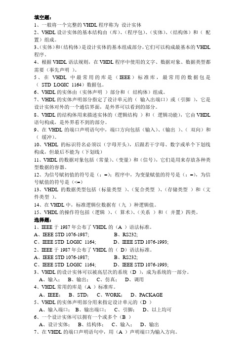
5,仿真结果:
6,仿真结果分析:
如上图所示,当输入第一个101序列时,由于复位信号输出信号Z一直输出低电平,当输入第二个101序列时,在收到最后一个1并在时钟上升沿时z输出一个高电平。
符合设计要求。