共立203中文使用说明书
ID203中文技术手册_充绒机专用版本_R1.0_20150505

ID203WEIGHING TRANSFER称重变送器OPERATION MANUAL操作说明书充绒机专用版本2015/05Rev0.2目录1概述 (3)2键盘菜单 (4)2.1键盘操作说明 (4)2.2菜单说明 (4)2.2.1 [1 ]1#通道秤台 (4)2.2.2 [2 ]2#通道秤台 (6)2.2.3 [3 ]3#通道秤台 (7)2.2.6[6 ]通讯接口功能块 (9)2.2.7[11 ]维护功能块 (9)3串口通讯 (10)3.1MODBUS-RTU1 (10)3.2MODBUS-RTU2 (12)3.33秤模式连续输出 (14)3.3连续输出3路ADC内码格式 (16)版本记录版本更改内容时间V0.1 第一版本2015/051概述ID203是一种标准工业导轨(DIN)安装的过程称重控制显示仪表,主要应用与工业过程称重、和配料系统,通过RS232/485串口通讯,PLC或DCS系统很容易得到3路传感器的AD码或是3个秤台的重量性能指标z24VDC电源输入, 整机最大功耗小于3Wz3路传感器接口, 每路最多支持4个350欧姆模拟传感器输入z1路 RS232/485 串口z1路CAN 通讯口¾连续输出3通道的内码¾连续输出3个秤台的重量¾MODBUS-RTU 读取3路秤台的重量z200Hz A/D转换速度z标准工业导轨(DIN) 安装z温度和湿度¾使用温度为:-100C∼400C,湿度为10%∼95%,不冷凝。
¾存贮温度为:-400C∼600C,湿度为10%∼95%,不冷凝。
2 键盘菜单2.1键盘操作说明长按住,将进入菜单设定界面[1 ] 1#通道秤台 Æ [2 ] 2#通道秤台 Æ[3 ]3#通道秤台Æ [6 ] 串口通讯接口功能块 Æ[11 ] 维护功能块2.2 菜单说明2.2.1 [1 ]1#通道秤台[1.1 ] 分度值0 (0.001), 1 (0.002), 2 (0.005), 3 (0.01), 4 (0.02), 5 (0.05), 6 (0.1), 7 (0.2), 8 (0.5), 9 (1), 10 (2), 11 (5), 12 (10), 13 (20), 14 (50), 15 (100)[1.2 ] 容量[1.3 ]标定模式0- 2 点标定,只支持[1.4 ](零点校正) 和[1.6 ] (量程校正)1 – 免砝码标定[1.4 ]零点校正校正过程:[ CAL-0] [ 10] Æ [ 9] Æ…Æ[ 1] Æ[ 0] Æ[ SAVE?]10、9… 2、1: 校正过程中100 – 动态过程中校正失败0 – 校正成功–255[1.6 ] 量程校正校正过程:[ CAL-2] 输入校正重量 [ 3000] [ Ld-SP2] 加载砝码[ 10] Æ[ 9] Æ…Æ[ 1] Æ[ 0] Æ[ SAVE?]10、9… 2、1: 校正过程中100 – 动态过程中–校正失败0 – 校正成功255[1.7 ] 免砝码标定功能块[1.7.1 ] 传感器容量输入当前秤台单传感器的容量[1.7.2 ] 总传感器数输入当前秤台的总传感器数[1.7.3 ] 工作传感器数输入当前秤台的实际使用传感器数[1.7.4 ] 传感器灵敏度输入传感器灵敏度,主要要考虑衰减系数, 一般的传感器虽然标了2mV/V,但实际灵敏度不是2mV/V, 还有几个传感器通过接线盒,灵敏度又会带来衰减, 所以实际应用的时候,输入的灵敏度将直接影响到标定精度.免砝码标定举例:4 个100kg容量的传感器做成的秤, 每个传感器的灵敏度为2.0mV/V, 经过接线盒衰减为1.92mV/V; 下面是免标定过程:1) 设置[1.1 ]分度值, 根据需要设置2) 设置[1.2 ] 容量为4003)设置[1.3 ]标定模式为1(免砝码标定)标定零点见[1.4 ]4)5) [1.7.1 ] 传感器容量设置为 1006) [1.7.2 ] 总传感器数设置为 4[1.7.3 ] 工作传感器数设置为 47)8) [1.7.4 ] 传感器灵敏度设置为 1.92000mV/V[1.8 ] 滤波0(最轻) 1,2,3,4(最深)[1.9 ] 键盘清零范围0– 禁止键盘清零1,2,5,10 :分别为容量的1%,2%,5%,10% 范围内允许清零[1.10 ] 动态监测0– 禁止监测0.1~9.9 – 允许动态监测[1.A.1 ] : 查看零点校正内码[1.A.2 ] : 查看量程校正内码[1.A.3 ] : 查看量程校正重量[1.A.4 ] : 修改或输入零点校正内码[1.A.5 ] : 修改或输入量程校正内码[1.A.6 ] : 修改或输入量程校正重量2.2.2 [2 ]2#通道秤台[2.1 ]分度值0 (0.001), 1 (0.002), 2 (0.005), 3(0.01), 4(0.02), 5 (0.05),6 (0.1),7 (0.2),8 (0.5), 9(1), 10(2), 11 (5),12 (10), 13 (20), 14 (50), 15 (100)[2.2 ]容量[2.3 ]标定模式0- 2 点标定,只支持[2.4 ](零点校正) 和[2.6 ] (量程校正)1 – 免砝码标定[2.4 ]零点校正校正过程:[ CAL-0] [ 10] Æ [ 9] Æ…Æ[ 1] Æ[ 0] Æ[ SAVE?]10、9… 2、1: 校正过程中100 – 动态过程中–校正失败0 – 校正成功255[2.6 ] 量程校正校正过程:[ CAL-2] 输入校正重量 [ 3000] [ Ld-SP2] 加载砝码[ 10] Æ[ 9] Æ…Æ[ 1] Æ[ 0] Æ[ SAVE?]10、9… 2、1: 校正过程中100 – 动态过程中校正失败0 – 校正成功–255[2.7 ] 免砝码标定功能块[2.7.1 ] 传感器容量输入当前秤台单传感器的容量[2.7.2 ] 总传感器数输入当前秤台的总传感器数[2.7.3 ] 工作传感器数输入当前秤台的实际使用传感器数[2.7.4 ] 传感器灵敏度输入传感器灵敏度,主要要考虑衰减系数, 一般的传感器虽然标了2mV/V,但实际灵敏度不是2mV/V, 还有几个传感器通过接线盒,灵敏度又会带来衰减, 所以实际应用的时候,输入的灵敏度将直接影响到标定精度.免砝码标定举例:4 个100kg容量的传感器做成的秤, 每个传感器的灵敏度为2.0mV/V, 经过接线盒衰减为1.92mV/V; 下面是1) 设置[2.1 ]分度值, 根据需要设置2) 设置[2.2 ] 容量为4003)设置[2.3 ]标定模式为1(免砝码标定)标定零点见[2.4 ]4)5) [2.7.1 ] 传感器容量设置为 1006) [2.7.2 ] 总传感器数设置为 4[2.7.3 ] 工作传感器数设置为 47)8) [2.7.4 ] 传感器灵敏度设置为 1.92000mV/V[2.8 ] 滤波0(最轻) 1,2,3,4(最深)[2.9 ] 键盘清零范围0– 禁止键盘清零1,2,5,10 :分别为容量的1%,2%,5%,10% 范围内允许清零[2.10 ] 动态监测0– 禁止监测0.1~9.9 – 允许动态监测[2.A ][2.A.1 ] : 查看零点校正内码[2.A.2 ] : 查看量程校正内码[2.A.3 ] : 查看量程校正重量[2.A.4 ] : 修改或输入零点校正内码[2.A.5 ] : 修改或输入量程校正内码[2.A.6 ] : 修改或输入量程校正重量2.2.3 [3 ]3#通道秤台[3.1 ]分度值0 (0.001), 1 (0.002), 2 (0.005), 3(0.01), 4(0.02), 5 (0.05),6 (0.1),7 (0.2),8 (0.5), 9(1), 10(2), 11 (5),12 (10), 13 (20), 14 (50), 15 (100)[3.2 ]容量[3.3 ]标定模式0- 2 点标定,只支持[3.4 ](零点校正) 和[3.6 ] (量程校正)1 – 免砝码标定[3.4 ]零点校正校正过程:[ CAL-0] [ 10] Æ [ 9] Æ…Æ[ 1] Æ[ 0] Æ[ SAVE?]10、9… 2、1: 校正过程中100 – 动态过程中校正失败0 – 校正成功–255[3.6 ] 量程校正校正过程:[ CAL-2] 输入校正重量 [ 3000] [ Ld-SP2] 加载砝码[ 10] Æ[ 9] Æ…Æ[ 1] Æ[ 0] Æ[ SAVE?]10、9… 2、1: 校正过程中100 – 动态过程中255校正失败0 – 校正成功–[3.7 ] 免砝码标定功能块[3.7.1 ] 传感器容量输入当前秤台单传感器的容量[3.7.2 ] 总传感器数输入当前秤台的总传感器数[3.7.3 ] 工作传感器数输入当前秤台的实际使用传感器数[3.7.4 ] 传感器灵敏度输入传感器灵敏度,主要要考虑衰减系数, 一般的传感器虽然标了2mV/V,但实际灵敏度不是2mV/V, 还有几个传感器通过接线盒,灵敏度又会带来衰减, 所以实际应用的时候,输入的灵敏度将直接影响到标定精度.免砝码标定举例:4 个100kg容量的传感器做成的秤, 每个传感器的灵敏度为2.0mV/V, 经过接线盒衰减为1.92mV/V; 下面是免标定过程:1) 设置[3.1 ]分度值, 根据需要设置2) 设置[3.2 ] 容量为4003)设置[3.3 ]标定模式为1(免砝码标定)4) 标定零点见[3.4 ]5) [3.7.1 ] 传感器容量设置为 1006) [3.7.2 ] 总传感器数设置为 4[3.7.3 ] 工作传感器数设置为 47)8) [3.7.4 ] 传感器灵敏度设置为 1.92000mV/V[3.8 ] 滤波0(最轻) 1,2,3,4(最深)[3.9 ] 键盘清零范围0– 禁止键盘清零1,2,5,10 :分别为容量的1%,2%,5%,10% 范围内允许清零[3.10 ] 动态监测0– 禁止监测0.1~9.9 – 允许动态监测[3.A ][3.A.1 ] : 查看零点校正内码[3.A.2 ] : 查看量程校正内码[3.A.3 ] : 查看量程校正重量[3.A.4 ] : 修改或输入零点校正内码[3.A.5 ] : 修改或输入量程校正内码[3.A.6 ] : 修改或输入量程校正重量2.2.6[6 ]通讯接口功能块[6.1 ] 节点地址输入范围为1 ~ 99,用于串口MODBUS-RTUMODBUS-RTU支持1 ~ 99[6.2 ]串口工作波特率0 – 波特率为1200,8,1,N 1 -波特率为2400,8,1,N2 -波特率为4800,8,1,N3 -波特率为9600,8,1,N4 -波特率为19200,8,1,N5 -波特率为38400,8,1,N6 -波特率为57600,8,1,N[6.3 ]串口工作模式rtU1 – MODBUS-RTU 3秤模式下读取重量Cnt1 – 3秤模式下连续输出3个秤台的重量Cnt2 – 连续输出3个通道的AD码rtU2 – MODBUS-RTU 3秤模式下读取重量2.2.7[11 ]维护功能块[11.1 ]第一通道ADC 内码[11.2 ]第二通道ADC 内码[11.3 ]第三通道ADC 内码3 串口通讯3.1 MODBUS-RTU1MODBUS-RTU1 3秤模式地址 说明 操作属性40001/2 1# 显示重量32位浮点数R 40003 1# 秤状态Bit 0 ~ Bit 7: 标定状态Bit 8 – 零中心Bit 9 – 下超载Bit 10 – 上超载Bit 11 – 净重Bit 12 – 动态B13 – 保留Bit 14 – 系统错误Bit 15– 数据有效R40004 1# 秤处理命令Bit0 – 0: 禁止远程标定 , 1-允许远程标定Bit 11 –0->1 触发键盘清零 (Zero)Bit 12 –0->1 触发键盘去皮 (Tare)Bit 13 –0->1 触发键盘清皮 (Clear)Bit15 – 0Æ1触发重新初始化, 在设置标定参数等后需要重新初始化R/W40005/6 2# 显示重量32位浮点数R 40007 2# 秤状态Bit 0 ~ Bit 7: 标定状态Bit 8 – 零中心Bit 9 – 下超载Bit 10 – 上超载Bit 11 – 净重Bit 12 – 动态B13 – 保留Bit 14 – 系统错误Bit 15– 数据有效R40008 2# 秤处理命令Bit0 – 0: 禁止远程标定 , 1-允许远程标定Bit 11 –0->1 触发键盘清零 (Zero)Bit 12 –0->1 触发键盘去皮 (Tare)Bit 13 –0->1 触发键盘清皮 (Clear)Bit15 – 0Æ1触发重新初始化, 在设置标定参数等后需要重新初始化R/W40009/10 3# 显示重量32位浮点数R/W 40011 3# 秤状态Bit 0 ~ Bit 7: 标定状态Bit 8 – 零中心Bit 9 – 下超载Bit 10 – 上超载Bit 11 – 净重Bit 12 – 动态B13 – 保留Bit 14 – 系统错误Bit 15– 数据有效R40012 3# 秤处理命令Bit0 – 0: 禁止远程标定 , 1-允许远程标定Bit 11 –0->1 触发键盘清零 (Zero)Bit 12 –0->1 触发键盘去皮 (Tare)Bit 13 –0->1 触发键盘清皮 (Clear)Bit15 – 0Æ1触发重新初始化, 在设置标定参数等后需要重新初始化R下页继续MODBUS-RTU1 3秤模式地址 说明 操作属性40013 1# 秤最大称量R/W 40014 1# 分度值索引R/W0 (0.001), 1 (0.002), 2 (0.005), 3 (0.01), 4 (0.02), 5 (0.05),6(0.1), 7(0.2), 8(0.5), 9(1), 10(2), 11(5), 12(10),13(20), 14(50), 15(100)40015 1# 秤标定砝码重量R/WR/W 40016 1# 键盘清零范围索引0 – 禁止键盘清零1 - ±1%2 - ±2%, 3 - ±10%40017 2# 秤最大称量R/W 40018 2# 分度值索引R/W0 (0.001), 1 (0.002), 2 (0.005), 3 (0.01), 4 (0.02), 5 (0.05),6(0.1), 7(0.2), 8(0.5), 9(1), 10(2), 11(5), 12(10),13(20), 14(50), 15(100)40019 2# 秤标定砝码重量R/W 40020 2# 键盘清零范围索引R/W0 – 禁止键盘清零1 - ±1%2 - ±2%, 3 - ±10%40021 3# 秤最大称量R/W 40022 3# 分度值索引R/W0 (0.001), 1 (0.002), 2 (0.005), 3 (0.01), 4 (0.02), 5 (0.05),6(0.1), 7(0.2), 8(0.5), 9(1), 10(2), 11(5), 12(10),13(20), 14(50), 15(100)40023 3# 秤标定砝码重量R/WR/W 40024 3# 键盘清零范围索引0 – 禁止键盘清零1 - ±1%2 - ±2%, 3 - ±10%40025 标定命令:R/W 0Æ1 1#秤零点标定0Æ3 1#秤量程标定0Æ11 2#秤零点标定0Æ13 2#秤量程标定0Æ21 3#秤零点标定0Æ23 3#秤量程标定40026 1# 标定模式0 – 2点标定 1-免砝码标定R/W 40027 1#免砝码标定:单传感器容量R/W 40028 1#免砝码标定:传感器数量R/W 40029 1#免砝码标定:实际用传感器数量R/W 40030 1#免砝码标定:传感器灵敏度:xxxxxÆ x.xxxx R/W 40031 2# 标定模式0 – 2点标定 1-免砝码标定R/W 40032 2#免砝码标定:单传感器容量R/W 40033 2#免砝码标定:传感器数量R/W 40034 2#免砝码标定:实际用传感器数量R/W 40035 2#免砝码标定:传感器灵敏度:xxxxxÆ x.xxxx R/W 40036 3# 标定模式0 – 2点标定 1-免砝码标定R/W 40037 3#免砝码标定:单传感器容量R/W 40038 3#免砝码标定:传感器数量R/W 40039 3#免砝码标定:实际用传感器数量R/W 40040 3#免砝码标定:传感器灵敏度:xxxxxÆ x.xxxx R/W 40041 1# ADC内码R 40042 2# ADC内码R 40043 3# ADC内码R3.2 MODBUS-RTU2MODBUS-RTU2 3秤模式地址 说明 操作属性40001/2 1# 显示重量32位浮点数R 40003/4 2# 显示重量32位浮点数R 40005/6 3# 显示重量32位浮点数R 40007/8 4# 显示重量32位浮点数R40009 1# 秤状态Bit 0 ~ Bit 7: 标定状态Bit 8 – 零中心Bit 9 – 下超载Bit 10 – 上超载Bit 11 – 净重Bit 12 – 动态B13– 保留Bit 14 – 系统错误Bit 15– 数据有效R40010 2# 秤状态Bit 0 ~ Bit 7: 标定状态Bit 8 – 零中心Bit 9 – 下超载Bit 10 – 上超载Bit 11 – 净重Bit 12 – 动态B13– 保留Bit 14 – 系统错误Bit 15– 数据有效40011 3# 秤状态Bit 0 ~ Bit 7: 标定状态Bit 8 – 零中心Bit 9 – 下超载Bit 10 – 上超载Bit 11 – 净重Bit 12 – 动态B13– 保留Bit 14 – 系统错误Bit 15– 数据有效40012 4# 秤状态Bit 0 ~ Bit 7: 标定状态Bit 8 – 零中心Bit 9 – 下超载Bit 10 – 上超载Bit 11 – 净重Bit 12 – 动态B13– 保留Bit 14 – 系统错误Bit 15– 数据有效40013 1# 秤处理命令Bit0 – 0: 禁止远程标定 , 1-允许远程标定Bit 11 –写1 触发键盘清零 (Zero),内部自动清除Bit 12 –写1触发键盘去皮 (Tare) ,内部自动清除Bit 13 –写1触发键盘清皮 (Clear) ,内部自动清除Bit15 – 0Æ1触发重新初始化, 在设置标定参数等后需要重新初始化R/W40014 2# 秤处理命令Bit0 – 0: 禁止远程标定 , 1-允许远程标定Bit 11 –写1 触发键盘清零 (Zero),内部自动清除Bit 12 –写1触发键盘去皮 (Tare) ,内部自动清除Bit 13 –写1触发键盘清皮 (Clear) ,内部自动清除Bit15 – 0Æ1触发重新初始化, 在设置标定参数等后需要重新初始化R/W40015 3# 秤处理命令Bit0 – 0: 禁止远程标定 , 1-允许远程标定Bit 11 –写1 触发键盘清零 (Zero),内部自动清除Bit 12 –写1触发键盘去皮 (Tare) ,内部自动清除Bit 13 –写1触发键盘清皮 (Clear) ,内部自动清除Bit15 – 0Æ1触发重新初始化, 在设置标定参数等后需要重新初始化R/W下页继续MODBUS-RTU2 3秤模式地址 说明 操作属性40016 4# 秤处理命令Bit0 – 0: 禁止远程标定 , 1-允许远程标定Bit 11 –写1 触发键盘清零 (Zero),内部自动清除Bit 12 –写1触发键盘去皮 (Tare) ,内部自动清除Bit 13 –写1触发键盘清皮 (Clear) ,内部自动清除Bit15 – 0Æ1触发重新初始化, 在设置标定参数等后需要重新初始化R/W40017 标定命令:0Æ1 1#秤零点标定0Æ3 1#秤量程标定0Æ11 2#秤零点标定0Æ13 2#秤量程标定0Æ21 3#秤零点标定0Æ23 3#秤量程标定R/W40018 1# 秤最大称量R/W 40019 2# 秤最大称量R/W 40020 3# 秤最大称量R/W 40021 4# 秤最大称量R/W 40022 1# 分度值索引0 (0.001), 1 (0.002), 2 (0.005), 3 (0.01), 4 (0.02), 5 (0.05),6(0.1), 7(0.2), 8(0.5), 9(1), 10(2), 11(5), 12(10),13(20), 14(50), 15(100)R/W40023 2# 分度值索引0 (0.001), 1 (0.002), 2 (0.005), 3 (0.01), 4 (0.02), 5 (0.05),6(0.1), 7(0.2), 8(0.5), 9(1), 10(2), 11(5), 12(10),13(20), 14(50), 15(100)R/W40024 3# 分度值索引0 (0.001), 1 (0.002), 2 (0.005), 3 (0.01), 4 (0.02), 5 (0.05),6(0.1), 7(0.2), 8(0.5), 9(1), 10(2), 11(5), 12(10),13(20), 14(50), 15(100)R/W40025 4# 分度值索引0 (0.001), 1 (0.002), 2 (0.005), 3 (0.01), 4 (0.02), 5 (0.05),6(0.1), 7(0.2), 8(0.5), 9(1), 10(2), 11(5), 12(10),13(20), 14(50), 15(100)R/W40026 1# 秤标定砝码重量R/W 40027 2# 秤标定砝码重量R/W 40028 3# 秤标定砝码重量R/W 40029 4# 秤标定砝码重量R/W 40030 1# 键盘清零范围索引0 – 禁止键盘清零1 - ±1%2 - ±2%, 3 - ±10%R/W 40031 2# 键盘清零范围索引0 – 禁止键盘清零1 - ±1%2 - ±2%, 3 - ±10%R/W 40032 3# 键盘清零范围索引0 – 禁止键盘清零1 - ±1%2 - ±2%, 3 - ±10%R/W 40033 4# 键盘清零范围索引0 – 禁止键盘清零1 - ±1%2 - ±2%, 3 - ±10%R/W3.3 3秤模式连续输出输出数据STXSWASWBSWCXXXXXX XXXXXX XXXXXXCRCHK注意 A B C D E F G H I 字节 1 2 3 4 5-10 11-16 17-22 23 24※注意:A – STX: ASCII 02HB – SWA: 1#秤状态字C – SWB: 2# 秤状态字D – SWC: 3#秤状态字E – 1#秤显示重量, 6位, 不包含小数点F –2#秤显示重量, 6位, 不包含小数点G – 3#秤显示重量, 6位, 不包含小数点H – CR: ASCII 0D HI – CHK: 校验和字符, 可选CHK加上每行其它数据的低7位累加和为0总长度24个字节,如果CHK禁止SWA: 1# 秤状态字Bit1 2 Bit2 Bit1Bit0三位组合表示重量数据的小数点位置0 0 1 XXXXX00 1 0 XXXXXX0 1 1 XXXXX.X1 0 0 XXXX.XX1 0 1 XXX.XXX3 1- 数据OK, 0 – 数据不正常:上电初始化中,下超载或上超载4 0 – 毛重 1 - 净重5 0 – 正重量, 1 – 负重量6 恒为17 校验位SW B: 2# 秤状态字Bit1 2 Bit2 Bit1Bit0三位组合表示重量数据的小数点位置0 0 1 XXXXX00 1 0 XXXXXX0 1 1 XXXXX.X1 0 0 XXXX.XX1 0 1 XXX.XXX3 1- 数据OK, 0 – 数据不正常:上电初始化中,下超载或上超载4 0 – 毛重 1 - 净重5 0 – 正重量, 1 – 负重量6 恒为17 校验位SW C: 3# 秤状态字Bit1 2 Bit2 Bit1Bit0三位组合表示重量数据的小数点位置0 0 1 XXXXX00 1 0 XXXXXX0 1 1 XXXXX.X1 0 0 XXXX.XX1 0 1 XXX.XXX3 1- 数据OK, 0 – 数据不正常:上电初始化中,下超载或上超载4 0 – 毛重 1 - 净重5 0 – 正重量, 1 – 负重量6 恒为17 校验位3.3 连续输出3路ADC 内码格式输出数据STXSWAXXXXXX XXXXXX XXXXXXCRCHK注意 A B E F G H I字节 1 2 3-8 9-14 15-20 21 22 A: STX : 0x02 起始字符SW A: 状态字Bit0 1# 通道正常1 2#通道正常2 3#通道正常3 04 05 06 恒为17 校验位E: 6位字符, 1#通道ADC 内码F: 6位字符, 2#通道ADC 内码G: 6位字符, 3#通道ADC 内码H: CR: 0x0D, 结束符I: CHK: 校验和字符, CHK加上每行其它数据的低7位累加和为0。
IST-203在线DCS迁移工具产品介绍说明书

IST-203 Online DCS Migration ToolProduct presentationTable of contents▪DCS MigrationDefining the problem▪Online DCS Migration Tool (IST-203) Technical background▪AdvantagesHow to save money and reduce risk▪About the companyGeneral presentationDCS Migration Defining the problemIntroductionFor who?▪Process plantsWhy?Many DCSs in process plants are approaching theend of their useful lives because of:▪Obsolete by OEM▪Lack of production data▪Limited network and/or expansion options▪Technical end of life▪Lack of flexibility and production efficiencyDefining the problemA Distributed Control System (DCS) is the heart of the process. Without it the plant cannot be operational....but it needs to be disconnected to migrate it. Migrating from an old DCS to a new DCS requires:▪Disconnecting the old system▪Connecting the new control system▪Setting and checking the new control system Bypassing: engineering, purchasing, certification, programming, scope of the migrationDefining the problemThere are two ways to migrate the critical loops: ▪Online migration –The migration takes placeduring active processconditions▪Offline migration –The migration takes placeduring a stop ▪Typical connection of instruments to a DCS is on 4-20 mA loops▪Many control loops and measurements can be migrated without any risk, by simulatingor bypassing. These are regarded as non-critical▪Some control processes need to be taken over during the migration. These areregarded as criticalMarket needsFor online migrations, plant managers are looking for:▪Safety-Control of the process, available fail-safe and step-back options and a guided process to maximize the migration safety▪Efficiency-Quick and easy process, limited preparation time and no downtime to boost the migration efficiency▪One solution -To improve efficiency and reliability, one solid solution for all critical loops works best ▪Clear and structured process -Keep the process clear and structured to eliminate human failureOnline migration strategies (1)There are various online migration strategies, including:▪Process bypassingUsing the process redundancy and bypass valving to block out segments-Not always possible, no control during migration, no output match and time consuming▪Manual valve controlUsing bypass valving to create fixed process conditions-Offset control only by experience, no output match, time consuming and expensiveOnline migration strategies (2)▪Mechanical blockingUsing machined adapters to mechanically fix process valves-No offset control, no output match, time consuming and expensive▪HART manual modeUsing HART to create a stand-alone instrument-HART manual mode support required, not always possible and external power is needed▪Electrical loop take-overUsing the IST-203 Online migration Tool to take over and control the loops-Increased safety: offset control, fail-safe mode, output match, software guided process-Increased efficiency: easy and quick process, no mechanical work, less preparation time, no downtimeThe solution“The IST-203 Online Migration Tool fulfils the market needs for online DCS migrations. It is designed to make migrating during active process conditions safer, more efficient and better structured.”IST-203 Online DCS Migration ToolThe conceptThe conceptThe IST-203 Online Migration Tool takes-over and simulates 0(4) –20 mA loops during active process conditions. This allows the user to perform a DCS or PLC migration without influencing the process, while increasing efficiency and control. The Online Migration Tool guides the technician through the online migration process in 5 steps, minimizing human error and risks.Step-by-step process1.Connect the tool2.Measure and sample3.Loop take-over4.Match output5.End take-overStep 1.The process starts with an inventory of all processes and relatedinstruments that will be affected by the DCS migration. Define the critical loops and perform the necessary hazard and operability studies.Connect the device to loop in parallel with the (old) DCS.Step-by-step process1.Connect the tool2.Measure and sample3.Loop take-over4.Match output5.End take-overStep 2.When migration is selected in the main menu of the device, it willswitch to sample mode. In this stage, the Online Migration Tool verifies if it is connected to an active loop and receives a stable signalStep-by-step process1.Connect the tool2.Measure and sample3.Loop take-over4.Match output5.End take-overStep 3.During the loop take-over, the tool has taken over the control loop. Any changes made to the DCS after entering take-over mode will not affect the loop. The old DCS can be disconnected and the new system can be connected.Step-by-step process1.Connect the tool2.Measure and sample3.Loop take-over4.Match output5.End take-overStep 4.To avoid any offset in the loop when ending take-over mode, the new DCS should be set to the same value as the old DCS. The output of the new DCS can be changed until it matches the old DCS output –The tool will absorb any generated offset.Step-by-step process1.Connect the tool2.Measure and sample3.Loop take-over4.Match output5.End take-overStep 5.When the new DCS is connected, working properly and the output matches, take-over mode can beended. At that point, the new DCS will take control of the loop. The Online Migration Tool can then be disconnected.Advantages How to save money and reduce riskHow to save money and reduce risk▪The IST-203 is the only electrical loop take-over device that is specially developed for DCS migrations.▪Suitable for all (0)4-20 mA based DCS and PLC control loops▪Easy operation; step-by-step software guided migration▪Safe and controlled online migration▪MODBUS® interface for parallel migrationsEnhancing safetyThe IST-203 helps reducing risks during an online DCS migration by implementing:▪Connection check -Before take-over, the system is able to check the loop connection to verify the loopand the impedance of the field equipment▪Offset control -The offset control function allows the user to manually control the loop during the migration, opening the possibility to react to any unexpected process changes▪Output match -To avoid offset, the DCS should be set to the same value as the old DCS. To verify, the tool checks the new system output. If the output is not correct, the tool will absorb any offset and give directions to adjust the new DCS▪Loop-by-loop migration -Loop-by-loop migration ensures quick problem detection and identification▪Software guidance -The software guides the user through the migration process, minimizing human error and riskFinancial (1)▪Less preparation costs The preparation is broughtdown to the pre-studies andsafety studies. The IST-203 does not require any mechanicalwork, system adjustments orcomplex planning, significantlyreducing the costs forpreparation time andequipment.Financial (2)▪Less equipment costs The IST-203 is the onlysignificant equipment needed. It can be used on every criticalloop without any adjustments or extra equipment, saving on time, special mechanical constructions and system adjustments.Financial (3)▪DowntimeThe IST-203 is developed to take over and maintain the controlloop during active processconditions, preventing anydowntime or production loss.Financial (4)▪Man-hoursA typical loop take-over with theOnline Migration Tool takesabout 10 minutes. This,combined with the limitedrequired preparation time, theOnline Migration Tool gives asignificant saving on man-hoursand migration duration.The solution“The IST-203 Online Migration Tool brings the most efficient online DCS migration, in terms of both time and money, and in the safest possible way.”About the company General presentationIstec International BV▪Founded in 1974 as supplier of industrial measurement and control equipment▪Privately held company with25+ employees▪Offices in Netherlands & Belgium▪ISO 9001 en SCC**▪Exclusive representative of 10+ brands▪Target markets: Energy, Chemical, Petrochemical, Oil & Gas, Aluminium, Steel and PaperIstec International BV Contact details“The IST -203 Online Migration Tool keeps your process running during your DCS migration.” Istec International BV Meer en Duin 82163 HA LisseThe Netherlands Tel: +31 (0)252 433 400E-mail: *************Web: www.istec.nl。
共立电气 3321A 3322A 3323A绝缘电阻计 说明书

危险
● 测量的电路电压值不可以超过交流/直流 600V。 ● 不要在存在可燃性气体的环境里进行测量,否则,使用仪表时可能会产生的火花
将会引起爆炸。 ● 不要在仪表表面或您的手潮湿的情况下使用此表。 ● 测量电压时,当心不要将测试引线的金属部分与电源线短路,否则可能导致人身
伤害。 ● 不要进行超量程测量。 ● 不要打开电池盖。
〈交流电压量程范围〉
5
测量电压 精确度
0 ~ 600V 最大刻度的±3℅
〈测量次数〉 “BATTERY.GOOD”量程范围内可能测量次数。(5 秒测量,25 秒停顿)
量程 25V/10 MΩ 50V/10 MΩ 100V/20 MΩ 125V/20 MΩ 250V/50 MΩ 500V/100 MΩ 1000V/2000 MΩ
MODEL 7103 带远程遥控开关的测试引线
6
MODEL 7081 防护线(仅型号 3321A) MODEL 7101 平头测试探棒 MODEL 7131 安全鳄口夹 MODEL 8017 延长测试探棒 背带 便携盒 单 3 干电池 R6P(1.5V)×6 说明书
可选件
MODEL 7115 延长探棒 MODEL 8016 钩形测试棒
显示值的±5℅以内
显示值的±10℅以内
刻度的±0.7℅以内 额定测定电压值的 0℅ ~ +20℅
1mA 0℅ ~ +20℅ 1.5 mA 以内
* 粗线圆弧刻度是最有效量程范围。(保证精度)
MODEL3323A
4
额定测试电压 最大有效刻度 中间刻度值 主要有效测量
范围精度 次要有效测量
范围精度 0 与∞精确度 空载电压精确度 额定测定电流
○21 延长探棒(MODEL8017)
MARL 203 SERIES PACK QUANTITY = 20 PIECES 说明书

Y es Y es Y es Direct replacement for T1¼ Bi-PinFlat-topped for enhanced, even illumination of large lens areasImproves equipment reliability‘Fit &Forget’reliabilityWarm White LEDs may be used behind coloured lens as a true replacement for a filament lampFILAMENT REPLACEMENT LEDs - T1¼Ordering Information & Typical T echnical Characteristics (T a = 25°C)Mean Time Between Failure = 100,000 Hours. Luminous intensity figures refer to the unmodified discrete LED.SPECIFICA TIONS203 SERIESP ACK QUANTITY = 20 PIECESHow to Order:website: •email:*************.uk ••T elephone +44 (0)1229 582430•Fax: +44 (0)1229 585155Please note that this product is also available in different voltages. Contact our sales department for further details.^ = Products must be derated according to the derating information. Each derating graph refers to specific LEDs. Appropriate LED numbers shown. - Refer to page 3.998*Typical emission colour cool white x 0.2960.2830.3300.330y0.2760.3050.3390.318991**Typical emission colour warm white x 0.36100.35410.45880.5080y0.39000.34010.38380.4720Intensities (lv) and colour shades of white (x,y co-ordinates) may vary between LEDs within a batch.203 SeriesHow to Order:website: •email:*************.uk ••T elephone +44 (0)1229 582430•Fax: +44 (0)1229 585155Dimensions in mm (Typical)Not to scaleResistor lead signifies positive termination +ve.Colour dot on product denotes LED colourSingle-Chip LEDsAll devices feature water clear high intensity LEDs as standard. The single chip LED devices have been modified by the removal of the domed portion of the encapsulation (flat-topped) to provide even illumination of switches and annunciators. Non flat topped versions are also available,please contact the sales department for details.Product EvaluationFilament Replacement LEDs have been specifically designed to meet the primary objective of providing improved reliability . As this product range is suitable for both new-build and retro-fit, (sometimes in very old systems), a wide range of illuminated push button switches and lamp holders can be encountered. Due to subjectivity , evaluation of the LED type is recommended, (samples of all standard models are available). Care should be taken to correctly simulate operating ambient light conditions to ensure that the correct device has been selected to maximise viewing characteristics such as viewing angle, colour compatibility and on/off contrast ratio.Electro-static Discharge (ESD)Build up of electro-static discharge occurs in many situations involving people moving and handling products. The range of possible situations is very diverse but voltage levels as high as several thousand volts can and do arise in many individual situations. When an operator charged up to these levels handles a ‘static sensitive device’, there is a very probable likelihood that the device will be irreversibly damaged. It is essential that precautions are taken at all stages during manufacture and assembly of these products. Although LEDs were never considered to be static sensitive devices, changes in manufacturing technology and materials used to produce higher intensity products over a large range of thewavelength spectrum have changed this. Marl has an approved system of ESD control from goods in, through production and into final packing and despatch. We recommend all users of LED based products follow the guidelines of BS 100015.Power de-ratingThe forward voltage/current value of an LED is dependant upon the ambient temperature of the environment in which it is operated. Therefore,care must be taken to operate the LED at the correct voltage/current values, depending upon the ambient temperature. Consequently , a recommendation regarding operating voltages and currents is given in order to address these temperature effects. This recommendation is termed ‘de-rating’.It is usual for forward voltages and currents to be specified for ambient temperature of 25°C. However, because the values of these qualities vary with temperature, Marl should be contacted if the device is to be operated at a temperature significantly higher than 25°C.Marl accept no liability for any product that is operated higher than the stated voltage.Note: All luminous intensity figures refer to the unmodified discrete LED.How to Order:website: •email:*************.uk ••T elephone +44 (0)1229 582430•Fax: +44 (0)1229 585155301991325324, 934 & 998。
WPL-203中文版本说明书

ZINWELL 兆赫 电力线网络设备使用手册
无线 802.11n + HomePlug AV 技术 嵌入式天线 低功耗
WPL-203 电力线网络路由器
(支持网络影音传输)
服务热线:400-666-0659
本产品使用对象
本产品为一个具有 2 X 2 多任务传输天线的 802.11n 基地台。 它同时可以透过电力线通讯 来串联无线网络无法覆盖的死角。 在欧洲或是日本台湾, 钢筋水泥建筑物的不同楼层或是 砖墙隔间, 常造成无线网络通讯的最大障碍。 本产品为整合最新 802.11n 无线网络技术标 准、 及最新的 Homeplug AV 电力线通讯技术的双重功能, 既可发挥同一楼层无线网络传 输的强大功能,也可以解决不同楼层的传输障碍。 本产品的基本功能可以适用于一般家庭使用的消费者。 使用手册中叙述的进阶无线网络设定 功能,适用于具有 TCP/IP 及无线网络知识较专业的使用者。
使用 WPS 按钮设定 Wi-Fi 保护设定 ----------------------------------------------------------------------------------------- 16 设定电力线网络装置的加密群组 --------------------------------------------------------------------------------------------- 16 将一个装置加入到另一个原本不同群组的装置---------------------------------------------------------------------------- 16
T230说明书

您好:感谢您选择本公司生产的数字移动电话。
天语,您无线通信的最佳伙伴,无论您身处何时何地,都可以和您的亲朋挚友“keep in touch”。
清晰保真的通话音质、方便快捷的短信让您的通信随心所欲。
与您携手探索生活的无限可能与重重惊喜。
拥有天语,让您的沟通永不止步!通过阅读本手册,您可以全面地了解本手机的使用。
注:如果本用户指南中所述的功能与产品的实际功能有所不符,请以菜单查找指南和产品的实际功能为准。
本公司保留在不作任何预先通知的情况下对本手册中内容作修改的权利,恕不另行通知。
手机绑定说明本手机支持3G上网业务,为您提供更方便、更快捷的上网体验。
您可以直接通过手机上网,也可以将手机连接到电脑上,手机本身充当TD上网卡,通过电脑上网。
在使用TD上网前,您需要做SIM卡和上网卡的绑定操作,具体操作如下:1. 绑定触发场景:◆绑定,可按手机提示操作,完成绑定;◆电脑上网时,将手机通过数据线连接到电脑,在手机提示下选择示您进行绑定,可按手机提示操作,完成绑定。
2. 3G网络开关说明无论通过手机还是电脑上网,您必须开启3G网路,具体操作如下:◆◆开启3G 网络开关。
3. 去绑定、套餐变更流程作。
4. 关于绑定功能失效说明◆当您购买此款手机后但从未产生绑定关系,手机的绑定功能将在2011年12月31日失效;如果绑定功能失效,请及时与当地天语售后中心联系,申请重新开启3G上网业务,切勿自行拆卸。
◆去绑定后连续6个月未产生绑定关系(含业务暂停),手机绑定功能失效。
如果绑定功能失效,请及时与当地天语售后中心联系,申请重新开启3G上网业务,切勿自行拆卸。
注意在以下几种情况时,请先解除绑定:◆在注销SIM卡之前,请先解除绑定!!!◆当转赠他人时,请先解除绑定!!!◆如手机丢失,请去当地移动营业厅解除绑定!!!1、安全预防措施..........................................................错误!未定义书签。
欧洲共同体标准电压接地电阻测量仪说明书
一、安全提示本说明书包括确保仪器安全使用必须遵守的注意事项和安全规则,因此使用前请务必认真阅读。
在使用本仪器之前,请阅读并理解本说明书所包括的内容。
本说明书要妥善保管,以便随时为测试作参考。
使用本仪器必须严格按照本说明书中描述测试步骤进行。
请务必详细了解本说明书中有关安全方面的内容。
一定要严格遵守相关安全规则,否则可能导致伤害事故或仪器损坏。
安全符号的操作。
请勿在有易燃易爆的环境下测试,否则可能会产生火花引起爆炸。
当本仪器潮湿或使用者的手潮湿的时候请勿做接线动作。
请勿施加超过本仪器的容许界限或测试范围的电量。
当您正在测试时请不要打开电池盖。
请一定不要在出现任何不正常情况的时候进行测试。
如:胶壳破裂,测试线断裂、脱皮外露等。
请用户不要随意拆装本仪器,若需维修请与本公司售后服务部或代理处联系。
当仪器表面湿滑,请不要更换电池或打开电池门,需先用干布擦干后再进行。
若需更换电池或打开电池门,请在关机后进行。
测试前请确认测试线的连接插头都已紧密的插入相应端口内。
当仪器在很长时间不使用时,请把电池取出并放置好。
不要把本仪器暴露在极端温度和潮湿等恶劣环境中。
请用湿布或中性清洁剂去清洁本仪器,不要用磨剂或溶剂。
当本仪器潮湿时,请确定使其干燥后储存。
本仪器中图形标志有以下几种,使用时请注意其内容:表示危险、警告、注意标志 表示有双重绝缘或强化绝缘保护表示交流(AC) 接地符合欧洲共同体(European Union)标准二、特性本仪器采用智能微控制器芯片控制,具有高精度和高可靠性;可用于测量各种电力设施配线,电气设备,防雷设备等接地装置的接地电阻值,还可以进行接地电压测量。
(注:本仪器不适合在室外恶劣环境条件下使用,如下雨、雷电等)2.1 具有背光和电池检测功能。
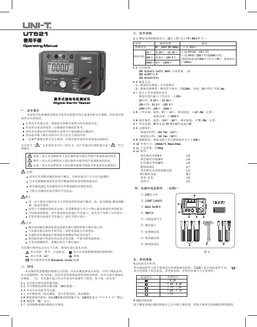
三、技术规格3.1 测量范围和测量误差(20℃±5℃及≤75%RH条件下):范围 测量范围 精度接地电压0V~200V(50/60Hz) ±(1.0%+4)±(2.0%+10) (20Ω档)±(2.0%+3)(200Ω档或2000Ω档)(辅助接地电阻500Ω(误差±5%);接地电压≤10Vac)20Ω 0.00Ω~20.00Ω200Ω0.0Ω~200.0Ω2000Ω0Ω~2000Ω接地电阻3.2 应用标准:IEC 61010-1 CATⅢ 600V 污染等级 二级IEC 61557-1,5IEC 61010-2-313.3 测量方式:(1)接地电压测量:平均值响应(2)接地电阻测量:测试信号频率:约820Hz,电流:20Ω档位 约3.2mA3.4 最大工作范围保持误差测量范围内最大工作误差(±30%)20Ω档:5.00Ω~20.00Ω200Ω档:20.0Ω~200.0Ω2000Ω档:200Ω~2000Ω3.5 工作环境:温度:5℃~40℃;相对湿度:≤80%RH(无雾)海拔高度:≤2000米3.6 储存条件:温度:-20℃~60℃;相对湿度:≤75%RH(无雾)3.7 供电电源:9V供电[1.5V(5号碱性电池)*6]3.8 过载保护:接地电阻档:200 Vac (10秒)接地电压档:400 Vac (30秒)3.9 绝缘阻抗:测量电路与外壳绝缘阻抗不小于20MΩ3.10 外形尺寸:160mmx70.5mmx100mm3.11 产品重量:约560g3.12 附件:绿色测试导线5米 1条黄色测试导线10米 1条红色测试导线20米 1条辅助接地钉 2个带有鳄鱼夹的简易测试线 1套5号碱性电池 6节背带/皮套 1套说明书 1张四、仪器外观及配件:(如图1)图 1① LCD显示屏② LIGHT/LOAD键③ HOLD/SAVE键④ TEST键⑤ 功能选择开关⑥ 测试端口⑦ 标准测试线⑧ 简易测试线⑨ 辅助接地钉2.2 具有数据保持和存储功能(20组数据)。
DS203数码杜邦数字存储波形显示器用户指南说明书

DS203 USER’S MANUAL Contents1. IntroductionMajor Features 2 Safety 2 Operation conditions 2 General Inspection 3 Functional Inspection 3 Firmware Upgrade 3 2. Oscilloscope OperationsInterfaces and Buttons 4 Screen Display 5 Fields in the Input Area 6 Fields in the Output Area 6 Fields in the Measurement Area 7 Parameter Menu 7 Disk Menu 9 3. Application ExamplesExample 1. Measure simple signals 10 Example 2. Acquire a single trace 10 Example 3. Measure with cursors 11 Example 4. Compare waveforms 12 Example 5. Save waveform images 13 4. Tips 151.Introduction to DSO203 OscilloscopeDS203 is a pocket size 4-channel digital storage oscilloscope for common electronic engineering tasks. Its CPU is an ARM Cortex M3, STM32VCT6, with an AD9288-40 dual A/D converter sampling at 72 MHz, and a customer FPGA to manage the ADC and data buffering. A built-in 2MB USB disk enables you to store waveforms and to upgrade firmware. It also provides 4 application areas, convenient for users to load and upgrade at most 4 different application firmware. Schematics and source files are open-sourced to encourage improvements and innovations.Major FeaturesThis pocket-size oscilloscope DSO203 helps you test electronic devices, and measure relevant electronic signal. Its features include:∙Full color 3” TFT LCD display, 400x240 pixels.∙8 MHz ADC bandwidth,8-bit precision.∙ 2 analog channels: (CH_A, CH_B) and 2 digital channels (CH_C, CH_D).∙Integrated Square/Sine/Triangle/Sawtooth signal generator.∙Calculation channels: [CH_A]+[CH_B], [CH_A]-[CH_B], Logic OR [CH_C]|[CH_D], Logic AND [CH_C]&[CH_D], REC_A, REC_B, REC_C, REC_D.∙Maximum sampling rate of a single analog channel, 72 MS/s.∙Maximum record length of any channel, 4096 points.∙Waveforms and upgrade firmware can be stored in built-in 2M USB disk.∙Rechargeable battery powered by USB connection.∙Comprehensive user interface through 6 buttons/switches and colored menu control system.∙ 2 mcx 1X/10X oscilloscope probes.SafetyTo ensure your safety & avoid any damage to the device/connected products, please read the following precautions carefully. To avoid any possible dangers, please use this product according to the following rules.∙Avoid fire and physical injury.∙Use supplied USB cord for power.∙Connect and disconnect properly. Do not plug/unplug when the probe(s)/test lead(s) is connected to the voltage sources. Before you plug/unplug current probes, disconnect power to the circuit-under-test.∙Observe all terminal ratings. To avoid fire/electric shock, please observe ratings & symbols on the product. Please read the user’s manual carefully to determine the ratings before connecting the device.∙Do not operate in humid environment.∙Do not operate in inflammable/explosive environment.∙Keep the surface of the product clean and dry.Operation Conditions∙Temperature:Operating Condition:0 to +50°C; Non-operating Condition:-20 to +60 °C.∙Humidity:Operating Condition:high temperature:40 to 50 °C,0 to 60% RH; Operating Condition:low temperature:0 to 40 °C,10 to 90%RH; Non-operating Condition:hightemperature:40 to 60 °C,5 to 60% RH; Non-operating Condition:low temperature:0 to 40 °C,5 to 90% RH∙Electrical Ratings: Max transient voltage, ± 400 V peak; Measure voltage range, ±15 V peak;Max input voltage of logic probe, ±15 V peak; Measurement frequency range, 8 MHz.General InspectionWhen you first receive a new DS203 oscilloscope, inspect it by following steps:1.Inspect shipping damage. If the packaging carton or protection pad is seriously damaged, keepthe package for returning.2.Inspect the oscilloscope. Contact us for following problems: (1) surface of device is damaged; (2)device does not work; and (3) device doesn’t pass pe rformance test. If damage is resulted from shipping, please keep the container and inform the shipping company responsible for shipping this service.3.Call RIGOL distributor to arrange for repair/change.Functional Inspection1.Take DSO203 out of the shipping box and remove plastic wrapping. Return the device if thereare signs of damage.2.Turn on the POWER switch. The homepage of the DSO203 will be displayed.3.If DSO203 does not turn on, connect it to a computer through supplied USB cable to recharge thebattery, until the red charging LED turns off.4.Connect one probe to the WAVE_OUT channel, and another probe to the CH_A channel. Makesure that both probes are set at 1X setting. Turn on DSO203, and it will show the homepage, witha square wave at 20KHz, Vpp=5V.5.Check whether the measured values are consistent with standard values. Check CH_B, CH_Cand CH_D.Firmware UpgradeConnect the DSO203 to your PC with a mini USB cable. Hold down the Run button while turning on DSO203. It is now in firmware upgrade mode, and a USB disk should appear on your PC. Copy the firmware files one at a time. After a file is copied, disconnect DSO203. When DSO203 reconnects, the file you copied will be updated.The order that you upload the files is very important. Start by uploading the .hex files. Their order is not important. To upload the .BIN files, you need to first upload the corresponding .ADR file. This tells DSO203 where to put the binary file. Upload CFG_FPGA.ADR first, and then upload xxxxFPGA.BIN immediately after. If you make a mistake, delete all the files and start again.When you're finished uploading all the firmware files, turn off DSO203 to complete the upgrading. When you boot up DSO203 again, your firmware should be updated. If you get an error message screen, try uploading the firmware again, carefully following the instructions above.To upgrade the firmware, please follow these steps:1.Open Web to access , download the latest firmware of your oscilloscope toyour PC.2.Hold down the RUN/HOLD switch of DS203 and simultaneously turn on POWER to enterDFU Firmware Upgrade Mode.3.Connect DS203 to your PC through the supplied USB cable. A removable disk named “DFUV3_10_D” will appear on your PC. Copy the firmware to the root directory of this disk. Restart DS203 and the firmware is upgraded.2. Operating DSO203 OscilloscopeInterfaces and Buttons.DSO203 is a pocket size Digital Storage Oscilloscope, measured about 4”x2-1/2”x1/2”. Its front view and side views are shown in the following figure:On the top edge, there are four buttons, as seen from left to right: Run , Disk ■, Parameter ●,Jump ▲; and then two rocker switches: Select , and Navigate ).On the left side, there are three sockets. From top to bottom, they are Wave Output (WAVE OUT), Analog Channel B Input (CH_B), and Analog Channel A Input (CH_A).On the right side, from top to bottom, there are two sockets for Digital Channel C Input (CH_C), Digital Channel D Input (CH_D), a Mini USB port, and a Power Switch.Functions of these buttons, switches and sockets are summarized in the following table:Screen DisplayDSO203 has a 3” full color TFT LCD display to show waveforms and all relevant information. It is a challenging task to place all the information on such a small display, and it is also difficult for the user to navigate through the maze of menus and functions with only 6 buttons.When DSO203 is turned on, a very busy screen is flashed on the screen as shown below:A large area in the middle of the DSO203 screen is dedicated to display 4 colored waveform traces: a blue trace for Channel A, a yellow trace for Channel B, a purple trace for Channel C and a green trace for Channel D. The color coding is very important and very convenient. There are many fields with alphanumeric information displayed in color. If a field is related to the four input channels, it has the corresponding color to give you a clue as to the attributes of this particular field.The four heavy colored signal traces are displayed on a black background with very light grids in5mm spacing. In addition, there are 6 cursors in single pixel dotted lines. Two horizontal cursors show voltages V1 and V2. One horizontal cursor shows the triggering level THR. Two vertical cursors show timing marks T1 and T2. A third vertical cursor shows the triggering point T0.On the top edge of the display is an Input Area, divided into 6 fields from A to F, showing attributes of these 4 traces, and an Output Area from G to I, showing attributes of the output wave sent out of the output socket. On the right edge is the Measurement Area, divided into 11 fields from J to T, allowing parameters to be selected and to be modified. On the bottom is the Parameter Area, divided into 4 fields from U to W, showing values of parameters selected for displaying.The rocker switch Navigate is used to navigate through these fields in the Input, Output andMeasurement Area. The cursor is a currently selected field, flashing on and off to indicate that it is selected and ready for change. The rocker switch Select is then scrolled left or right to change value in the selected field.Navigate only moves the selected fields within one area. The Jump ▲ button allows jumping from one area to another.Once jumped into an area, the Navigate switch will only move selected Menu in the same area, until the Jump Button is pressed.To enter the Output Area to change fields H and I, you must first move to Field G and then press the Select switch to navigate among the G-I fields in the Output Area. Then scroll the Select rocker switch left or right to change values.The Fields B to F in the Input Area have upper and lower halves. Hold down the Select switchfor 2 seconds will switch between the upper and lower halves. Then scroll the Select rockerswitch left or right to change its value.The lower part of the Output Area shows the current contents of the memory buffer. A rectangle shows the portion of the memory buffer which is currently displayed on the DSO screen. This rectangle can be moved using the T0 field in the Measurement Area.Fields in the Input AreaFields and their functions in the Input AreaFields in the Output AreaFields and their functions in the Output Area Navigate only moves the selected menu between B and G. To move to Menus H and I, firstmove to Menu G and then press the Select switch to navigate among the G-I Menus.Fields in the Measurement AreaFields and their functions in the Measurement Area: Pulse and level Scroll to choose channel (different colors). Scroll ress Scroll to choose channel (CH_A/CH_B/ CH_C/CH_DScrollto choose channel (CH_A/CH_B/ CH_C/CH_D Scroll to adjust time maker T1. Press Scroll to hide time marker T2.Scroll to choose channel (CH_A/CH_B/CH_C/CH_DScroll Scroll Scroll to exit Measurement Area.There are 8 triggering modes in Field J:Parameter MenuThe following figure below shows a typical signal trace. Insert one probe into the WAVE OUTsocket, and another one into the CH_B socket. Make sure that the probe switches are set to 1X. Scroll Navigate to Menu G. Scroll to select a square wave output. Press tonavigate to Menus H and I, and scroll to select 1KHz frequency, and 50% duty cycle.Now, press ●button shortly to display current parameter list, as shown in this figure:The Parameter List contains the following items and their current values:There are 12 parameters. Only 9 parameters can be displayed at a time. Short press ● button shows only the current 9 parameters. To see other parameters, hold down ● for 2 seconds and a narrower parameter list appears. Scroll to select a parameter you no longer need, and then press to choose a parameter you want to see. You can therefore select another set of 9 parametersto view. Make sure that EXT is selected. Scroll to EXT, and hold down . The narrow parameter list will disappear. Next time you short press ● button, the parameter list you chose will appear.Press or choose EXT to exit.Disk MenuPress ■ button to access the Disk Menu. Press it again to exit. Detailed functions are listed below:Press Scroll to choose file. Press to confirm. Scroll to choose file. Press to confirm. Scrollto choose file. Press to confirm. Scroll to choose file. Press to confirm. Scroll to choose file. Press to confirm. Scroll to choose file. Pressto confirm.ScrollScroll to adjust buzzer volume. Press Pressto calibrate. Press3. ExamplesExample One:Measure simple signalsIt is very easy to observe unknown signals in a circuit with DSO203. You can see the signal traces, and measure the frequency and peak-to-peak values of the signal.In this simple example, following these steps:1.Insert a probe into the WAVE OUT socket on your DSO203..2.Insert a probe Into CH_B analog input socket. Connect these two probes.3.Set output waveform to square wave in G field, 20 KHz in Hfiel, and 50% duty cycle in I field.4.Select DC coupling for CH_B in upper C field, and select a 2V voltage level in lower C field.5.Select AUTO display mode in upper F field, adjust the sampling time to 20uS in lowerF field.Make sure that the signal trace is displayed clearly.6.Select a proper trigger mode in J field. Here, . Make sure the cursor is yellow.7.Adjust trigger level THR in K field to display a stable trace. THR must be yellow also.8.Press Parameter ●button to see a parameter list. Observe signal parameters, e.g.:Vpp (peak-to-peak voltage), RMS (average value of voltage), FRQ (frequency) and so forth.Your should see the following screen display:Example Two: Acquire a Single TraceIt’s the most important feature of a digital storage oscilloscope to acquire non-periodic signals like pulses and spikes. To acquire a single signal trace, you need a priori knowledge of it to set the proper trigger level and trigger edge. For example, if the pulse is a TTL logic signal, trigger level should be set as 2V, trigger edge as rising edge. If the signal is not stable, you should observe it in a AUTO display mode to find the proper trigger level and trigger edge.Operation procedure is as following:1.Connect a probe from CH_B to a test point in you circuit.2.Select single trace display mode, SINGL (F upper).3.Select DC coupling for CH_B (C upper).4.Select rising edge trigger (J).5.Adjust horizontal time level (F lower) and voltage scale (C lower) to proper ranges.6.Adjust trigger level in THR (K).7.Press , and wait for properly trigger signal to appear. If a signal reaches preset trigger level, asignal trace will be displayed.This procedure can catch occasional events very easily, such as. a sudden spike of high amplitude. Set the trigger level a little bit higher than normal signal level, press , and wait for the spike. DSO203 will automatically trigger and store the waveforms before and after the triggering event. It’s shown in the figure below. You can observe the waveforms before and after the triggering event.Example Three: Measurements with CursorsThere are several measuring cursors in DSO203. They are displayed a narrow dotted horizontal and vertical lines across the display screen. They are used to measure the time and voltage in the signal traces.The following figure shows a typical analog signal trace. You can do two exercises with this trace. Measure the cycle time of the 3rd waveform from the signal trace.Follow these steps:1.Navigate to T1 in N field. Change its color to yellow.2.Scroll , move cursor T1 to the 3rd peak of the trace.3.Navigate to T2 in O field. Change its color to yellow.4.Scroll , move cursor T2 to the 4th peak of the trace.5.Read △T=14.0uS, in the W field of the Parameter Area.Measure the peak-to-peak voltage of the signal trace.Follow these steps:1.Navigate to V1 in L field. Change its color to yellow.2.Scroll , move cursor V1 to the top of the trace.3.Navigate to V2 in O field. Change its color to yellow.4.Scroll , move cursor V2 to the bottom of the trace.5.Read △V=168mV in the X field of the Parameter Area.Example Four: Comparison of WaveformsREC_A/ REC_B/ REC_C/ REC_D function in E field can be used to compare a standard signal with an unknown signal.Follow these steps:1.Input a standard signal to CH_A. Press ■, and choose Save Dat 01 to save waveform, as shownin Figure 4.1:2.Input an unknown signal to CH_A. In E field choose REC_A. Press ■, and choose Load Dat, asshown in Figure 4.2:3.Navigate to Y in P field. Adjust horizontal level, to compare waveforms, as shown in Figure4.3:Figure 4.1Figure 4.2Figure 4.3Example Five: Save waveform imagesSometimes waveform images need to be archived and analyzed on PC platform.Follow these steps:1.Acquire a signal trace.2.Press ■ , and choose Save Bmp 01.3.Scroll to choose the correct file number, and then press to confirm.The file (named IMAG001.BMP) will be saved to built-in USB disk; as shown in following figure.To analyze waveform, copy the image file to your PC.4. Operation Tips1.To increase scan speed when measuring high frequency signals, lower buffer depth in S field. Asingle frame of trace has 360 points. Adjust the X value in Q field to observe the bufferedwaveforms in the memory.2.After connecting an input signal, choose AC coupling in the input field to observe noise andripple in the waveform.e cursor V1 and V2 to measure voltage difference.e cursor T1 and T2 to measure time difference.Editor’s NotesWhen the new millennial was upon us, people in the Silicon Valley Forth Interest Group looked at the possibilities of producing a low cost, high performance digital storage oscilloscope. A project was started to build a prototype, but failed miserably. Before 2010, we did not have low power, high speed ADC to push the sampling rate about 1 MHz. We didn’t have low-cost good color LCD’s for displaying waveforms. Microcontrollers didn’t have enough RAM and ROM to support large application programs.Then Seeed Studio brought out the DSO Nano Oscilloscope. Still a bit slow, but quite usable. DSO is just getting better all the time, and now we have DSO203, sampling at 72 MHz. It is the pocket oscilloscope we dreamed about 10 years ago. It is reality.Thanks to those hard working souls in China to bring us this marvelous instrument. The complaints I heard was mostly about the user manual. It’s very small characters are hard to read. It’s Chinglish is difficult to understand. So, I took it on myself to edit the text to make it easier to read. However, I had the fame of writing in Tinglish, and the manual still have rooms for improvements. Your critiques, comments, and suggestions are welcome.Dr. Chen-Hanson Ting156 14th AvenueSan Mateo, CA 94402 USA002-1-650-571-7639***************.。
- 1、下载文档前请自行甄别文档内容的完整性,平台不提供额外的编辑、内容补充、找答案等附加服务。
- 2、"仅部分预览"的文档,不可在线预览部分如存在完整性等问题,可反馈申请退款(可完整预览的文档不适用该条件!)。
- 3、如文档侵犯您的权益,请联系客服反馈,我们会尽快为您处理(人工客服工作时间:9:00-18:30)。
5-2.直流电流测量 ⑴. 将功能开关置于“DCA”位置上; ⑵. 钳口未夹住导线前请按下 0ADJ 开关超过 2 秒使显示屏归零(少于 2 秒将启动数据保留功能),0 ADJ 开关仅适用于 DC40A 量程。 ⑶. 按下扳手使钳口张开,套在 1 根被测导线上(钳口中央位置)。 ⑷. 读取测量值。 注意:若电流从仪器上侧流向下侧,则读数显示“+”,反之,读数为“-”。
6.电压测量
危险 ● 为避免触电事故或仪器损坏,请勿在 AC600V 以上回路中使用。 ● 打开电池盖时请勿测量。 6-1.交流电压测量
⑴. 将功能开关置于“ACV”位置。 ⑵. 将红色测试导线插入 V/Ω 端口,将黑色测试导线插入 COM 端口。 ⑶. 将测试导线的另一端连接被测电路,读取显示值。 6-2.直流电压测量 ⑴. 将功能开关置于“DCV”位置上。 ⑵. 将红色测试导线插入 V/Ω 端口,将黑色测试导线插入 COM 端口。
9.电池更换
警告 ● 为避免触电事故,更换电池前请将功能开关设置为 OFF,且取下测试线。
● 请勿将新旧电池混合使用。
注意
● 安装时请注意电池电极方向。
` 电池电压警告“BAT”显示时,请更换电池,请注意电池完全耗尽时显示消失且不显示“BAT”。
⑴. 设置功能开关至“OFF”位置。 ⑵. 拧开仪器背面电池盖的螺丝,打开电池盖。 ⑶. 更换电池,2 节 R03(UM-4)1.5V 干电池。
必须严格遵守上述操作说明。
如不遵守,测量时可能会导致人身伤害和仪器毁坏。
仪器上 标志,提醒用户在操容。
危险:表示操作不当会导致严重或致命的伤害。 警告:表示操作不当存在导致严重或致命的伤害的可能性。 小心:表示操作不当有可能会导致人身伤害或仪器毁坏。
● 电源: R03 或相等电量(DC 1.5V)电池×2 ● 电流消耗: 约 15mA(ACA,DCA 量程) 约 5mA(ACV,DCV,Ω 量程) ● 自动关闭电源: 打开约 10 分钟后自动关闭电源(耗电量约 35µA) ● 安全规格: 设计符合国际安全规格
IEC61010-1 CAT. III300V / CAT. II60V,污染度 2 IEC61010-2-031、IEC61010-2-032 ● 过载保护: AC 电流范围:每 10 秒 480A AC/DC AC 电压范围:每 10 秒 720V AC/DC 电阻范围: 每 10 秒 300V AC/DC ● 耐压: 3700V AC(有效值,50/60Hz)/分钟 (电气回路和外箱间) ● 绝缘电阻: 1000V 时最小 10mΩ(电气回路和外箱间) ● 钳口尺寸: 直径最大约 30mm ● 体积: 187(L)×68.5(W)×38.5(D)mm
危险 ●切勿测量电压大于 600V AC/DC 的电路。 ●请勿在充满可燃性气体的环境里进行测量。可能会产生火花引起爆炸。 ●钳口采用不会造成被测物短路的设计,但测量非绝缘导线时请注意避免造成短路。 ●请勿在仪器表面或手潮湿的情况下连接测试线或探棒。 ●测试时,请勿进行超量程输入。 ●测量时,请勿打开电池盖。
使用说明
扳手
钳口
数据保留开关 功能开关 显示屏
钳形电流表 MODEL 203
1. 特点
● 设计符合国际安全规格 IEC61010.CAT. III 300V / CAT. II 600V,污染度 2。 ● 数据保持功能,便于在光线昏暗处或不易读数处测量。 ● 自动关机功能,可避免忘记关机,延长电池寿命。 ● 蜂鸣导通检验。 ● 提供全刻度 4000 计数测试量程。
● 钳口的保护设计提高使用安全性。
2. 安全警告
仪器根据 IEC61010(电子测量仪器安全要求)设计、制造并在最佳状态下出厂。 本说明书包含警告和安全规则,记载了避免人身伤害事故和保持仪器能在长期良好状态下使用的注意事项。
因此,使用仪器前请仔细阅读操作指南。
警告 ● 使用前,通读并理解说明书中的操作指南。 ● 请将说明书随身保存以确保可随时参阅。 ● 请严格遵守说明书中指定的产品使用方法进行操作。 ● 理解并遵守安全操作指示。
⑶. 将测试导线的另一端连接被测电路,读取测量值。
7.电阻测量
● 请确保被测回路未通电。
危险
● 打开电池盖时请勿测量。
⑴. 将功能开关置于“Ω/…”位置上。
⑵. 将红色测试导线插入 V/Ω 端口,将黑色测试导线插入 COM 端口。
⑶. 请确认此时显示“OL”,使测试线短路,确认显示读数“0”并且蜂鸣器发出“嘟嘟”声。 ⑷. 被测电阻的两端连接测试线,读取测量值,测试值在 50Ω 以下发出蜂鸣声。
● 重量: 约 200g(包括电池) ● 附件: 测试线、R03 电池×2、使用说明书
4. 测量准备
4-1.电池检查 将功能开关置于“OFF”以外的位置,检查电池电压。如果显示屏没有显示“BAT”,则表示电池状态良好;
显示“BAT”或无法显示,请更换新电池(参照第 9 项更换电池)。 注意:功能开关在“OFF”以外位置时显示也可能消失。这是由于自动关机功能启动后自动切断电源。若要继
注意 ● 测量前请确保功能开关调整到适当位置。 ● 使用测试线或探棒时请确认完全插入端口。 ● 电流测量时请确保取下测试线。 ● 请勿将仪表暴露在阳光、高温、潮湿、露水的环境里。 ● 使用后必须将量程开关设置为 OFF,长期不使用或储藏时,请取下电池。 ● 请勿使用研磨剂或有机溶剂进行清洗,必须使用中性洗剂或湿抹布清洗。
3. 规格
测量范围和精确性(23±5℃,相对温度 45-75%) AC 电流(A)自动量程(50/60Hz)
测量范围
精度
40A
0—40.00A
±3.0%rdg±8dgt
400A
15.0—299.9A
±3.5%rdg±6dgt
300.0—400.0A
±4.0%rdg±6dgt
DC 电流(A) 自动测量
续使用,请将开关调整为“OFF”后调节至所需量程或按任何键,如果还是没有显示值,则说明电池耗尽,请更 换电池。
4-2.开关的设定、操作确认 请确认功能开关是否设定正确,数据保持开关是否工作。否则无法获得所需测量结果。
5. 测量
警告 ● 为避免触电事故,请勿在 AC600V 以上回路中使用。否则可能造成仪器损坏或人身伤害事故。 ● 钳口采用不会造成被测物短路的设计,但测量非绝缘导线时请注意避免造成短路。
△注意
● 即使测试线短路,显示仍可能不完全为 0,这是测试线本身电阻造成的,并非不良。 ● 测试线开路时显示“OL”。
8. 其它功能
8-1.自动关机功能 注意:即使睡眠方式下仍需消耗少量电量。使用完毕后,确保功能开关放置在“OFF”位置上。 ⑴. 自动关机 此功能是为避免忘记关机造成的电池消耗,以延长电池寿命。仪器开机后约 10 分钟,进入自动关机 状态,如需再次测试,请将开关设置为“OFF”或按下数据保留开关后从自动关机状态中返回即可。 ⑵. 解除自动关机 解除自动关机,数据保留开关按下的同时打开电源。此时,开机约 3 秒后,显示屏显示出“P.OFF”。 启用自动关机,关闭电源,在未按数据保持开关的状况下打开电源。
测量范围
精度
400V
0—400.0V
±1.5%rdg±5dgt
600V
150—600V
电阻(Ω/导通) 自动测量(导通蜂鸣 50Ω±35Ω)
测量范围
精度
400Ω
0—400.0Ω
±2.0%rdg±5dgt
4000Ω
150—4000Ω
● 操作系统: 双集成系统 ● 显示: 液晶显示最大数 4199 ● 低电量显示: 显示屏显示出“BAT” ● 超出范围显示: 显示屏显示出“OL” ● 响应时间: 约 2 秒 ● 采样率: 每秒约 2.5 次 ● 精确性温湿度:23±5℃,相对最大湿度 85%,无冷凝作用 ● 操作温湿度:0~40℃,相对最大湿度 85%,无冷凝作用 ● 存储温湿度:-20~60℃,相对最大湿度 85%,无冷凝作用
● 打开电池盖时请勿测量。
● 连接测试线时请勿进行电流测量。
注意:
◆
请保持钳型传感器完全合拢,否则,测量值将不准确,仪器可测量的导体最大直径为
30mm;
◆
当测量较大电流时,会发出蜂鸣声,但不会影响测量,是正常现象。
5-1.交流电流测试
⑴. 将功能开关置于“ACA”位置;
⑵. 按下扳手使钳口张开,套在 1 根被测导线上(钳口中央位置); ⑶. 读取显示值。
⑷. 盖上电池盖并拧紧螺丝。
电池盖
R03 或 UM-4×2
上海亿平仪器仪表有限公司
上海市浦东新区新金桥路 1088 号 A 座 1009 室 电话:021‐61728735 传真:021‐61294372 网址: 邮箱:sales@
警告 ●请勿在非正常情况下进行测量,例如:仪器机体损坏,仪表或测试线金属部件的裸露。 ●测试线或探棒连接在被测物上时,请勿切换量程开关。 ●请勿在仪器上安装替换部件或对仪器进行改造。如果仪器损坏,请将其返回当地经销商进行检修。 ●仪器表面潮湿的情况下,请勿更换电池。 ●请将量程开关转到“OFF”并取下测试线后,打开电池盖更换电池。
8-2.数据保持功能 锁定显示值的功能。按下数据保持开关可保留当时数据。即使输入值变化显示不变。显示屏左上部显示 符号“H”,再按数据保留开关可解除数据保持模式。
注意: ● 在数据保持模式中进入睡眠模式时,将自动解除数据保留。 ● DC40A 量程中若按数据保留开关超过 2 秒将启动 0ADJ 功能。
测量范围
精度
40A
0—40.00A
±3.0%rdg±8dgt
400A
15.0—299.9A
±3.5%rdg±6dgt
300.0—400.0A
±4.0%rdg±6dgt
AC 电压(V) 自动测量(50/60Hz)