摆线液压马达
液压马达原理是什么
液压马达原理是什么
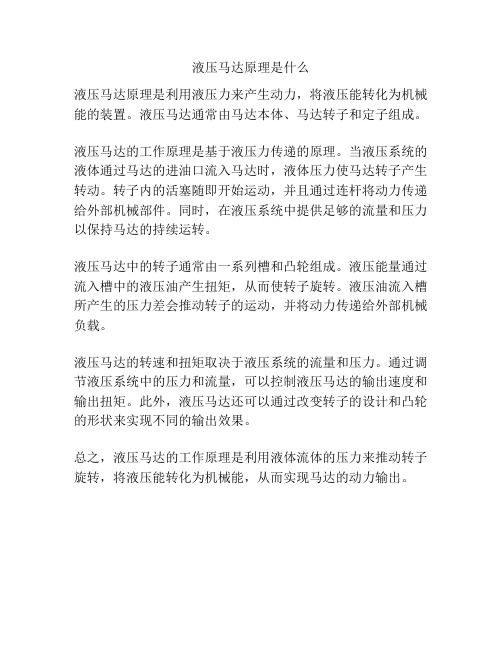
液压马达原理是利用液压力来产生动力,将液压能转化为机械能的装置。
液压马达通常由马达本体、马达转子和定子组成。
液压马达的工作原理是基于液压力传递的原理。
当液压系统的液体通过马达的进油口流入马达时,液体压力使马达转子产生转动。
转子内的活塞随即开始运动,并且通过连杆将动力传递给外部机械部件。
同时,在液压系统中提供足够的流量和压力以保持马达的持续运转。
液压马达中的转子通常由一系列槽和凸轮组成。
液压能量通过流入槽中的液压油产生扭矩,从而使转子旋转。
液压油流入槽所产生的压力差会推动转子的运动,并将动力传递给外部机械负载。
液压马达的转速和扭矩取决于液压系统的流量和压力。
通过调节液压系统中的压力和流量,可以控制液压马达的输出速度和输出扭矩。
此外,液压马达还可以通过改变转子的设计和凸轮的形状来实现不同的输出效果。
总之,液压马达的工作原理是利用液体流体的压力来推动转子旋转,将液压能转化为机械能,从而实现马达的动力输出。
摆线马达常识
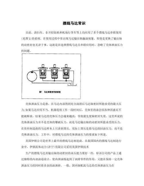
摆线马达常识目前,清扫车、非开挖钻机和机场行李车等上均应用了多个摆线马达串联使用(见图1)的系统。
在使用过程中常出现马达输出轴漏油现象,即使是更换了输出轴的动密封也无济于事,这就是在选择摆线马达且串联应用时,忽略了壳体泄油压力的问题。
壳体泄油压力是指,在马达内部得到充分润滑后马达轴密封所能承受的最大压力;如果马达应用不当,机器连续工作一段时间后,壳体里的油会因各种因素而不能被释放,结果马达的壳体压力会越来越高,导致最先使轴密封失效。
这里所说的壳体泄油压力并不是壳体的爆破压力,而是马达输出轴的动密封所能承受的压力。
在有些制造商的马达样本上只讲到背压,实际上背压是指马达的回油压力,而不是壳体泄油压力。
工作中,对摆线马达的壳体泄油压力的要求如下所述。
美国伊顿公司是世界上最早的摆线马达制造商。
在我国国内的摆线马达制造行业中,伊顿流体动力(济宁)有限公司采用美国伊顿技术生产的摆线马达其输出轴的动密封的承压能力要好一些,即该公司的产品上通过独特的内部油道设计,使内泄油既起到了润滑零件的作用,又能在保持一定壳体泄油压力的同时将多余的油泄掉。
一般,国内轴配流马达的壳体泄油压力在3.0mpa以下,盘配流马达的在5.0mpa以下,而伊顿流体动力(济宁)有限公司生产的轴配流马达的壳体泄油压力则为7.0-10.0mpa,盘配流马达的为7.0mpa。
这些数据在公司的马达样本中都有明确的说明。
需要注意的是,当马达的壳体泄油(内泄)压力超过其推荐值时,马达壳体外泄口必须接回油箱,否则就会大大影响马达轴密封的寿命,甚至会使轴密封失效,导致输出轴处漏油。
实际工作中并不是不推荐马达串联使用,相反地,为了保证多个执行机构的同步,同时在确保设计质量的前提下合理地降低成本,美国伊顿公司生产的摆线马达极大地改善了壳体的承压能力,如h/s/t系列轴配流马达的壳体泄油压力达到10.3mpa,2000系列盘配流马达的壳体泄油压力达到14.0mpa,有效地提高了马达串联使用的能力,给机器的设计提供了优化方案,降低了泵源的流量,节省了制造成本。
外行星摆线马达结构设计

外行星摆线马达结构设计摘要科学技术飞速发展的今天,机器已经很大程度上代替了人力劳动,解放了人的类的体力劳动,为工业的进一步展注入了源源不断的动力,更是为人类的进步做出了不可磨灭的作用。
然而,正当机器在人类工业发展中产生了举足轻重的作用的同时,又有一个新的问题摆在我们的面前,源动力怎么办,又如何能更好地利用我们身边的自然资源?横在人类进步这一阶梯面前的又是一联串的新产生的问题——如何来产生源源不断的动力?为了解决一系列所涉及的动力源的问题,马达、电动机、内燃机、泵等一系列的动力机就孕育而生了。
液压马达就像是人的心脏一样,为源源不断地输送转换能量和提供能量。
为科技工业的发展作出了不可磨灭的功绩。
采用行星针轮摆线啮合付的一齿差原理和结构的液压马达,又称它为外行星传动机构,它的产生对开拓液压技术应用范围将是一次重大的突破。
它的技术优势明显,具体可分为:优化的液压机械技术、优化的结构创新设计和具有领先的应用技术和较大的拓展性技术。
对此可进行不断的开拓和创新。
可以预见,此结构在不久的将来,应用范围一定会越来越广,对解决中国能源的紧迫感有重大作用。
应用此技术对国民经济发展中节能、节省资源和降低制造成本也会产生一定的影响,对扩大液压机械的应用开拓是一项重大的贡献。
本课题研究内容和任务,就是以一种新型结构的液压泵和马达液力转换能量方式,取而代之是一种大功率,高效率,小体积,低价格的马达。
关键词:摆线马达液力转换机构配油机构孔销机构The Structure Design Of Extrasolar planetscycloid MotorAbstractRapid development of science and technology of today, machines have largely replaced human labor, liberating the people of the class manual for further industrial development into streams of momentum more to the progress of mankind made an indelible role. However, while the machinery in the industrial development of mankind have a pivotal role, we have a new problem in front of us, how do power source, How can we make better use of the natural resources around us? Wang human progress in the face of the ladder is a joint series of emerging issues -- how to generate a constant supply of power? To solve a series involving the source of power, motors, motor, the internal combustion engine, a series of pump power generator on the breed and health. Hydraulic motors is like the heart, a steady supply of energy conversion and energy. For the development of IT industries has made indelible contributions. Using needles round cycloid planetary meshing pay a tooth difference principle and structure of hydraulic motors, also called extrasolar planets drive, Its appearance on the pioneering application of hydraulic technology will be a major breakthrough. Its technical advantages are obvious, concrete can be divided into : optimization of hydraulic machinery technology, the optimum structure with innovative design and the application of leading technology and the development of more technology. This can be carried out continuously and innovation. It can be foreseen that this structure in the near future, the application will become wider. China to solve the energy of urgency a major role. Application of this technology to the development of the national economy energy, save resources and reduce the cost of manufacturing will have a definite impact Hydraulic machinery to expand the application development is a major contribution. The research content and the task is to a new structure of the hydraulic pump motors and hydraulic energy conversion, Instead of a high power, high efficiency, small size, low price of motors.Key word:cycloid motor Hydraulic Converter Distribution oil sector Kong marketing agencies目录前言 (1)1.概述 (3)1.1液压马达 (3)1.3摆线马达的相关问题 (4)2.摆线及其相关的问题 (10)2.1问题的提出 (10)2.2摆线的定义与研究历史 (10)2.4摆线的两个重要性质 (12)2.5摆线的其他有关方面 (13)3.摆线轮的结构与工作原理及其分析计算 (15)3.1概述 (15)3.2啮合原理 (16)3.3摆线轮的啮合特性 (18)3.4摆线针轮作用力的理论分析 (23)3.5摆线针轮的齿面接触强度的理论分析 (26)4. 摆线轮机构及其相关部分机构的方案设计及其计算 (29)4.1参数方案选择设计 (29)4.2实际参数设计计算 (33)5.其它部分设计分析 (38)5.1参数选择分析与计算 (38)5.2 柱销与孔的作用力分析 (40)5.3螺栓分析与计算 (42)5.4 轴承的设计计算 (45)5.5壳壁主要部分的设计计算 (48)5.6封密装置的设计分析 (49)结束语 (51)致谢 (51)参考文献 (52)附录 (53)前言浙江是中国海岸线最长、岛屿最多的海洋大省。
摆线马达的优点和缺点分析

摆线马达的优点和缺点分析摆线马达是一种常见的电机类型,其特点是结构简单、效率高、运行平稳,因此在工业和家用电器等领域广泛应用。
然而,摆线马达也存在一些缺点。
本文将对摆线马达的优点和缺点进行详细分析。
首先,我们来看摆线马达的优点。
1. 结构简单:摆线马达由连续圆弧齿轮和滚子组成,没有传统马达的转子和定子部分。
这种简化的结构使得摆线马达具有更高的可靠性和更低的维护要求。
同时,摆线马达的结构简单也意味着制造成本相对较低。
2. 高效率:摆线马达采用滚子与连续齿轮的啮合方式,摩擦损失较小,可以在高转速下运转。
相比其他类型的电机,摆线马达的功率损耗较小,效率更高。
高效率的特性使得摆线马达在节能环保的社会背景下得到广泛应用。
3. 运行平稳:摆线马达的连续齿轮和滚子啮合方式保证了平稳的运转。
相比其他类型的电机,摆线马达在高转速下也能保持稳定的输出转矩,不易产生震动和噪音,能够满足高精度、高稳定性的应用需求。
4. 高扭矩:摆线马达的结构设计使得其在相同尺寸下能够提供更高的输出扭矩。
这一特点使得摆线马达在需要较大驱动力矩的应用中具有优势,比如工业机械、车辆驱动等领域。
然而,摆线马达也存在一些缺点。
1. 体积较大:与其他类型的电机相比,摆线马达的结构需要较大的空间。
由于其采用连续齿轮与滚子的啮合方式,需要一定的间隙,这导致摆线马达相对于同功率的其他电机来说体积较大。
这在一些空间有限的应用中可能会受到限制。
2. 转速受限:摆线马达的运行速度受到限制,通常在2000转/分钟以下。
尽管摆线马达在低速、高扭矩应用中表现出色,但在高速应用中可能无法达到要求。
因此,在高速、大功率应用中,摆线马达可能不是最佳选择。
3. 需要准确的制造工艺:摆线马达的制造工艺要求较高,特别是连续齿轮的加工和组装。
如果制造工艺不精确或装配不当,可能会导致摆线马达的运行不稳定、噪音增加或寿命缩短。
4. 转矩波动:由于摆线马达基于连续齿轮和滚子的啮合方式,其转矩输出随运行位置的变化而波动。
摆线马达原理

摆线马达原理摆线马达,又称为直线马达,是一种利用摆线齿轮传动的电机。
它的工作原理是通过摆线齿轮的转动来驱动负载,具有结构简单、运行平稳、噪音小等优点,因此在各种机械设备中得到广泛应用。
摆线马达的工作原理主要包括摆线齿轮传动原理和电磁感应原理。
首先,摆线齿轮传动原理是摆线马达能够实现直线运动的关键。
摆线齿轮是一种特殊的齿轮,其齿轮轮廓呈现出摆线曲线,而不是常见的圆弧形状。
当摆线齿轮转动时,齿轮的齿尖和齿谷会与传动副中的齿轮齿齿相接触,从而实现直线运动。
这种设计使得摆线马达能够在工作时产生平稳的直线推动力,适用于需要高精度直线运动的场合。
其次,摆线马达的工作原理还涉及到电磁感应原理。
在摆线马达中,电磁线圈和永磁体是两个主要的电磁元件。
当电流通过电磁线圈时,会在线圈周围产生磁场,而永磁体则提供了一个恒定的磁场。
根据洛伦兹力的原理,当电磁线圈中的电流与永磁体的磁场相互作用时,就会产生一个力,从而驱动摆线齿轮的转动。
通过控制电流的大小和方向,可以实现对摆线马达的速度和方向进行精确控制。
摆线马达的工作原理使得它在工业自动化、数控机床、医疗设备、机器人等领域得到了广泛应用。
例如,在数控机床上,摆线马达可以实现高速、高精度的直线运动,从而提高加工效率和加工质量。
在医疗设备中,摆线马达可以驱动X射线机架、CT扫描仪等设备的运动部件,实现精确的位置控制。
在机器人领域,摆线马达可以用于驱动机械臂的关节,实现复杂的运动轨迹。
总的来说,摆线马达的工作原理是基于摆线齿轮传动和电磁感应原理的相互作用。
通过这种工作原理,摆线马达能够实现平稳、高精度的直线运动,具有结构简单、运行可靠的特点,因此在各种领域得到了广泛的应用。
随着科技的不断发展,摆线马达的工作原理也在不断完善和创新,为各种机械设备的性能提升和功能拓展提供了有力支持。
轴配流摆线马达工作原理

轴配流摆线马达工作原理摆线马达是一种特殊的电机,其工作原理包括轴、配流以及流体动力传递。
其工作原理涉及机械结构、流体力学以及电磁学等多个领域,下面我们将详细介绍轴配流摆线马达的工作原理。
轴配流摆线马达是一种基于摆线原理的电机,其最核心的部分即为摆线轮。
摆线轮是一个径向为摆线形状(也称摆线轮)的滚子,其几何形状决定了摆线马达的性能和特性。
在摆线马达中,摆线轮被安放在一个弧度半径较大的偏心摆杆上,因此当摆杆向内、外部偏离时,就会改变摆线轮相对于马达的位置,形成了沿轨迹前进、后退的动作。
这种运动方式相对于传统的电机有许多优势,主要体现在运动平稳、精度高和噪音小等方面。
在摆线马达运转中,配流是至关重要的一环。
配流系统将液压泵传递的液压力转化为摆线轮的运动力,因此配流系统直接影响马达的转速、扭矩以及效率。
摆线马达的配流系统通常由定子、配向板、配向滑块、活塞等部件组成,这些部件的设计和制造直接影响摆线马达的性能和使用寿命。
良好的配流系统设计是摆线马达能够高效工作的关键因素。
摆线马达的核心运动是液压力传递和转换成轴扭矩。
在电机中,液体通过管道进入配向板,然后被引导到摆线轮的不同部分,从而产生了不同的力和力矩。
在液压力作用下,摆线轮围绕自身中心做摆线运动,并通过机械链接转化为轴扭矩。
这种转化过程中,摆线轮产生径向和切向的力矩,从而驱动电机的输出轴旋转,完成能量转换。
摆线马达还有一个重要的工作原理就是对电磁力的利用。
在摆线马达中,电磁线圈通过直流电源产生磁场,而磁场与摆线轮磁材料之间的相互作用产生了电磁力矩。
这种电磁力矩可以调节和控制摆线轮的摆线运动,从而在一定程度上调节电机的输出性能和转速。
总结来看,轴配流摆线马达的工作原理包括轴、配流以及流体动力传递,多个因素共同作用才能使得摆线马达高效工作。
通过对摆线马达工作原理的深入了解,我们可以更好地设计和制造摆线马达,从而发挥其优越的性能和功能。
美国伊顿液压公司产品,内摆线马达维修手册(英文板)

2Geroler MotorsTools required for disassembly and reassembly.l Torque wrench (34Nm [300 Ib-in] capacity)l300-400mm [12-16 inch] breaker barl5/16-12 point socket no. 5422 (Heavy Duty-56Nm [500 Ib-in]capacity)l5/16 12 point socket no. 5422 (Heavy Duty-56Nm [500 Ib-in]capacity)l Small screwdriver (150-200 x 6mm [6-8 x .25 inch] flat blade), seepage 6 for tooling information.l3/16 inch [5mm] hex keyl Shaft pressure seal installation tool for -008 motor P/N 600470l Shaft pressure seal installation tool for -009 and -010 motors P/N600523l Seal sleeve or bullet P/N 600304 (1 inch dia. shaft), P/N 600466The following tools are not necessary for disassembly andreassembly but are extremely helpful.l Small propane torch*T ools available-by special order-through our service department.3Cleanliness is extremely important when repairing these motors.Work in a clean area. Before disconnecting the lines, clean port area of motor. Remove key when used. Check shaft and key slot, remove burrs nicks or sharp edges and polish around the key slot. Before starting disassembly, drain oil from motor, then plug ports and thoroughly clean exterior of motor.Although not all drawings show the motor in a vise, we recommend that you keep the motor in the vise during disassembly. Follow the clamping procedures explained throughout the manual.Disassembly3 Remove cap screws and seal washers from end cap (seal washers used on 59, 69 and 95 cm 3/r [3.6, 4.2 and 5.8 in 3/r] displacement motors only).4 Remove end cap.5 Remove seal from Geroler.6 Remove Geroler-retain rollers in the outer Geroler ring, see Fig. 3.7 Remove seal from Geroler, see Fig. 3.8 Remove drive spacer (not used on 95 and 159 cm 3/r [5.8 and 9.7in 3/r ] displacement motors for the -008 and -009 motors and not used on -010 motors).1 Place motor in vise, clamp across edge of flange with output shaft down. When clamping, use protective device on vise, such as special soft jaws, pieces of hard rubber or board, see Fig. 1.2 Some motors may have a case drain plug in the end cap. If external case drain is not used, it is not necessary to replace the seal unless leakage occurs.Figure 14Figure 3Figure 25Disassembly9 Remove spacer plate 10 Remove drive, see Fig. 4.11 Remove seal from housing.14 Remove motor from vise. Place on clean flat surface. Carefully lift flange from housing with a twisting motion.The screws will require approximately 34-45Nm [300-400 Ib-in] of torque to break loose and approximately 11 Nm [100 Ib-in] torque to remove after they are broken loose. Do not use an impact wrench on Loctited screws, this may result in rounded heads or broken sockets.NOTE: If higher torque than given above is required to break the screws loose, apply heat according to the following instruction. When heated the Loctite partially melts and the torque required to remove the screw is greatly reduced. Follow the instructions carefully , and be careful not to overheat and cause damage to the motor. Use a small flame propane torch to heat a small area of the housing, where the screw enters, see Fig. 6. Apply torque to the screw with a socket wrench gradually as heat is applied for 8 to 10 seconds. As soon as the screw breaks loose, remove heat from the housing and continue turning the screw until it is completely removed.Figure 6Figure 5Clamp across portsnot across housing. Excessive clamping pressure causes distorsion.12 Reposition motor in vise. Clamp across ports as shown in Fig. 5,not on side of housing. Do not over tighten jaws. Excessive clamping force may distort housing.13 Remove the 4 cap screws from the mounting flange. These motors are assembled using Loctite on the screws to hold them in place.Figure 4Disassembly15 The dust seal, pressure seal and oil seal will come off with the flange. Use a seal remover tool, like the one shown in Fig. 7, to remove the dust seal and pressure seal, as shown in Fig. 8 and 9. Work nose of tool between pressure seal and flange. Pry seal partway. Remove tool and repeat at a point 180° away. Push seal completely out of cavity, see Fig. 8.Figure 7Figure 8Figure 10Figure 916 Remove output shaft from housing.17 Remove bearing race and needle thrust bearing from shaft.18 Some older housings have plugs. T o remove the plug, use a 5mm [3/16 inch] hex key, inserted through port opening, to push them out.6Reassembly19 If you removed check valves, or plug(s), replace seal(s). Lubricate new seal(s). Install on check valves, or plug(s). Carefully push check valves, or plug(s), in housing until flush with housing face. Do not damage seal(s).20 Lubricate output shaft with clean hydraulic oil, then install shaft in housing.Important: Do not permit oil to get into the 4 tapped holes.Note: To help with timing procedures, a timing dot is machined on output shaft, see figures 18 and 19.21 Install needle thrust bearing then bearing race on shaft. Pull shaft partially out of housing, push all three parts in housing together. The bearing race must rotate freely when in position.Figure 11A. Wash the housing with non-petroleum base solvent to remove oil,grease and debris. Petroleum base solvents may leave residue detrimental to successful Loctiting. Pay particular attention to 4tapped holes on the flange end.Check all mating surfaces. Replace any parts that have scratches or burrs that could cause leakage or damage. Clean all metal parts in clean solvent. Blow dry with air. Do not wipe parts with cloth or paper towel, lint or other matter can get into the hydraulic system and cause damage. Check around the key slot and chamfered area of the shaft for burrs, nicks or sharp edges that can damage the seals when reassembling. Remove nicks or burrs with a hard smooth stone (such as an Arkansas stone). Do not try to file or grind motor parts.Note: Lubricate all seals with petroleum jelly such as Vaseline. Use new seals when reassembling the motor. Refer to parts list (No. 6-125) for proper seal kit number.Important: Do not stretch seals before installing. Cleanliness isextremely important in the successful application of Loctite. Use the following procedures to properly clean all parts.Note: Fully cured Loctite resists most solvents, oils, gasoline,kerosene, and is not affected by cleaning operations.B. Blow dry with compressed air. Clean and dry the tapped holes.Note: It is not necessary to remove the cured Loctite that is securely bonded in the tapped holes; however any loose particles of cured Loctite should be removed.C. Wire brush the screw threads to remove cured Loctite and other debris. Discard any screws that have damaged threads or a corroded,damaged, or rounded head.D. Wash the screws with non-petroleum base solvent. Blow dry with compressed air jet.7Important: Prior to installing high pressure shaft seal it is necessary to break the sharp corner of the flange seal seat, see Fig. 12. Use 400 grit paper to break corner.23 Lubricate I.D. of seal tube and O.D. of shaft pressure seal with a light film of clean petroleum jelly . Align small I.D. end of seal tube with seal seat in mounting flange. Install back-up ring and pressure seal in tube-lips of seal face up-see above. Then insert seal driver in tube to firmly push (by hand with rotating action) seal in seal seat.Important: After installing seal in flange, examine seal condition. If cut, damaged, or improperly installed, you must replace it before continuing reassembly.24 Install dust seal in flange, see Fig. 15. Press the dust seal into place carefully . T o eliminate damage to rubber portion or distortion of metal container use a tool (flat-round face 35-41 mm[1.37 to 1.62 inch]diameter) which provides proper guiding and positioning.25 Install 1.94 inch [50mm] I.D. seal in flange.Mounting Flange Cross-section22 Clean mounting flange of all loose metallic chips, particles, dirt or other contamination, including oil. During cleaning, visually check seal seat in mounting flange for scratches or other marks that mightdamage the pressure seal. Check for cracks in flange that might cause leakage, see Fig. 12.Important: If a pressure seal installation tool is not available,temporarily install flange without seals. Then install 2 cap screws to secure flange to housing. Install seals in flange, and applyloctite, after you reassemble Gerotor end of motor (see step 41 thru 45 page 11).Note: If you have a pressure seal installation tool, continue reassembly, starting with step 23.Figure 12Reassembly26 Apply 3 or 4 drops of Loctite adhesive (Loctite no. 601 sealant) at top of threads in each of 4 holes in housing, see Fig. 14. Do not allow parts with Loctite applied to surface to contact any metal parts other than their proper assembly . Wipe off excess Loctite from housing face,using a non-petroleum base solvent. Do not apply Loctite to threads more than 15 minutes before installing screws. If housing stands for more than 15 minutes, repeat application. No additional cleaning or removal of previous Loctite is necessary.Caution: Do not use excessive amount of Loctite.Figure 148Figure 1331 Install 90mm [3.59 in.] I.D. seal in housing seal groove. Avoid twisting seal.32 Install drive, observe proper timing procedure (Fig. 18).33 Place spacer plate carefully on the housing, align bolt holes.34 Install 90mm [3.59 in.] I.D. seal in Gerotor seal groove, see Fig. 17.Avoid twisting seal.35 Carefully place Gerotor on the spacer plate, see Fig. 17. Observe proper timing procedure, see Fig. 18.Figure 17ReassemblyFigure 1527 Before installing the flange and seal assembly over the shaft, place a protective sleeve or bullet over the shaft. Lubricate space between dust seal and pressure seal, as well as lips of both seals, see Fig. 15.install flange. Rotate flange slowly while pushing down over shaft.Be careful not to invert or damage the seals.28 Clamp motor in vise as shown in Fig. 5, install dry screws and alternately torque immediately to 28Nm [250 lb-in]. If you useprimer, allow to cure for 10-15 minutes, without primer allow 6 hours before subjecting motor to high torque reversals. On all otherapplications you can run the motor immediately . If you use new bolts,make sure they are the correct length, 22mm [.875 inch] under head length, see parts list for correct part number. Longer screws will not permit proper seal between the flange and housing. Install key in key slot of shaft.Geroler End29 Clamp housing in a vise, Gerotor end up. See Step 1 for correct clamping procedure.Important: T o aid installation of seals, apply light coating of clean petroleum jelly, such as Vaseline, to seals before installing.Important: Do not stretch seals before installing.30 Pour approximately 35 cc of clean hydraulic oil in output shaft cavity.Figure 16910ReassemblyTiming ProcedureA. Align shaft timing dot with any bolt hole.B. Install drive. For the 59 and 74 cm ©/r [3.6 and 4.5 in 3/r] displace-ments on the -010 motors, install the wide end of the drive in the output shaft. Install either end of the drive in the output shaft for the -010 motor displacements ranging from 97 to 370 cm 3/r [5.9 to 22.6in 3/r]C. Install spacer plate. Remember which bolt hole was aligned with the shaft timing dot.D. Place gerotor on wear plate, positioning any star point over the bolt hole aligned with the timing dot.E. Rotate gerotor to fine up bolt hole. Se careful not to disengage star from drive or disturb gerotor seal.36 Install drive spacer (not used on 97 and 159 cm 3/r [5.9 and 9.7 in 3/r]displacements on the -008 and -009 motors and not used at all on -010motors). See figure 17.37 Install 90mm [3.59 inch] I.D. seal in Geroler seal groove. Avoid twisting seal.38 Install end cap, see Figures 20 and 21.Standard RotationFigure 18Reverse rotation is obtained by positioning any star valley , rather than any star point, over the aligned bolt hole.Reverse RotationFigure 1939 Install cap screws (and seal washers when required, see informa-tion below) in end cap.On 97 cm 3/r [5.9 in 3/r] displacement motors or less, use seal washers.Pre-tighten all screws to 2-5 Nm[15-40 lb-in]. Make sure Gerolersection seals are properly seated before torquing screws. Then torque screws to 23 Nm[200 lb-in] in sequence, as shown in Fig. 21.On 120 cm 3/r [7.3 in 3/r] displacement motors or larger, omit seal washers. Pre-tighten all screws to 2-5 Nm [15-40 lb-in]. Make sureGeroler section seals are properly seated before torquing screws. Then torque screws to 34Nm [300 lb-in] in sequence, as shown in Fig. 21.43 Install pressure seal flush against bearing race, see Fig 22. Lightly lubricate pressure seal O.D.ReassemblyBolt Torquing SequenceFigure 21Figure 20Note: Steps 41 through 45 cover mounting flange seal installation without using a seal installation tool.40 Clamp motor in vise with output shaft up, see Fig. 23. Remove cap screws and flange.41 Prepare seal seat of flange, see step 22.42 Lubricate dust seal O.D. Install dust seal in flange. Make sure dust seal is flush with flange, see step 24.44 Place a seal sleeve or bullet over shaft. Twist flange down shaft until flush against pressure seal. The pressure seal must enter into seat evenly and gradually . Install 4 cap screws. Gradually and evenly finger tighten cap screws (crisscross pattern). Then use a hand socket wrench to lightly snug tighten screws until flange is flush against housing Do not tighen screws more than one full rotation at a time (crisscross pattern).Pressure Seal Lips Toward RaceFigure 2245 Use a hand torque wrench to gradually and evenly tighten cap screws (crisscross pattern) until they reach 28Nm[250 lb-in]. See important information below.Important: Do not use air socket wrench on cap screws for this type of seal installation.Important: Proper pressure seal installation is important. Y ou must remove cap screws and flange to examine seal condition. If you have cut or damaged the pressure seal, you must replace it with a new one. If seal is in good condition continue flange reassembly—starting with procedure step 24, page 8.Figure 2311For Additional Literature Contact Eaton Corp. HydraulicsDivision 15151 Highway 5 Eden Prairie, MN 55344.l Specifications and performance Data, Catalog No. 11-885l Replacement Part Numbers and Kit Information:S Series Motors — Parts Information No. 6-125.1. Product Number2. Date Code3. Part Name How to Order Replacement Parts Each Order Must Include the Following:103-1000-XXX Numbers 1001 through 1999 Standard Models103-2000-XXX Numbers 2001 through 2999 Motors with Case Drain Port 4. Part Number 5. Quantity of PartsQuality System Certified Product in this catalog are manufactured in an ISO-9001-certified site.Eaton CorporationHydraulics Division15151 Hwy. 5Eden Prairie, MN 55344Telephone 612/937-9800Fax 612/937-7130Eaton Ltd.Hydraulics Division Glenrothes, Fife Scotland, KY7 4NW Telephone 01-592-771-771Fax 01 -592-773-184Eaton GmbH Hydraulics Products Am Schimmersfeld 740880 Ratingen, Germany Telephone 02102-406-830Fax 02102-406-800Copyright Eaton Corporation, 1987, 1993, 1994, 1995, and 1996All Rights ReservedPrinted in USAForm No. 7-116。
液压马达介绍

液压马达介绍液压马达⼀、液压马达定义及⽤途液压马达是将液压能转换成机械能的⼯作装置,以旋转运动向外输出机械能,得到输出轴上的转速和转距。
液压马达主要应⽤于注塑机械、船舶、起重、卷扬等场合。
⼆、按输出转速分为⾼速和低速两⼤类.1、输出转速⾼于500 r/min的属于⾼速液压马达。
它们的主要特点是转速较⾼、转动惯量⼩,便于起动和制动,调速和换向的灵敏度⾼,通常⾼速液压马达的输出转矩不⼤。
2、输出转速低于500r/min的属于低速液压马达。
低速液压马达的主要特点是排量⼤、体积⼤、转速低,因此可直接与传动机构连接,不需要减速装置,使传动机构⼈为简化。
三、液压马达也可按其结构类型分为齿轮式、叶⽚式、柱塞式等。
1、齿轮液压马达齿轮液压马达⼜分为外啮合齿轮马达和内啮合齿轮马达。
齿轮马达具有体积⼩、重量轻、⾃吸性能好、维修⽅便等优点。
但同时齿轮马达也存在压⼒和流量脉动⼤、容积效率和输⼊压⼒较低、输出转矩⼩、噪⾳⼤等缺点。
因此齿轮液压马达仅适合于⾼速⼩转矩的场合。
⼀般⽤于农业机械等对转矩均匀性要求不⾼的机械设备上。
(附齿轮马达动画)2、叶⽚马达叶⽚马达具有体积⼩、流量均匀、运转平稳、噪⾳低、动作灵敏、输⼊转速较⾼等优点;但同时叶⽚马达泄漏量较⼤、低速稳定性较差、输⼊压⼒较低、对油压的清洁度要求较⾼。
因此叶⽚式液压马达⼀般⽤于转速⾼、转矩⼩和动作要求灵敏的场合。
(附叶⽚马达动画)3、摆线马达摆线马达⼯作原理和内啮合齿轮马达相似。
摆线马达采⽤了摆线针轮啮合代替内啮合齿轮的形式。
摆线马达具有体积⼩、重量轻、⾃吸性能好、维修⽅便等优点。
但同时摆线马达也存在压⼒和流量脉动⼤、容积效率和输⼊压⼒较低、输出转矩⼩等缺点。
因此齿轮液压马达仅适合于中、低速⼩转矩的场合。
(附摆线马达原理图)4、径向柱塞式液压马达径向柱塞马达为低速⼤扭矩液压马达。
低速液压马达按其每转作⽤次数,可分为单作⽤式和多作⽤式。
我公司⽣产的XHM、XHS液压马达就是单作⽤径向柱塞马达。
- 1、下载文档前请自行甄别文档内容的完整性,平台不提供额外的编辑、内容补充、找答案等附加服务。
- 2、"仅部分预览"的文档,不可在线预览部分如存在完整性等问题,可反馈申请退款(可完整预览的文档不适用该条件!)。
- 3、如文档侵犯您的权益,请联系客服反馈,我们会尽快为您处理(人工客服工作时间:9:00-18:30)。
摆线液压马达编辑本词条缺少名片图,补充相关内容使词条更完整,还能快速升级,赶紧来编辑吧!
19世纪50年代末期,最初的低速大扭矩液压马达是由油泵的一个定转子部件发展而来的,这个部件由一个内齿圈和一个与之相配的齿轮或转子组成。
中文名摆线液压马达作者中华人民共和国工业和信息化部丛书名冷配在线出版社机械工业出版社出版时间2010-07-01版次1目录1摆线液压马达2优点3国家标准文件? 基本信息
? 内容简介
? 图书目录
1摆线液压马达编辑内齿圈与壳体固定能接在一起,从油口进入的油推动转子绕一个中心点公转。
这种缓慢旋转的转子通过花键轴驱动输出成为摆线液压马达。
这种最初的摆线马达问世后,经过几十年演化,另一种概念的马达也开始形成。
这种马达在内置的齿圈中安装了滚子.具有滚子的马达能提供较高的启动与运行扭矩,滚子减少了摩擦,因而提高了效率,即使在很低的转速下输出轴也能产生稳定的输出。
通过改变输入输出流量的方向使马达迅速换向,并在两个方向产生等价值的扭矩。
各系列的马达都有各种排量的选者,以满足各种速度和扭矩的要求。
2优点编辑摆线液压马达是一轴配流镶齿定转子副式的小型低速大扭矩液压马达,优点如下:
1、体积小,重量轻,它的外形尺寸比同样扭矩的其它类型液压马达小得多。
2、转速范围广,可无级调速,最低稳定转速可达15转/分,安装布置方便,投资费用低。
3、在液压系统中可串联使用,也可并联使用。
4、转动惯性小,在负载下容易起动,正反转都可使用,而且换向时不用停机。
摆线液压马达用途广泛,主要用于农业、渔业、轻工业、起重运输、矿山、工程机械等多种机械的回转机构中。
国外应用摆线液压马达的例子:
1 农业用:各种联合收割机,播种机,旋耕机,割草机,喷雾机,饲料搅拌机,地面钻孔机。
2 渔业用:起网机。
3 轻工业用:卷绕机,纺织机,印刷机,营业用洗涤机。
4 建筑工业用:压路机,水泥搅拌机,清扫车。
二、结构及性能特点
摆线液压马达为输出轴与配流阀一体成型,镶齿式定转子副摆线液压马达,具体结构见图一,主要功能特点:
1 采用了端面配流和轴面配流,结构简单紧凑,配流精度高;
2 采用镶齿定转子副,机械效率高,高压运转寿命长;
3 采用双联角接球轴承,可以承受较大的径向和轴向负载,摩擦力小,机械效率高。
4 先进的配流机构设计,具有配流精度高和磨损自动补偿的特点。
5 马达允许串联和并联使用,串联使用时应接外泄油口。
6 采用圆锥滚子轴承支撑设计,具有较大的径向承载能力,使得马达可直接驱动工作机构。
7 多种法兰、输出轴、油口等安装连接形式。
三、运转注意事项
(1)运转前检查液压系统全部元件是否连接正确,通过滤清器把油加到指定高度。
(2)在无负荷状态下起动运转10~15分钟,并进行排气、油箱中有泡沫,系统有噪音,以及马达油缸有滞进都证明系统中有空气。
(3)排除空气后,加满油箱,再开始给马达渐渐增加负荷,直到最高负荷,观察是否有不
正常现象,如噪声、油升和漏油等。
(4)通过运转50小时更换一次油,以后更换按保养规则进行。
(5)如非马达故障,请不要轻易拆卸。
四、拆卸和装配
泰勒姆斯液压马达故障需要拆装时,请注意以下事项:
(1)拆装时不要碰伤各结合面,如有碰伤,需修整后才能装配。
(2)装配前用汽油或煤油洗净所有零件,禁止使用棉纱或破布擦洗零件,应用毛刷或绸布,切不可将橡胶圈浸在汽油中。
马达装好后,在装机前需往两油口加50~100毫升的液压油,转动输出油,如无异常现象方可装机。
(3)为保证马达旋转方向正确,需注意转子与输出轴的位置关系。
(4)后盖螺栓必须对角渐次拧紧,紧固力矩为4~5公斤力·米。
3国家标准文件编辑基本信息
《摆线液压马达》摆线液压马达作者:中华人民共和国工业和信息化部编
丛书名:冷配在线
出版社:机械工业出版社
ISBN:15111.9596
出版时间:2010-07-01
版次:1
页数:12
装帧:平装
开本:16开
内容简介
《JB/T 102062010 摆线液压马达》轴配流摆线液压马达排量扩充50mL/r、3mL/r两个规格;——标准压力参数中的压力级整体式定子增加14MPa档,组合式定子增加16MPa档,平面配流增加14MPa档和20MPa档;——修改"表3"中容积效率和总效率指标值:——修改"表4"的分组和清洁度指标值;——规范了气密性能试验的方法。
本标准的附录A是规范性附录,附录B是资料性附录。
本标准由中国机械工业联合会提出。
本标准由全国液压气动标准化技术委员会(SAC/TC3)归口。
本标准起草单位:镇江液压件厂有限责任公司。
图书目录
前言
1 范围
2 规范性引用文件
3 术语和定义
4 参量、符号和单位
5 分类和基本参数
5.1 分类
5.2 基本参数
6 技术要求
6.1 一般要求
6.2 性能要求
6.3 装配要求
6.4 外观要求
7 性能试验方法
7.1 试验装置
7.2 试验用油
7.3 稳态工况
7.4 测量准确度
7.5 试验项目和试验方法
7.6 数据处理与结果表述
8 装配和外观的检验方法
9 检验规则
9.1 检验分类
9.2 抽样
9.3 判定规则
10 标志、包装、运输和贮存
附录A (规范性附录)试验回路和特性曲线A.1 试验回路
A.2 特性曲线
附录B (资料性附录)摆线液压马达试验记录表图A.1 试验回路原理图
图A.2 综合特性曲线
表l 参量、符号和单位
表2 基本参数
表3 性能指标
表4 清洁度指标
表5 被控参量平均指示值允许变化范围
表6 测量系统的允许系统误差
表7 形式试验项目和方法
表8 出厂试验项目和方法
表9 马达装配和外观的检验方法。