L298电机驱动芯片资料
L298N的详细资料驱动直流电机和步进电机

L298N的详细资料驱动直流电机和步进电机电机驱动电路;电机转速控制电路(PWM信号)主要采用L298N,通过单片机的I/O输入改变芯片控制端的电平,即可以对电机进行正反转,停止的操作,输入引脚与输出引脚的逻辑关系图为驱动原理图--------------------------------------------------------L298N电机驱动模块图•••1.1 实物图••1.2 原理图•••1.3 各种电机实物接线图•••1.4 各种电机原理图•••1.5 模块接口说明•••L298N电机驱动模块图1.1 实物图正面背面1.2 原理图1.3 各种电机实物接线图直流电机实物接线图4相步进电机实物接线图3相步进电机实物接线图1.4各种电机原理图直流电机原理图步进电机原理图1.5 模块接口说明+5V:芯片电压5V。
VCC:电机电压,最大可接50V。
GND:共地接法。
A-~D-:输出端,接电机。
A~D+ :为步进电机公共端,模块上接了VCC。
EN1、EN2:高电平有效,EN1、EN2分别为IN1和IN2、IN3和IN4的使能端。
IN1~ IN4:输入端,输入端电平和输出端电平是对应的。
1和15和8引脚直接接地,4管脚VS接2.5到46的电压,它是用来驱动电机的,9引脚是用来接4.5到7V的电压的,它是用来驱动L298芯片的,记住,L298需要从外部接两个电压,一个是给电机的,另一个给L298芯片的6和11引脚是它的使能端,一个使能端控制一个电机,至于那个控制那个你自己焊接,你可以把它理解为总开关,只有当它们都是高电平的时候两个电机才有可能工作,5,7,10,12是298的信号输入端和单片机的IO口相连,2,3,13,14是输出端,输入5和7控制输出2和3, 输入的10,12控制输出的13,14L298N型驱动器的原理及应用L298N是SGS公司的产品,内部包含4通道逻辑驱动电路。
是一种二相和四相电机的专用驱动器,即内含二个H桥的高电压大电流双全桥式驱动器,接收标准TTL逻辑电平信号,可驱动46V、2A以下的电机。
【2018-2019】l298n中文资料-实用word文档 (9页)

本文部分内容来自网络整理,本司不为其真实性负责,如有异议或侵权请及时联系,本司将立即删除!== 本文为word格式,下载后可方便编辑和修改! ==l298n中文资料篇一:L298N中文资料L298N电机驱动器使用说明书L298N是ST公司生产的一种高电压、大电流电机驱动芯片。
该芯片采用15脚封装。
主要特点是:工作电压高,最高工作电压可达46V;输出电流大,瞬间峰值电流可达3A,持续工作电流为2A;额定功率25W。
内含两个H桥的高电压大电流全桥式驱动器,可以用来驱动直流电动机和步进电动机、继电器线圈等感性负载;采用标准逻辑电平信号控制;具有两个使能控制端,在不受输入信号影响的情况下允许或禁止器件工作有一个逻辑电源输入端,使内部逻辑电路部分在低电压下工作;可以外接检测电阻,将变化量反馈给控制电路。
使用L298N芯片驱动电机,该芯片可以驱动一台两相步进电机或四相步进电机,也可以驱动两台直流电机。
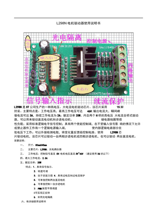
简要说明:一、尺寸:80mmX45mm二、主要芯片:L298N、光电耦合器三、工作电压:控制信号直流5V;电机电压直流3V~46V(建议使用36伏以下)四、最大工作电流:2.5A 五、额定功率:25W特点:1、具有信号指示。
2、转速可调3、抗干扰能力强4、具有过电压和过电流保护5、可单独控制两台直流电机6、可单独控制一台步进电机7、PWM脉宽平滑调速8、可实现正反转9、采用光电隔离六、有详细使用说明书七、提供相关软件八、提供例程及其学习资料实例一:步进电机的控制实例步进电机是数字控制电机,它将脉冲信号转变成角位移,即给一个脉冲信号,步进电机就转动一个角度,因此非常适合于单片机控制。
步进电机可分为反应式步进电机(简称VR)、永磁式步进电机(简称PM)和混合式步进电机(简称HB)。
一、步进电机最大特点是:1、它是通过输入脉冲信号来进行控制的。
2、电机的总转动角度由输入脉冲数决定。
3、电机的转速由脉冲信号频率决定。
二、步进电机的驱动电路根据控制信号工作,控制信号由单片机产生。
L298N中文资料

L298N电机驱动器使用说明书L298N是ST公司生产的一种高电压、大电流电机驱动芯片。
该芯片采用15脚封装。
主要特点是:工作电压高,最高工作电压可达46V;输出电流大,瞬间峰值电流可达3A,持续工作电流为2A;额定功率25W。
内含两个H桥的高电压大电流全桥式驱动器,可以用来驱动直流电动机和步进电动机、继电器线圈等感性负载;采用标准逻辑电平信号控制;具有两个使能控制端,在不受输入信号影响的情况下允许或禁止器件工作有一个逻辑电源输入端,使内部逻辑电路部分在低电压下工作;可以外接检测电阻,将变化量反馈给控制电路。
使用L298N芯片驱动电机,该芯片可以驱动一台两相步进电机或四相步进电机,也可以驱动两台直流电机。
简要说明:一、尺寸:80mmX45mm二、主要芯片:L298N、光电耦合器三、工作电压:控制信号直流5V;电机电压直流3V~46V(建议使用36伏以下)四、最大工作电流:五、额定功率:25W特点:1、具有信号指示。
2、转速可调3、抗干扰能力强4、具有过电压和过电流保护5、可单独控制两台直流电机6、可单独控制一台步进电机7、PWM脉宽平滑调速8、可实现正反转9、采用光电隔离六、有详细使用说明书七、提供相关软件八、提供例程及其学习资料实例一:步进电机的控制实例步进电机是数字控制电机,它将脉冲信号转变成角位移,即给一个脉冲信号,步进电机就转动一个角度,因此非常适合于单片机控制。
步进电机可分为反应式步进电机(简称VR)、永磁式步进电机(简称PM)和混合式步进电机(简称HB)。
一、步进电机最大特点是:1、它是通过输入脉冲信号来进行控制的。
2、电机的总转动角度由输入脉冲数决定。
3、电机的转速由脉冲信号频率决定。
二、步进电机的驱动电路根据控制信号工作,控制信号由单片机产生。
(或者其他信号源)如图:按CTRL并点击(L298N驱动器与直流电机接线图)三、基本原理作用如下:两相四拍工作模式时序图:(1)控制换相顺序1、通电换相这一过程称为脉冲分配。
驱动芯片L298N的介绍

驱动芯片L298N的介绍-CAL-FENGHAI.-(YICAI)-Company One1驱动芯片L298N的介绍L298是SGS(通标标准技术服务有限公司)公司的产品,比较常见的是15脚Multiwatt封装的L298N,内部包含4通道逻辑驱动电路。
是一种二相和四相电机的专用驱动器,即内含二个H桥的高电压大电流双全桥式驱动器,接收标准TTL逻辑电平信号,可驱动46V、2A以下的电机。
其引脚排列如上图中所示。
:L298N的引脚9为LOGIC SUPPLY VOLTAGE Vss,即逻辑供应电压。
引脚4为SUPPLY VOLTAGE Vs,即驱动部分输入电压。
Vss电压要求输入最小电压为4.5V,最大可达36V;Vs电压最大值也是36V,但经过我的实验,Vs电压应该比Vss电压高,否则有时会出现失控现象。
它的引脚2,3,13,14为L298N芯片输入到电动机的输出端,其中引脚2和3能控制两相电机,对于直流电动机,即可控制一个电动机。
同理,引脚13和14也可控制一个直流电动机。
引脚6和11脚为电动机的使能接线脚。
引脚5,7,10,12为单片机输入到L298N芯片的输入引脚。
下表是其使能、输入引脚和输出引脚的逻辑关系:EN A(B)IN1(IN3)IN2(IN4)电机运行情况H H L正转H L H反转H同IN2(IN4)同IN1(IN3)快速停止L X X停止控制使能引脚ENA或者ENB就可以实现PWM脉宽速度调整。
1脚和15脚可单独引出连接电流采样电阻器,形成电流传感信号,也可以直接接地。
在可设计中就将它们直接接地。
L298N是内含二个H桥的高电压大电流双全桥式驱动器可驱动46v,2A以下电机,1和15脚可单独引出接电流采样电阻器,形成电流传感信号.接错无法控制电机.引脚8为芯片的接地引脚,它与L298N芯片的散热片连接在一起。
由于本芯片的工作电流比较大,发热量也比较大,所以在本芯片的散热片上又连接了一块铝合金,以增大它的散热面积。
L298简介
L298简介2010-05-23 06:41L298N 为SGS-THOMSON Microelectronics 所出产的双全桥步进电机专用驱动芯片( Dual Full-Bridge Driver ) ,内部包含4信道逻辑驱动电路,是一种二相和四相步进电机的专用驱动器,可同时驱动2个二相或1个四相步进电机,内含二个H-Bridge 的高电压、大电流双全桥式驱动器,接收标准TTL逻辑准位信号,可驱动46V、2A以下的步进电机,且可以直接透过电源来调节输出电压;此芯片可直接由单片机的IO端口来提供模拟时序信号,但在本驱动电路中用L297 来提供时序信号,节省了单片机IO 端口的使用。
L298N 之接脚如图9 所示,Pin1 和Pin15 可与电流侦测用电阻连接来控制负载的电路; OUTl、OUT2 和OUT3、OUT4 之间分别接2 个步进电机;input1~input4 输入控制电位来控制电机的正反转;Enable 则控制电机停转。
图9 L298引脚图图10 L298 内部逻辑图L298 ABSOLUTE MAXIMUM RATINGS 绝对最大额定值:Symbol符号Parameter 参数Value数VS Power Supply 电源50VSS Logic Supply Voltage 电源电压7VI,Ven Input and Enable Voltage 输入电压和启用–0.3 tIO 峰值输出电流(每通道)非重复性(t= 100ms) 3 重复(80% on –20% off; ton = 10ms) 2.5 直流运行 2Vsens Sensing Voltage 感应电压–1 toPtot Total Power Dissipation (Tcase=75℃)总功率耗散(Tcase=75 ℃)25Top Junction Operating Temperature 结工作温度–25 to 130Tstg,Tj Storage and Junction Temperature 储存温度–40 toL298 PIN FUNCTIONS (refer to the block diagram) 引脚功能(请参阅框图):L298 ELECTRICAL CHARACTERISTICS(VS=42V;VSS=5V,Tj=25℃; unless图11 L298 外形图L297/L298组合应用实例:297 加驱动器组成的步进电机控制电路具有以下优点:使用元件少,组件的损耗低,可靠性高体积小,软件开发简单,并且计算机(或单片机)硬件费用大大减少。
L298N中文资料
L298N 电机驱动器使用说明书L298N 是ST 公司生产的一种高电压、大电流电机驱动芯片。
该芯片采用 15脚 封装。
主要特点是:工作电压高,最高工作电压可达 46V ;输出电流大,瞬间峰值电流可达3A ,持续工作电流为2A ;额定功率25W 。
内含两个H 桥的高电压 大电流全桥式驱动器,可以用来驱动直流电动机和步进电动机、 继电器线圈等感性负载;采用标准逻辑电平信号控制;具有两个使能控制端,在不受输入信号影 响的情况下允许或禁止器件工作有一个逻辑电源输入端, 使内部逻辑电路部分在 低电压下工作;可以外接检测电阻,将变化量反馈给控制电路。
使用 L298N 芯片驱动电机,该芯片可以驱动一台两相步进电机或四相步进电机,也可以驱动 两台直流电机。
简要说明:一、 尺寸:80mmX45mm二、 主要芯片:L298N 、光电耦合器三、 工作电压:控制信号直流 5V ;电机电压直流3V~46V (建议使用36伏以下) 四、最大工作电流:2.5A 五、额定功率:25W特点:1、具有信号指示。
2、 转速可调3、 抗干扰能力强4、具有过电压和过电流保护5、 可单独控制两台直流电机6、 可单独控制一台步进电机7、 PWM 脉宽平滑调速 &可实现正反转 9、米用光电隔离六、有详细使用说明书|>'I1七、提供相关软件八、提供例程及其学习资料实例一:步进电机的控制实例步进电机是数字控制电机,它将脉冲信号转变成角位移,即给一个脉冲信号,步进电机就转动一个角度,因此非常适合于单片机控制。
步进电机可分为反应式步进电机(简称VR、永磁式步进电机(简称PM和混合式步进电机(简称HB。
一、步进电机最大特点是:2、电机的总转动角度由输入脉冲数决定。
3、电机的转速由脉冲信号频率决定。
二、步进电机的驱动电路根据控制信号工作,控制信号由单片机产生。
(或者其他信号源)如图:按CTRL并点击(L298N驱动器与直流电机接线图)三、基本原理作用如下:两相四拍工作模式时序图:(1) 控制换相顺序1、通电换相这一过程称为脉冲分配。
L298N双H桥直流电机驱动芯片
L298N双H桥直流电
机驱动芯片
------------------------------------------作者xxxx
------------------------------------------日期xxxx
系统原理图如下:
产品参数:
1.驱动芯片:L298N双H桥直流电机驱动芯片
2.驱动部分端子供电范围Vs:+5V~+35V ;如需要板内取电,则供电范围Vs:+7V~+35V
3.驱动部分峰值电流Io:2A(驱动电机的电流)
4.逻辑部分端子供电范围Vss:+5V~+7V(可板内取电+5V)
5.逻辑部分工作电流范围:0~36mA
6.控制信号输入电压范围:
低电平:-0.3V≤Vin≤1.5V
高电平:2.3V≤Vin≤Vss
7.使能信号输入电压范围:
低电平:-0.3≤Vin≤1.5V(控制信号无效)
高电平:2.3V≤Vin≤Vss(控制信号有效)
8.最大功耗:20W(温度T=75℃时)
9.存储温度:-25℃~+130℃
10.驱动板尺寸:55mm*49mm*33mm(带固定铜柱和散热片高度)
11.驱动板重量:33g
12.其他扩展:控制方向指示灯、逻辑部分板内取电接口。
不提供技术支持购买前请注意。
(完整版)L298N芯片的介绍
L298N芯片的介绍3.1 L298N芯片的介绍L298是ST公司生产的一种高电压、大电流电机驱动芯片。
该芯片的主要特点是:工作电压高,最高工作电压可达46V;输出电流大,瞬间峰值电流可达3A,持续工作电流为2A;内含两个H桥的高电压大电流全桥式驱动器,可以用来驱动直流电动机和步进电动机、继电器、线圈等感性负载;采用标准TTL逻辑电平信号控制;具有两个使能控制端,在不受输入信号影响的情况下允许或禁止器件工作;有一个逻辑电源输入端,使内部逻辑电路部分在低电压下工作;可以外接检测电阻,将变化量反馈给控制电路。
3.1.1 L298的引脚功能L298芯片的引脚图如下图3.1,其引脚功能见表3.1图3.1 L298引脚图3.1.2 L298的典型应用表3.1 L298引脚功能表L298的运行参数表3.2 L198的运行参数L298的逻辑控制L298的逻辑控制见如下表3.3。
其中C、D分别为IN1、IN2或IN3、IN4;L为低电平,H 为高电平,※为不管是低电平还是高电平。
表3.3 L298对直流电机控制的逻辑真值表输入输出Ven=H C=H;D=L 正转C=L;D=H 反转C=D 制动Ven=L C=※;D=※没有输出,电机不工作L298有Mutiwatt15和PowerSO20两种封装MW.15的1、15和PowerSO的2、19用法一样,SEN1、SEN2分别为两个H桥的电流反馈脚,不用时可以直接接地(MW.15)2、3=(PowerSO)4、5,1Y1、1Y2输出端,与对κ淙攵耍ㄈ?A1与1Y1)同逻辑4=6,VS驱动电压,最小值须比输入的低电平电压高2.5v5、7=7、9,1A1、1A2输入端,TTL电平兼容6、11=8、14,1EN、2EN使能端,低电平禁止输出8=1、10、11、20,GND地9=12,Vss逻辑电源,4.5--7V10、12=13、15,2A1、2A2 输入端,TTL电平兼容13、14=16、17,2Y1、2Y2 输出端------=3、18,NC,无连接。
l298n
L298NL298N 是一种双 H-桥电机驱动芯片,可用于控制直流电机或步进电机。
它广泛应用于机器人、小车、无人机和其他需要精确控制电机的项目中。
本文将详细介绍L298N 的工作原理、连接方式以及一些常见问题的解决方法。
工作原理L298N 由两个 H-桥组成,每个 H-桥由四个开关管组成。
这些开关管由输入信号控制,以控制电机的转向和速度。
当两个开关管打开时,电机就会沿着一个方向旋转;当两个开关管关闭时,电机会沿着另一个方向旋转。
通过改变开关管的开闭状态和输入信号的时序,可以实现电机的精确控制。
连接方式L298N 的引脚功能如下所示:•EN1:使能电机1,用于控制电机1的转速。
•IN1、IN2:控制电机1的方向。
•EN2:使能电机2,用于控制电机2的转速。
•IN3、IN4:控制电机2的方向。
•VM:电机供电电源(4.8-35V)。
•GND:地。
•OUT1、OUT2:电机1输出。
•OUT3、OUT4:电机2输出。
以下是连接 L298N 的步骤:1.将VM连接到电机的正极,将地线连接到电机的负极。
2.将电机1的正极连接到OUT1,负极连接到OUT2。
3.将电机2的正极连接到OUT3,负极连接到OUT4。
4.使用导线将EN1连接到微控制器的输出引脚,以控制电机1的转速。
5.使用导线将IN1和IN2连接到微控制器的输出引脚,以控制电机1的转向。
6.使用导线将EN2连接到微控制器的输出引脚,以控制电机2的转速。
7.使用导线将IN3和IN4连接到微控制器的输出引脚,以控制电机2的转向。
常见问题与解决方法1. 电机运转不稳定这可能是由于电源供电不稳定或驱动芯片过热导致的。
解决方法包括:•使用稳定的电源供电。
确保电源电压在规定范围内。
•添加散热器以降低驱动芯片的温度。
•降低电机的负载,避免过度功率消耗。
2. 电机转向错误这可能是由于输入信号控制错误或引脚连接错误导致的。
解决方法包括:•检查输入信号的时序和引脚连接是否正确。
l298n工作原理
l298n工作原理
L298N是一种双H桥驱动芯片,常用于驱动直流电机或步进
电机。
它具有以下工作原理:
1. 在正向旋转时,使IN1和IN2两个输入端分别提供不同的
控制信号,如IN1为高电平,IN2为低电平。
这将使输出的OUT1和OUT2两个端口分别提供正向电流给电机的两个线圈,从而使电机顺时针旋转。
2. 在反向旋转时,需要改变控制信号。
这时,使IN1输入为
低电平,IN2输入为高电平。
这将使输出的OUT1和OUT2两
个端口分别提供反向电流给电机的两个线圈,从而使电机逆时针旋转。
3. 如果需要制动电机停止旋转,可以将IN1和IN2都设置为
低电平。
此时,电机的两个线圈将被短路,产生制动效果,电机停止旋转。
4. L298N还提供了使得电机速度可以进行调节的PWM控制功能。
使用PWM信号可以控制电机的平均电压大小,从而控制
电机的转速。
通过调节PWM信号的占空比,可以使电机以不
同的速度旋转。
总的来说,L298N的工作原理是根据输入的控制信号,控制
输出的电流方向和大小,从而驱动电机按照预定的方式旋转。
- 1、下载文档前请自行甄别文档内容的完整性,平台不提供额外的编辑、内容补充、找答案等附加服务。
- 2、"仅部分预览"的文档,不可在线预览部分如存在完整性等问题,可反馈申请退款(可完整预览的文档不适用该条件!)。
- 3、如文档侵犯您的权益,请联系客服反馈,我们会尽快为您处理(人工客服工作时间:9:00-18:30)。
L298Jenuary 2000DUAL FULL-BRIDGE DRIVERMultiwatt15ORDERING NUMBERS :L298N (MultiwattVert.L298HN (MultiwattHoriz. L298P (PowerSO20BLOCK DIAGRAM. OPERATING SUPPLY VOLTAGE UP TO 46V . TOTAL DC CURRENT UP TO 4A . LOW SATURATION VOLTAGE. OVERTEMPERATURE PROTECTION.LOGICAL ”0”INPUT VOLTAGE UP TO 1.5V (HIGHNOISE IMMUNITYDESCRIPTIONThe L298is an integrated monolithic circuit in a 15-lead Multiwatt andPowerSO20packages. It is a high voltage, high current dual full-bridge driver de-signedto acceptstandardTTL logic levels anddrive inductive loads such as relays, solenoids, DC and steppingmotors. Two enableinputs are provided to enableor disablethe deviceindependentlyof thein-put signals. The emitters of the lower transistors of each bridge are connected togetherand the corre-sponding external terminal can be used for the con-nectionof an externalsensing resistor.Anadditional supply input is provided so that the logic works at a lower voltage.PowerSO20®1/13PIN CONNECTIONS (topviewGND Input 2VSS N.C. Out 1V S Out 2Input 1Enable A Sense AGND1089765432131415161719182012111GNDD95IN239Input 3Enable B Out 3Input 4Out 4N.C. Sense B GND ABSOLUTE MAXIMUM RATINGSSymbol ParameterValue Unit V S Power Supply 50V V SS Logic Supply Voltage 7V V I ,V en Input and Enable Voltage–0.3to 7V I OPeak Output Current (eachChannel –Non Repetitive (t=100µs–Repetitive(80%on –20%off; t on =10ms –DCOperation 32.52A A A V sens Sensing Voltage–1to 2.3V P tot Total Power Dissipation (Tcase =75°C 25W T op Junction Operating Temperature –25to 130°C T stg , T jStorage and Junction Temperature–40to 150°CTHERMAL DATASymbol ParameterPowerSO20Multiwatt15Unit R th j-case Thermal Resistance Junction-case Max. –3°C/WR th j-ambThermal Resistance Junction-ambientMax.13(*35°C/W(*Mounted on aluminum substrate1234567910118ENABLE B INPUT 3LOGIC SUPPLY VOLTAGE V SS GND INPUT 2ENABLE A INPUT 1SUPPLY VOLTAGE V S OUTPUT 2OUTPUT 1CURRENT SENSING ATAB CONNECTED TO PIN 813141512CURRENT SENSING B OUTPUT4OUTPUT 3INPUT 4D95IN240AMultiwatt15PowerSO20L2982/13PIN FUNCTIONS (referto the block diagramMW.15PowerSO Name Function1;152;19Sense A; Sense B Between this pin and ground is connected the sense resistor to control the current of the load.2;34;5Out 1; Out 2Outputs of the Bridge A; the current that flows through the load connected between these two pins is monitored at pin 1.46V SSupply Voltage for the Power Output Stages.A non-inductive 100nF capacitor must be connected between this pin and ground.5;77;9Input 1; Input 2TTL Compatible Inputs of the Bridge A.6;118;14Enable A; Enable BTTL Compatible Enable Input:the L state disables the bridge A (enableA and/orthe bridge B (enableB. 81,10,11,20GND Ground.912VSS Supply Voltage for the Logic Blocks. A100nF capacitor must be connected between this pin and ground. 10; 1213;15Input 3; Input 4TTL Compatible Inputs of the Bridge B.13; 1416;17Out 3; Out 4Outputs of the Bridge B. The current that flows through the load connected between these two pins is monitored at pin 15. –3;18N.C.Not ConnectedELECTRICAL CHARACTERISTICS (VS =42V; V SS =5V, T j =25°C; unless otherwise specifiedSymbol ParameterTest ConditionsMin. Typ.Max. Unit V S Supply Voltage (pin4 Operative ConditionV IH +2.546V V SS Logic Supply Voltage (pin9 4.557V I SQuiescent Supply Current (pin4V en =H; I L =0V i =L V i =H 13502270mA mA V en =LV i =X 4mA I SSQuiescent Current from V SS (pin9 V en =H; I L =0V i =L V i =H 2473612mA mA V en =LV i =X6mA V iL Input Low Voltage (pins5, 7, 10, 12 –0.31.5V V iH Input High Voltage (pins5, 7, 10, 12 2.3VSS V I iL Low Voltage Input Current (pins5, 7, 10, 12V i =L–10µA I iH High Voltage Input Current (pins5, 7, 10, 12Vi =H ≤V SS –0.6V30100µA V en =L Enable Low Voltage (pins6, 11 –0.31.5V V en =H Enable High Voltage (pins6, 11 2.3V SS V I en =L Low Voltage Enable Current (pins6, 11V en =L–10µA I en =HHigh Voltage Enable Current (pins6, 11V en =H ≤V SS –0.6V30100µA V CEsat (HSource Saturation Voltage I L =1A I L =2A 0.951.3521.72.7V V V CEsat (LSink Saturation Voltage I L =1A (5I L =2A (50.851.21.71.62.3V V V CEsat Total DropI L =1A (5I L =2A(51.803.24.9V V V sensSensing Voltage (pins1, 15–1(12V L2983/13Figure 1:Typical Saturation Voltage vs. OutputCurrent.Figure 2:Switching Times Test Circuits.Note :For INPUT Switching, set EN =HFor ENABLESwitching, set IN =H1 1Sensing voltage can be –1V for t ≤50µsec; in steady state V sens min ≥–0.5V.2 See fig. 2.3 See fig. 4.4 The load must be a pure resistor.ELECTRICAL CHARACTERISTICS (continuedSymbol ParameterTest ConditionsMin.Typ. Max.Unit T 1(Vi Source Current Turn-off Delay 0.5V i to 0.9I L (2;(41.5µs T 2(Vi Source Current Fall Time 0.9I L to 0.1I L (2;(40.2µs T 3(Vi Source Current Turn-on Delay 0.5V i to 0.1I L (2;(42µs T 4(Vi Source Current Rise Time 0.1I L to 0.9I L(2;(40.7µs T 5(Vi Sink Current Turn-off Delay 0.5V i to 0.9I L (3;(40.7µs T 6(Vi Sink Current Fall Time 0.9I L to 0.1I L (3;(40.25µs T 7(Vi Sink Current Turn-on Delay 0.5V i to 0.9I L (3;(41.6µs T 8(Vi Sink Current Rise Time 0.1I L to 0.9I L (3;(40.2µs fc (Vi Commutation Frequency I L =2A 2540KHz T 1(Ven Source Current Turn-off Delay 0.5V en to 0.9I L (2;(43µs T 2(Ven Source Current Fall Time 0.9I L to 0.1I L (2;(41µs T 3(Ven Source Current Turn-on Delay 0.5V en to 0.1I L (2;(40.3µs T4(Ven Source Current Rise Time 0.1I L to 0.9I L (2;(40.4µs T 5(Ven Sink Current Turn-off Delay 0.5V en to 0.9I L (3;(42.2µs T 6(Ven Sink Current Fall Time 0.9I L to 0.1I L (3;(40.35µs T 7(Ven Sink Current Turn-on Delay 0.5V en to 0.9I L (3;(40.25µs T 8(VenSink Current Rise Time0.1I L to 0.9I L(3;(40.1µsL2984/13Figure 3:Source Current Delay Times vs. Input or Enable Switching. Figure 4:Switching Times Test Circuits.Note :For INPUT Switching, set EN =HFor ENABLE Switching, set IN =LL2985/13Figure 5:Sink Current Delay Times vs. Input 0V Enable Switching. Figure 6:Bidirectional DC Motor Control.L =LowH =HighX =Don’tcareInputsFunction V en =HC =H ;D =L Forward C =L ; D =H Reverse C =DFast Motor Stop V en =LC =X ;D =XFree Running Motor StopL2986/13Figure 7:For higher currents, outputs can be paralleled. Take care to parallel channel 1with channel 4and channel 2with channel 3.APPLICATION INFORMATION (Referto the block diagram 1.1. POWER OUTPUT STAGE TheL298integratestwopoweroutputstages(A;B.The power output stage is a bridge configuration and its outputs can drive an inductive load in com-mon or differenzialmode, dependingon thestate of the inputs. The current that flows through the loadcomes out from the bridge at the sense output :anexternalresistor (RSA ; R SB . allows to detect the in-tensity of this current.1.2. INPUT STAGE Each bridge is driven by means of four gatesthe in-put of which are In1; In2; EnA and In3; In4; EnB. The In inputsset thebridge state when The En input is high; a lowstateof theEn inputinhibitsthe bridge. All the inputs are TTL compatible. 2. SUGGESTIONSA non inductive capacitor, usually of 100nF, mustbe foreseen between both Vs and Vss, to ground,as near as possible to GND pin. When the large ca-pacitor of the power supply is too far from the IC, a second smaller one must be foreseen near the L298. The sense resistor, not of a wire wound type, must be groundednear the negative pole of Vs that must be near the GND pin of the I.C. Each input must be connected to the source of thedriving signals by means of a very short path. Turn-On and Turn-Off :Before to Turn-ONthe Sup-plyVoltageand beforeto Turnit OFF,the Enablein-put must be driven to the Low state. 3. APPLICATIONS Fig 6shows a bidirectional DC motor controlSche-matic Diagram for which only one bridge is needed. The external bridge of diodes D1to D4is made byfour fast recovery elements (trr ≤200nsec that must be chosen of a VF as low as possible at theworst case of the load current. The senseoutputvoltage can be used to controlthe current amplitude by chopping the inputs,or to pro-vide overcurrent protection by switching low the en-able input. The brake function (Fastmotor stop requires that the Absolute Maximum Rating of 2Amps must never be overcome. When the repetitive peak current needed from theload is higher than 2Amps, a paralleled configura-tion can be chosen (SeeFig.7. An external bridge of diodes are required when in-ductive loads are driven and when the inputs of the ICare chopped; Shottkydiodeswould bepreferred.L2987/13This solution can drive until 3AmpsIn DC operation and until 3.5Amps of a repetitive peak current. OnFig 8it is shownthedriving ofa twophasebipolar stepper motor ; the needed signals to drive the in-puts of the L298are generated, in this example, from the IC L297.Fig 9shows an example of P.C.B. designed for the application of Fig 8.Fig 10shows a second two phase bipolar stepper motor control circuit where the current is controlled by the I.C. L6506.Figure 8:Two Phase Bipolar Stepper Motor Circuit.This circuit drives bipolar stepper motors with winding currents up to 2A. The diodes are fast 2A types.R S1=R S2=0.5ΩD1to D8=2A Fast diodes{V F ≤1.2V @I =2A trr ≤200nsL2988/13Figure 9:SuggestedPrinted Circuit Board Layout for the Circuit of fig. 8(1:1scale.Figure 10:Two Phase Bipolar Stepper Motor Control Circuit by Using the Current Controller L6506.R R and R sense depend from the load currentL2989/13Multiwatt15VDIM. mminch MIN.TYP.MAX. MIN.TYP.MAX. A 50.197 B 2.650.104C 1.60.063D 10.039E 0.490.550.0190.022F 0.660.750.0260.030G1.021.271.520.0400.0500.060G117.5317.7818.030.6900.7000.710H119.60.772H220.20.795L 21.922.222.50.8620.8740.886L121.722.122.50.8540.8700.886 L217.6518.10.6950.713L317.2517.517.750.6790.6890.699L410.310.710.90.4060.4210.429L72.652.90.1040.114 M 4.254.554.850.1670.1790.191M14.635.085.530.1820.2000.218S1.92.60.0750.102S11.92.60.0750.102Dia13.653.850.1440.152OUTLINE AND MECHANICAL DATAL29810/13L298 DIM. MIN. A B C E F G G1 H1 H2 L L1 L2 L3 L4 L5 L6 L7 S S1 Dia1 2.65 1.9 1.9 3.65 17.25 10.3 20.57 18.03 2.54 17.5 10.7 5.28 2.38 2.9 2.6 2.6 3.85 0.104 0.075 0.075 0.144 17.75 10.9 0.679 0.406 0.49 0.66 1.14 17.57 19.6 20.2 0.810 0.710 0.100 0.689 0.421 0.208 0.094 0.114 0.102 0.102 0.152 0.699 0.429 1.27 17.78 mm TYP. MAX. 5 2.65 1.6 0.55 0.75 1.4 17.91 0.019 0.026 0.045 0.692 0.772 0.795 0.050 0.700 MIN. inch TYP. MAX. 0.197 0.104 0.063 0.022 0.030 0.055 0.705 OUTLINE AND MECHANICAL DATA Multiwatt15 H 11/13L298 mm TYP. inch TYP. DIM. A a1 a2 a3 b c D (1 D1 E e e3 E1 (1 E2 E3 G H h L N S T MIN. 0.1 0 0.4 0.23 15.8 9.4 13.9 MAX. 3.6 0.3 3.3 0.1 0.53 0.32 16 9.8 14.5 MIN. 0.004 0.000 0.016 0.009 0.622 0.370 0.547 MAX. 0.142 0.012 0.130 0.004 0.021 0.013 0.630 0.386 0.570 OUTLINE AND MECHANICAL DATA 1.27 11.43 10.9 5.8 0 15.5 0.8 11.1 0.429 2.9 6.2 0.228 0.1 0.000 15.9 0.610 1.1 1.1 0.031 10° (max. 8° (max.10 0.050 0.450 0.437 0.114 0.244 0.004 0.626 0.043 0.043 JEDEC MO-166 0.394 (1 ”D and F” do not include mold flash or protrusio ns. - Mold flash or protrusions shall not exceed 0.15 mm (0.006”. - Critical dimensions: ”E”, ”G” and ”a3” PowerSO20 N N a2 b e A R c DETAIL B a1 E DETAIL A DETAIL A e3 H lead D a3 DETAIL B 20 11 GagePlane 0.35 slug -C- S E2 T E1 BOTTOM VIEW L SEATING PLANE G C (COPLANARITY E3 1 10 h x 45 PSO20MEC D1 12/13。