SYM320240CZKV10单页资料-Model
液晶模块320240带中文字库

MW320240D 带中文字库液晶显示模块使用说明书
----------------------------------------------------------------------------------------------
南京名闻科技有限公司 025-84402170 季先生
目录
1. 简介...................................................................................................................................................3 2. 引脚说明...........................................................................................................................................4 3. 微控制器(MCU)的接口...................................................................................................................5
3.1 8080 系列的 MCU 接口 ........................................................................................................5 3.2 6800 系列的 MCU 接口 ...............................
欧姆龙 3G3MV 系列通用变频器 说明书

限制运转方向 (n006)................................................................ 51 阶梯形改变速度........................................................................ 51 低速运行.................................................................................... 52 调整速度设定信号.................................................................... 53 限制速度.................................................................................... 54 使用 2 套加减速时间................................................................ 54 瞬时停电复电后的自动再起动 (n081).................................... 55 平滑运行 (n023)........................................................................ 56 力矩的检测................................................................................ 56 检测频率 (n095)........................................................................ 58 避免共振 (n083 ~ n086).......................................................... 59 故障时自动复位并继续运行 (n082)........................................ 59 自由滑行中的电机无抖动运转................................................ 60 加减速暂停................................................................................ 61 使用频率表,电流表 (n066).................................................... 62 校正频率表·电流表 (n067).................................................... 62 脉冲序列信号输出作为模拟量输出 (AM-AC) 使用.............. 63 降低杂波和漏电流 (n080)........................................................ 65 STOP 键的有效 / 无效的选择 (n007) ...................................... 67 ■ 选择停止方法............................................................................ 67 选择停止方法 (n005)................................................................ 67 进行直流制动............................................................................ 68 ■ 与外部接口回路组合................................................................ 69 使用输入信号............................................................................ 69 使用多功能模拟量输入功能 (n007,n078,n079)...................... 72 使用输出信号 (n057,n058,n059) .............................................. 74 ■ 以电流指令输入设定频率........................................................ 75 ■ 用脉冲序列输入设定频率指令................................................ 77 防止电机失速............................................................................ 78 运行中失速防止的功能 UP ..................................................... 79 ■ 减少电机的速度变动................................................................ 81 补偿电机的转差 (V/f 控制模式 n002=0 的场合 ) .................. 81
Evolis Primacy 智能卡打印机产品说明书

STANDARD PRINTER FEATURES SOFTWARE PRINTER SPECIFICATIONS Printer design:Delivered with driver for Windows ® XP SP3 32/64,Physical dimensions (H x W x D):• Central mechanical locking system Vista 32/64, W7 32/64, W8 32/64, W10• Without hoppers: • Interchangeable 500-card input & output hoppers• User interface languages available: English, French,215 x 300 x 850 mm (8.46" x 11.81" x 33.46")• Available in aluminium body, black plastic coversSpanish, German • With hoppers: Print technology:Delivered with cardPresso XXS for designing and 567 x 300 x 850 mm (22.32" x 11.81" x 33.46")• Direct-to-cardediting badges:Weight:• Dye-sublimation/resin thermal transfer• Internal database (unlimited records)• 21,7 kg (47.8 lbs)Print capability:• Signature acquisition (compatible with Evolis Sig100Electronic requirements:• One-or two-sided printing, edge-to-edgeand Sig200 signature pads)• Power supply: 100-240 Volts AC, 50-60 Hz, 2 A Print resolution:• Compatible with Windows ® XP SP3 32/64, Vista 32/64, • Printer: 24 Volts DC, 6.25 A • 16 million colorsW7 32/64, W8 32/64 and Mac OS X (Intel® processor)• 300x300 dpi (dots per inch)Delivered with a driver for Mac OS X (from 10.5 onwards)OPERATING ENVIRONMENT Printing performance:Linux OS, upon request • Min / Max operating temperature: 15° / 30° C (59° / 86° F)• Color YMCKO: up to 150 cards/hour 1 single-sidedSDK for remote supervision of the printer, while • Humidity: 20% to 65% non-condensing • Color YMCKO-K: up to 115 cards/hour 1 dual-sidedfacilitating and speeding up integration into IT systems • Min / Max storage temparature: -5° / +70° C (23° / 158° F)• Monochrome: up to 1000 cards/hour 1 single-sided• Storage humidity: 20% to 70% non-condensing • Monochrome: up to 320 cards/hour 1 dual-sidedPRINTER RIBBON SPECIFICATIONS • Operating ventilation: free air Printer memory:The Primacy is designed to work only with Evolis • 16 MB (RAM) allowing two card storagesHigh Trust ® ribbons SOUND (evaluated according to the ISO 7779 Interfaces:To maximize the quality and durability of printed Sound pressure in assistant positions LpAm (color mode • USB (1.0, 1.1, 2.0, 3.0)cards, the lifespan of the print head and the overall YMCKO):• Ethernet TCP-IP, 10BaseT, 100BAseT (Traffic Led)printer reliability, use Evolis High Trust ® ribbons • When operating: 50 dB (A)Safety:• Ribbon saver for monochrome printing • In sleep mode: background noise level • Centralized locking system• Recycled packaging Display:Ribbon capacity:CERTIFICATIONS / COMPLIANCES • 2-line LCD display• YMCKO: 500 prints/roll • CE, FCC, VCCI • Status LED for printer and encoding unit monitoring• YMCKO-K: 500 prints/roll (dual-sided)• RoHS • User interface languages available: English,• 1/2 YMCKO: 400 prints/roll French, Spanish, German, Italian, Portuguese• KO: 500 prints/roll INCLUDED WITH THE PRINTER Warranty:• Black monochrome ribbon: 3000 prints/roll • CD with drivers and user's manuals • 1-year warranty on printer (limited to 500,000insertions 4• BlackFLEXmonochrome ribbon: 1000 prints/roll • DVD with cardPresso XXS card designer software insertions)4• Blue P300C monochrome ribbon: 1000 prints/roll • Quick Start Guide • 1-year warranty on original print head (limited to• Red P186C monochrome ribbon: 1000 prints/roll • Warranty booklet 500,000 insertions)4• Green P356C monochrome ribbon: 1000 prints/roll • Starter cleaning kit • White monochrome ribbon: 1000 prints/roll • USB cable (1.80m)OPTIONAL PRINTER FEATURES• Metallic silver monochrome ribbon: 1000 prints/roll • Power supply • Locking system to prevent acces to the printer• Metallic gold monochrome ribbon: 1000 prints/roll • Power cord (region specific)and consumables (cards and ribbons)• Signature panel monochrome ribbon: 1000 prints/roll • Quantum Production Pack: 1 detachable card hopper• Scratch-off monochrome ribbon: 1000 prints/roll with short door, 2 cleaning rollers, 1 cleaning kit• Hologram varnish ribbon: 350 prints/roll • Quantum Backup Pack: 1 print head, 1 reversibleencoding module, 1 detachable card hopper withY=Yellow, M=Magenta, C=Cyan, K=Black Resin short doorO=Overlay, S=Silver • Detachable hopper (long or short doors) with acapacity of 500 card (0,76mm - 30mil)CARD SPECIFICATIONS • Warranty extension program• Detachable and interchangeable card input feeder and output stacker with 500 cards capacity (0,76mm -ENCODING OPTIONS30mil)• Reversible upper and lower encoding unit for• Reject hopper for defective cards with a capacity magnetic stripes and contact smart cards (patented)of 20 cards (0,76mm - 30mil)• Magnetic stripe encoder ISO 7811, track 1, 2 and 3• Card thickness: 0,76 to 1mm (30 to 40mil)high and low coercivity, stripe down (0,76mm - 30mil• Gauge adjustment cards only)Card types accepted:• Magnetic stripe encoder JIS Type II• ISO 7810 format, Type ID 1, CR-80 size • Smart card contact station ISO 7816-2 for 3rd party• 85,6 x 53,98 mm (3.370" x 2.125")external encoder• PVC, Composite PVC, PET • Connecting panel and mounting area for users• ABS 1, special varnished cards 1own integration of encoding units• Contact smart encoder - PC/SC, EMV 2000-1• Contactless ISO 14443A, B, ISO 15693, MIFARE,DESfire, HID iCLASS• Other specific encoders upon request• Options can be combined• Factory-installed or installed on-site CARD PRINTER SPECIFICATIONS ©2015 Evolis. All rights reserved. All information, specifications or graphics are subject to change without prior notice. All trademarks mentioned herein belongto their respective owners. 08/2015. KB-QTM2-127-ENG-A4 Rev A0 Under specific conditions / Depends on the Windows® version / Requires 4.0 client profile version Warranty subject to observance of specific conditions and use of Evolis High Trust® ribbons。
EDM320240-02 液晶模组用户手册说明书
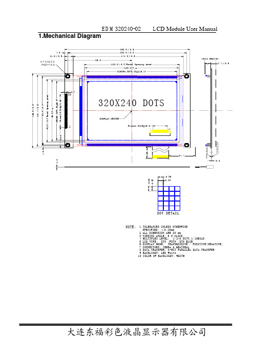
EDM320240-02 L CD Module User Manual1.Mechanical Diagram9 BACKLIGHT: LED WhiteNOTE:1 TOLERANCES UNLESS OTHERWISE SPECIFIED: ±0.25mm2 ALL DIMENSION ARE IN mm3 VIESING ANGLE: 6 O'CLOCK4 MULTIPLEX LEVEL: 1/240 DUTY,1/16BIAS5 LCD TYPE: STN /FSTN /STN BLUE6 DISPLAY MODE: TRANSMISSIVE / POSITIVE(NEGATIVE)7 CONNECTORS: ZEBRA & HEATSEAL8 DATA TRANSFER: 8-BIT PARALLEL DATA TRANSFER 10 COLOR OF BACKLIGHT: WHITEE D M320240-02L C D M o d u l e U s e r M a n u a l2.ScopeThis manual defines general provisions as well as inspection standards for standardLCD module. If the event of unforeseen problem or unspecified items may occur, pleasecontact the nearest supplier or our company.3.WarrantyIf module is not stored or used as specified in this manual, it will be void the 12-month warranty.4.Features4-1. Features(1) Display mode: Transmissive/positiveFSTN LCD(2) Display color: Display dots: WhiteBackground : Black(3)Display Format: 320(w)×240(h) full dots(4)Input data: 8-bit parallel data interfaced from a MPU(5) Multiplex ratio: 1/240 Duty, 1/16Bias(6)Viewing direction: 6 O’clock(7) Back light : White LED(8) Controller: SED1335/RA8835AP34-2. Mechanical featuresItem SpecificationsUnit Outline dimensions 160.0(W)×109.0(H) ×12.0Max.(T) mm Viewing Area 120.0(W)×90.0(H) mmImage Area 115.17(W)×86.37(H) mmNumber of Dots 320 (W)×240(H) --- Dot Size 0.33(W)×0.33(H) mmDot Pitch 0.36(W)×0.36(H) mmWeight --- g 4-3.Absolute maximum ratingsUnitsMaxCondition MinItem SymbolPower supply for logic Vdd-Vss 25℃ -0.3 7.0 VOperating voltage for LCD Vdd-V0 25℃ -0.3 28.0 VVdd+0.3 V Input voltage Vin 25℃ -0.3Operating temperature Top --- ﹣20 70℃Storage temperature Tstg --- ﹣25 80℃E D M 320240-02 L C D M o d u l e U s e r M a n u a lNote:1) The modules may be destroyed if they are used beyond absolute maximum ratings.In ordinary operation, it is desirable to use them within recommended operation conditions. Using the modules beyond these conditions may cause malfunction and poor reliability.2) All voltage values are referenced to GND=0V. 4-4Electrical CharacteristicsItem Symbol Conditions Min. Typ. Max. UnitSupply VoltageVdd — 4.5 5.0 5.5Register data retention voltage Voh—2.0 ---- 6.0VInput leakage currentILI VI=Vdd --- 0.05 2.0Output leakage current ILo VI=Vdd --- 0.10 5.0 uAQuiescent supply current IQ Sleep mode Vosc1=V/cs=V/rd=Vdd --- 0.05 20.0 uA Oscillator frequency Fosc 1.0 --- 10.0 MHz External clock frequency Fcl 1.0----10.0MHzOscillator feedback resistance RfMeasured at crystal 47.5% duty cycle0.5 1.0 3.0 M ΩTTL“H” Level Vih Note 1 0.5Vdd — Vdd Input Voltage “L” Level Vil Note 1Vss — 0.2Vdd “H” Level Vih IOH=-5.0mA, Note 1 2.4 — — Output Voltage “L” LevelVilIOL=5.0mA, Note 1——Vss+0.4VCOMS “H” Level Vih Note 2 0.8Vdd — Vdd Input Voltage “L” Level Vil Note 2Vss — 0.2Vdd “H” Level Vih IOH=-2.0mA, Note 2Vdd-0.4— — Output Voltage“L” LevelVilIOL=1.6mA ,Note 2——Vss+0.4VNote: <1>D0 to D7,A0,/CS,/RD,/WR,VD0 to VD7,VA0 toVA15,/VRD,/VWRand/vce arettl-level inputs<2>SEL1 and NT/PL are CMOS-level inputs.YD,XD0toXD3,XSCL,XECL,LP ,WF, YSCL,YDIS and CLO are CMOS-level outputs.4-5 Electro-optical CharacteristicsItem Symbol Conditions Min. Typ. Max. Unit-20℃ --- --- ---25℃ --- 28.0 --- LCD Driving Voltage (Recommended voltage)Vop70℃ --- --- ---V Currentconsumption(No B/L)logic IddVdd=5VFflm=75Hz—20 ---- mAPower supply for logic Vdd-Vss 25℃ 2.7 — 5.5 V4-6 LED back light specificationsE D M320240-02L C D M o d u l e U s e r M a n u a lStandard ValuesItemUnit Min. Typ. Max.ConditionSupply Voltage V — 4.1 --- —Current mA---100------ Luminous Color — W hite ---Operating Temp. ℃-20 ~ +70 —Storage Temp. ℃-30 ~ +80 —5.I/O Terminal5-1I/O ConnectionPin No. Symbol Function1 Vss Power supply (GND)2 Vdd Power supply (+)3 V0 Noconnection4 A0Register select signalA0=1, Instruction register ,A0=0, Data register5 /WR 8080: Write signal; 6800: W/R signal6 /RD 8080: Read signal; 6800: Enable signal7-14 DB0-DB7 Data bus line15 /CS Chip select16 /RES Controller reset signal17 VEE No connection18 SEL1 H:6800; L:808019 FG Frame ground20 NC Noconnection 5-2 Signal timing diagram5-2-1 8080 family interface Timing。
西门子SINAMICS S120驱动系统书面规格表单单机模块说明书

9/47Siemens NC 61 · 2007/20089■OverviewA wide range of single-axis and two-axis Motor Modules with graded current/power ratings can be supplied:•Single Motor Modules: Single-axis variantBooksize format with rated output currents of 3A to 200 A •Double Motor Modules: Two-axis variantBooksize format with rated output currents of 3A to 18 A In principle, all Single Motor and Double Motor Modules can be operated on Smart Line Modules or Active Line Modules for the corresponding voltage range.■DesignThe Single Motor Modules in booksize format feature the following interfaces as standard:•2 DC link connections via integrated DC link busbars •1 electronics power supply connection via integrated 24V DC busbars•3 DRIVE-CLiQ sockets•1 motor connection, plug-in (not included in scope of supply) or screw-stud depending on rated output current •1 safe standstill input (enable pulses)•1 safe motor brake control•1 temperature sensor input (KTY84-130 or PTC)•2 PE (protective earth) connectionsThe status of the Motor Modules is indicated via two multi-color LEDs.The motor cable shield is inside the connector on 50 mm (1.97 in) and 100 mm (3.94 in) width modules. A shield connection kit can be supplied for 150 mm, 200 mm and300 mm (5.91 in, 7.87 in and 11.81 in) wide modules. On these modules, the motor cable shield can be connected using a tube clip.The signal cable shield can be connected to the Motor Module by means of a shield connection terminal, e.g. Weidmüller type KLBÜ3-8SC.■Design (continued)The scope of supply of the Motor Modules includes:•DRIVE-CLiQ cable (length depends on module width) to connect Motor Module to adjacent module•Jumper for connecting the 24V DC busbar to the adjacent Motor Module •Connector X21•Connector X11 for the motor brake connection (for Motor Modules with a rated output current of 45A to 200A)•2 blanking plugs for sealing unused DRIVE-CLiQ sockets•Fan insert for the 132 A and 200 A Motor Modules (the voltage for the fan insert is supplied by the Motor Module)•1 set of warning signs in foreign languages■IntegrationSingle Motor Modules communicate with a CU320 Control Unit or SINUMERIK solution line via DRIVE-CLiQ.■Technical specifications1)Note correlation between max. output frequency, pulse frequencyand current derating; see system description on the CD-ROMsupplied with the catalog for further information.General technical specificationsSiemens NC 61 · 2007/20089■Technical specifications (continued)1)Rated DC link current for dimensioning an external DC connection. For DC link current calculation for dimensioning the Line Module,see system description "Power units/Line Modules" on the CD-ROM supplied with the catalog.2)Power loss of Motor Module at rated power without losses of 24 V DC electronics power supply.3)Not included in scope of supply, see Accessories.DC link voltage 510 ... 720 V DC Order No.•Internal air cooling 6SL3120-1TE13-0AA36SL3120-1TE15-0AA36SL3120-1TE21-0AA36SL3120-1TE21-8AA36SL3120-1TE23-0AA3•External air cooling 6SL3121-1TE13-0AA36SL3121-1TE15-0AA36SL3121-1TE21-0AA36SL3121-1TE21-8AA36SL3121-1TE23-0AA3Product name Single Motor Modules in booksize format Output current•Rated current I rated A 3591830•Base load current I H A 2.6 4.37.715.325.5•for S6 duty (40%)I S6A 3.56102440•I max , maximumA610183656Power•with 600 V DC link voltage kW (HP)1.6 (1.5) 2.7 (3) 4.8 (5)9.7 (10)16.0 (20)•based on I H kW (HP)1.4 (1) 2.3 (2.5) 4.1 (5)8.2 (10)13.7 (18)Rated pulse frequency kHz 44444DC link current I d 1)A 3.66112236Current capacity •24 V DC busbarsA2020202020If, due to a number of Line and Motor Modules being mounted side-by-side, the current carrying capacity exceeds 20 A, an additional 24V DC connection using a 24V terminal adapter is required (connection cross-section, max. 6mm 2, fuse protection, max. 20 A).•DC link busbars A 100100100100100DC link capacitance μF 110110*********Current requirement with 24 V DC, max.A0.850.850.850.850.9Power loss•Internal air cooling kW0.0350.0550.0800.1650.290•External air cooling int./ext.2)kW 0.015/0.0150.023/0.030.035/0.0450.075/0.090.08/0.210Cooling air requirement m 3/s (ft 3/s)0.008(0.283)0.008(0.283)0.008(0.283)0.008(0.283)0.016(0.565)Sound pressure level dB (A)<60<60<60<60<60Motor connection U2, V2, W2Plug-in connector (X1)3), max. 30A Shield connection Integrated in connector (X1)PE connectionOn housing with M5 screwMotor brake connection Integrated into the plug-in motor connector (X1), 24 V DC, 2 AMotor cable length, max.•Shielded m (ft)50 (164)50 (164)50 (164)70 (230)70 (230)•Unshielded m (ft)75 (246)75 (246)75 (246)100 (328)100 (328)Degree of protection IP20IP20IP20IP20IP20Dimensions •Width mm (in)50 (1.97)50 (1.97)50 (1.97)50 (1.97)100 (3.94)•Height mm (in)380 (14.98)380 (14.98)380 (14.98)380 (14.98)380 (14.98)•Depth-with internal air cooling mm (in)270 (10.63)270 (10.63)270 (10.63)270 (10.63)270 (10.63)-with external air cooling in front of/behind mounting surface mm (in)226/66.5 (8.9/2.6)226/66.5 (8.9/2.6)226/66.5 (8.9/2.6)226/66.5 (8.9/2.6)226/66.5 (8.9/2.6)Weight, approx.•with internal air cooling kg (lb) 5.0 (11) 5.0 (11) 5.0 (11) 5.0 (11) 6.9 (15)•with external air coolingkg (lb) 5.7 (13) 5.7 (13) 5.7 (13) 5.7 (13)8.5 (19)Siemens NC 61 · 2007/20089■Technical specifications (continued)1)Rated DC link current for dimensioning an external DC connection.For DC link current calculation for dimensioning the Line Module, see system description "Power units/Line Modules" on the CD-ROM supplied with the catalog.2)Power loss of Motor Module at rated power without losses of 24 V DC electronics power supply.3)The fan is supplied with the Motor Module and must be installed before the Motor Module is commissioned.DC link voltage 510 ... 720 V DC Ordering data •Internal air cooling 6SL3120-1TE24-5AA36SL3120-1TE26-0AA36SL3120-1TE28-5AA36SL3120-1TE31-3AA36SL3120-1TE32-0AA3•External air cooling 6SL3121-1TE24-5AA36SL3121-1TE26-0AA36SL3121-1TE28-5AA36SL3121-1TE31-3AA36SL3121-1TE32-0AA3Product name Single Motor Modules in booksize format Output current•Rated current I rated A 456085132200•Base load current I H A 385168105141•for S6 duty (40%)I S6A 6080110150250•I max , maximumA85113141210282Power•with 600 V DC link voltage kW (HP)24 (30)32 (40)46 (60)71 (100)107 (150)•based on I H kW (HP)21 (25)28 (40)37 (50)57 (75)76 (100)Rated pulse frequency kHz 44444DC link current I d 1)A 5472102158200Current capacity •24 V DC busbarsA2020202020If, due to a number of Line and Motor Modules being mounted side-by-side, the current carrying capacity exceeds 20 A, an additional 24V DC connection using a 24V terminal adapter is required (connection cross-section, max. 6mm 2, fuse protection, max. 20 A).•DC link busbars A 200200200200200DC link capacitance μF 11751410188028203995Current requirement with 24 V DC, max.A1.21.21.51.51.5Power loss•Internal air cooling in control cabinetkW 0.430.590.75 1.25 2.05•External air cooling int./ext.2)kW 0.011/0.320.135/0.4550.16/0.590.25/1.00.4/1.65Cooling air requirement m 3/s(ft 3/s)0.031(1.095)0.031(1.095)0.044(1.554)0.144(5.085)0.144(5.085)Sound pressure leveldB (A)<65<65<60<73<73Motor connection U2, V2, W2M6 screw studs, (X1)M6 screw studs, (X1)M8 screw studs, (X1)M8 screw studs, (X1)M8 screw studs, (X1)•Conductor cross-section mm 2 2.5...50 2.5...50 2.5...95, 2×35 2.5...120, 2×50 2.5...120, 2×50Shield connection See Accessories See Accessories See Accessories See Accessories See Accessories PE connectionOn housing with M6 screwOn housing with M6 screwOn housing with M6 screwOn housing with M8 screwOn housing with M8 screwMotor brake connection Plug-in connector (X11), 24 V DC, 2 A Plug-in connector (X11), 24 V DC, 2 A Plug-in connector (X11), 24 V DC, 2 A Plug-in connector (X11), 24 V DC, 2 A Plug-in connector (X11), 24 V DC, 2 A Motor cable length, max.•Shielded m (ft)100 (328)100 (328)100 (328)100 (328)100 (328)•Unshielded m (ft)150 (492)150 (492)150 (492)150 (492)150 (492)Degree of protection IP20IP20IP20IP20IP20Dimensions •Width mm (in)150 (5.91)150 (5.91)200 (7.87)300 (11.81)300 (11.81)•Heightmm (in)380 (14.96)380 (14.96)380 (14.96)380, (14.96)with fan 3): 629 (24.8)380, (14.96)with fan 3): 629 (24.8)•Depth-with internal air cooling mm (in)270 (10.63)270 (10.63)270 (10.63)270 (10.63)270 (10.63)-with external air cooling in front of/behind mounting surface mm (in)226/71 (8.9/2.8)226/71 (8.9/2.8)226/92 (8.9/3.6)226/82 (8.9/3.2)226/82 (8.9/3.2)Weight, approx.•with internal air cooling kg (lb)9 (20)9 (20)15 (33)21 (46)21 (46)•with external air coolingkg (lb)13.2 (29)13.4 (30)17.2 (38)27.2 (60)30 (66)9■Selection and Ordering Data■Accessories (continued)9/50Siemens NC 61 · 2007/20089/51Siemens NC 61 · 2007/20089■Characteristic curvesOverload capabilityDuty cycle with previous load Duty cycle without previous load S6 duty cycle with previous load with a duty cycle duration of 600 s S6 duty cycle with previous load with a duty cycle duration of 60 sDuty cycle with 60 s overload with a duty cycle duration of 300 sDuty cycle with 30 s overload with a duty cycle duration of 300 s9■Characteristic curves (continued)Derating characteristicsOutput current dependent on pulse frequencyOutput current dependent on ambient temperatureOutput current dependent on installation altitudeVoltage derating dependent on pulse frequency9/52Siemens NC 61 · 2007/2008。
Modicon M340自动化平台BMXP341000处理器模块说明书

DEL-BMXP341000i s c l a im e r : T h i s d o c u m e n t a t i o n i s n o t i n t e n d e d a s a s u b s t i t u t e f o r a n d i s n o t t o b e u s e d f o r d e t e r m i n i n g s u i t a b i l i t y o r r e l i a b i l i t y o f t h e s e p r o d u c t s f o r s p e c i f i c u s e r a p p l i c a t i o n sProduct datasheetCharacteristicsBMXP341000processor module M340 - max 512 discrete + 128analog I/O - ModbusMainRange of productModicon M340 automation platform Product or component type Processor module Number of racks 2Number of slots11Discrete I/O processor capacity 512 I/O single-rack configuration Analogue I/O processor capacity 128 I/O multi-rack configuration 66 I/O single-rack configuration Number of application specific channel 20MonitoringDiagnostic counters Modbus Event counters ModbusComplementaryControl channelsProgrammable loopsIntegrated connection typeUSB port 12 Mbit/sNon isolated serial link RJ45 character mode asynchronous in baseband RS232C full duplex 0.3...19.2 kbit/s 2 twisted shielded pairsNon isolated serial link RJ45 character mode asynchronous in baseband RS485 half duplex 0.3...19.2 kbit/s 1 twisted shielded pairNon isolated serial link RJ45 Modbus master/slave RTU/ASCII asynchronous in baseband RS232C half duplex 0.3...19.2 kbit/s 1 twisted shielded pairNon isolated serial link RJ45 Modbus master/slave RTU/ASCII asynchronous in baseband RS485half duplex 0.3...19.2 kbit/s 1 twisted shielded pair Communication module processor 2 Ethernet communication module 2 AS-Interface module Number of devices per segment 0...32 character mode 0...32 ModbusNumber of devices 2 point-to-point character mode 2 point-to-point ModbusBus length0...10 m serial link non isolated character mode segment 0...10 m serial link non isolated Modbus segment0...1000 m serial link isolated character mode segment 0...1000 m serial link isolated Modbus segment 0...15 m character mode point-to-point0...15 m Modbus point-to-pointTap links length0...15 m serial link non isolated character mode segment0...15 m serial link non isolated Modbus segment0...40 m serial link isolated character mode segment0...40 m serial link isolated Modbus segmentNumber of addresses0...248 character mode0...248 ModbusRequests 1 K data bytes per request character mode252 data bytes per RTU request Modbus504 data bytes per ASCII request ModbusControl parameter One CRC on each frame (RTU) ModbusOne LRC on each frame (ASCII) character modeOne LRC on each frame (ASCII) ModbusMemory description2048 kB internal RAM128 kB internal RAM for data1792 kB internal RAM for program constants and symbolsSupplied memory card (BMXRMS008MP) for backup of programs, constants, symbols and data Maximum size of object areas128 kB unlocated internal data16250 %Mi located internal bits32464 %MWi internal words located internal data32760 %KWi constant words located internal dataDefault size of object areas128 %KWi constant words located internal data256 %Mi located internal bits512 %MWi internal words located internal dataApplication structure 1 periodic fast task1 cyclic/periodic master taskNo auxiliary task32 event tasksExecution time per instruction0.18 µs Boolean0.26 µs double-length words0.38 µs single-length words1.74 µs floating pointsNumber of instructions per ms 4.2 Kinst/ms 65 % Boolean + 35 % fixed arithmetic5.4 Kinst/ms 100 % BooleanSystem overhead0.2 ms fast task1.05 ms master taskCurrent consumption72 mA 24 V DCSupply Internal power supply via rackMarking CEStatus LED 1 LED green processor running (RUN)1 LED red I/O module fault (I/O)1 LED red memory card fault (CARD ERR)1 LED red processor or system fault (ERR)1 LED yellow activity on Modbus (SER COM)Product weight0.2 kgEnvironmentAmbient air temperature for operation0...60 °CRelative humidity10...95 % without condensationIP degree of protection IP20Protective treatment TCStandards UL 508IEC 61131-2EN 61131-2CSA C22.2 No 213 Class I Division 2CSA C22.2 No 142Offer SustainabilitySustainable offer status Green Premium productRoHS (date code: YYWW)Compliant - since 0722 - Schneider Electric declaration of conformitySchneider Electric declaration of conformityREACh Reference contains SVHC above the threshold - Go to CaP for more detailsGo to CaP for more detailsProduct environmental profile AvailableProduct environmental Product end of life instructionsAvailableEnd of life manualContractual warrantyWarranty period18 monthsProduct datasheetDimensions DrawingsBMXP341000Modules Mounted on RacksDimensions(1)With removable terminal block (cage, screw or spring).(2)With FCN connector.DEL-BMXP341000。
NHD-320240WX-COTFH-V#I040,NHD-320240WX-C0TFH-V#I040, 规格书,Datasheet 资料

User’s GuideNHD-320240WX-COTFH-V#I040 LCM(Liquid Crystal Display Graphic Module)RoHS CompliantNHD-320240-WX-C O- T-F-H-V#-I040-Newhaven Display320 x 240 DotsW= V ersion Line X=Display Type- Tab TypeModel/ Serial NumberWhite LED B/LFS TN(+)Transflective, 6:00 View,Wide Temperature (-20 ~ +70c)W ith Built in Positive Voltage, #: RoHS CompliantI: ICIST3031TA0# ICIST3032TA0#; 04Sales code 0: Version SGX320240CEV#002For product support, contactNewhaven Display International2511 Technology Drive, #101Elgin, IL 60124Tel: (847) 844-8795 Fax: (847) 844-8796February18, 2009RECORDS OF REVISIONDOC. FIRST ISSUEVER S ION DATEREVISEDPAGE NO.SUMMARYA 2008.5.13 Modify Contour Drawing2008/3/12First issueContents1.Module classification information2.Precautions in Use of LCM3.General Specification4.Absolute Maximum Ratings5.Electrical Characteristics6.Optical Characteristics7.Power Supply for LCD Module8.Contour Drawing & Block Diagram9.Interface Pin Function10.Timing Characteristics11.Reliability12. Backlight Information13. Inspection specification14. Material List of Components for RoHs3 1.Module Classification InformationġġNHD 320240 WġX 炼C0 T F H – V#I040ġġc d e f g h i j9c Brand烉Newhaven Displayd Display Font烉320 * 240 Dotse Factory Line: Wf Display Type烉HɦCharacter Type, GɦGraphic Type, Cɦ Color, XɦTab Typeg Model / Serial number: C0 Æ With RA8835 Controllerh Backlight Type烉NɦWithout backlightBɦEL, Blue greenDɦEL, GreenWɦEL, WhiteFɦCCFL, WhiteYɦLED, Yellow Green TɦWhite LED AɦLED, Amber RɦLED, RedOɦLED, Orange GɦLED, Greeni LCD Mode烉BɦTN Positive, GrayNɦTN Negative,GɦSTN Positive, Gray TɦFSTN NegativeYɦSTN Positive, Yellow Green MɦSTN Negative, BlueFɦFSTN Positivej LCD Polarize Type/Temperature range/View direction AɦReflective, N.T, 6:00DɦReflective, N.T, 12:00GɦReflective, W. T, 6:00JɦReflective, W. T, 12:00BɦTransflective, N.T,6:00EɦTransflective, N.T.12:00HɦTransflective, W.T,6:00KɦTransflective, W.T,12:00CɦTransmissive, N.T,6:00FɦTransmissive, N.T,12:00IɦTransmissive, W. T, 6:00LɦTransmissive, W.T,12:009 Special Code #: RoHS ; V: Built in Positive Voltage ;I: ICIST3031TA0# ICIST3032TA004: Sales Code 0: VersionSGX320240CEV#0022.Precautions in Use of LCD Module(1)Avoid applying excessive shocks to the module or making any alterations or modifications to it. (2)Don’t make extra holes on the printed circuit board, modify its shape or change the components of LCD Module.(3)Don’t disassemble the LCM.(4)Don’t operate it above the absolute maximum rating. (5)Don’t drop, bend or twist LCM. (6)Soldering: only to the I/O terminals.(7)Storage: please storage in anti-static electricity container and clean environment. (8)Winstar have the right to change the passive components (9)Winstar have the right to change the PCB Rev.3.General SpecificationITEM S TANDARD VALUE UNIT Number of dots 320x240dots Outline dimension94.7(W)x 71.7(H)x 8.6max(T)mm View area 81.4(W) x 61.0(H) mm Active area 76.78(W)x 57.58(H) mm Dot size 0.225(W)x 0.225(H) mm Dot pitch 0.24(W)x 0.24(H)mmLCD type FS TN Positive Transflective,View direction6 o’clockBacklight LED, White4.Absolute Maximum RatingsITEM SYMBOL MIN.TYP. MAX. UNIT Operating Temperature T OP -20Ё+70 к Storage Temperature T ST -30 Ё +80кInput VoltageV I 0 Ё V DD V Supply Voltage For Logic V DD 0 Ё 3.5 V Supply Voltage For LCD Vo-V SS 0 Ё 30 V DC-DC converter outputVEE235.Electrical CharacteristicsITEM SYMBOL CONDITIONMIN. TYP. MAX. UNIT Logic VoltageV DD -V SSЁ 3.0 3.3 3.6 V S upply Voltage ForLCDVo-V SS Ta= -20кTa=25к Ta=+70к Ё Ё 12.2 Ё 18.7 Ё 22.5 Ё ЁV V VInput High Volt. V IH Ё 0.5V DD Ё V DD V Input Low Volt. V IL Ё V SS Ё 0.2V DD V Output High Volt. V OH Ё 2.4 Ё ЁVOutput Low Volt. V OL Ё ЁЁ0.4 VSupply CurrentI DDЁ20.0 30.0 50.0mA6.Optical CharacteristicsITEM YMBAL CONDITIONMIN TYP MAX UNIT (V)Ӱ CR Њ230 Ё 60 deg. View Angle (H)ӽ CR Њ2 -45 Ё 45 deg. Contrast Ratio CR Ё Ё 5ЁЁT rise Ё Ё 200 300 ms Response TimeT fallЁЁ150 200 ms6.1ʳDefinitionsϮView Angles ʳʳʳʳʳʳʳʳʳʳʳʳʳʳϮContrast RatioʳϮResponse time7.Power Supply for LCD Module8.Contour Drawing & Block diagramDETAILDOTS SIZE ResetPower ON CL1M *:6800 family or 8080family interface selectable.*CS RA8835Controller32K SRAM CL2DB0~DB3FLMFGNDFrame PADN.V.GeneratorMPUDriverSeg241~320Seg161~240Driver Seg81~160Driver Com161~240Com81~160DriverDriver DB0~DB7A0WR RD P o w e r C i r c u i tB i a s a n d Com1~80Driver RESInternal contrast adjustment.Seg1~80Driver 320X240 DOTVoVR Vdd 20KVss9.Interface Pin Function10. Timing CharacteristicsPLEASE TO CONSUL RA8835 SPEC11.RELIABILITYContent of Reliability Test (wide temperature, -20к~70к)Note1: No dew condensation to be observed.Note2: The function test shall be conducted after 4 hours storage at the normal Temperature and humidity after remove from the test chamber.Note3: Vibration test will be conducted to the product itself without putting it in a container.12. Backlight InformationSpecificationPARAMETER SYMBOL MIN TYP MAX UNIT TEST ʳCONDITION Supply Current ILED 100 120 180 mA V=3.5VSupply Voltage V 3.4 3.5 3.6VReverse Voltage VRЁЁ5 VLuminous Intensity IV 160 200ЁCD/M2 ILED=120mA Life TimeЁ50KЁHr. ILED Љ120mAColor whiteNote: The LED of B/L is drive by current only, drive voltage is for reference only. drive voltage can make driving current under safety area (current between minimum and maximum)B/LKA RR LCMpin19pin20Drive from pin19,pin2013. Inspection specificationNO Item Criterion AQL01Electrical Testing1.1 Missing vertical, horizontal segment, segment contrast defect. 1.2 Missing character , dot or icon. 1.3 Display malfunction.1.4 No function or no display.1.5 Current consumption exceeds product specifications.1.6 LCD viewing angle defect. 1.7 Mixed product types. 1.8 Contrast defect.0.65 02 Black or white spots onLCD (display only)2.1 White and black spots on display Љ0.25mm, no more than three white or black spots present.2.2 Densely spaced: No more than two spots or lines within 3mm2.53.1 Round type : As following drawingӥːʻʳ̋ʳʾʳ̌ʳʼʳ˂ʳ˅ʳʳʳʳʳ˦˜˭˘ʳ˔˶˶˸̃̇˴˵˿˸ʳˤʳ˧ˬʳʳʳʳʳʳӥЉ˃ˁ˄˃˔˶˶˸̃̇ʳ́̂ʳ˷˸́̆˸ʳ˃ˁ˄˃ІӥЉ˃ˁ˅˃˅ʳ˃ˁ˅˃ІӥЉ˃ˁ˅ˈ˄ʳ˃ˁ˅ˈІӥʳ˃ʳ 2.503LCD blackspots, white spots, contaminati on (non-display)3.2 Line type : (As following drawing)Length Width Acceptable Q TY--- W Љ˃ˁ˃˅ Accept no dense L Љˆˁ˃0.02ІW Љ˃ˁ˃ˆL Љ˅ˁˈ0.03ІW Љ˃ˁ˃ˈʳ2 --- 0.05ІW As round type2.504Polarizer bubblesIf bubbles are visible, judge using black spot specifications, not easy to find, must check inspecify direction.Size ӥ Acceptable Q TY ӥЉ˃ˁ˅˃Accept no dense ˃ˁ˅˃ІӥЉ˃ˁˈ˃ 3 ˃ˁˈ˃ІӥЉ˄ˁ˃˃2 ˄ˁ˃˃Іӥ 0 Total Q TY 32.5NO Item CriterionAQL 05 Scratches Follow NO.3 LCD black spots, white spots, contamination06Chipped glassSymbols Define: x: Chip length y: Chip width z: Chip thickness k: S eal width t: Glass thickness a: LCD side length L: Electrode pad length:6.1 General glass chip :6.1.1 Chip on panel surface and crack between panels:̍ˍʳ˖˻˼̃ʳ̇˻˼˶˾́˸̆̆ʳ̌ˍʳ˖˻˼̃ʳ̊˼˷̇˻ʳ̋ˍʳ˖˻˼̃ʳ˿˸́˺̇˻ʳ˭Љ˄˂˅̇ʳˡ̂̇ʳ̂̉˸̅ʳ̉˼˸̊˼́˺ʳ˴̅˸˴̋Љ˄˂ˋ˴ʳ˄˂˅̇І̍Љ˅̇ʳˡ̂̇ʳ˸̋˶˸˸˷ʳ˄˂ˆ˾ʳʳ̋Љ˄˂ˋ˴ʳФ˜˹ʳ̇˻˸̅˸ʳ˴̅˸ʳ˅ʳ̂̅ʳ̀̂̅˸ʳ˶˻˼̃̆ʿʳ̋ʳ˼̆ʳ̇̂̇˴˿ʳ˿˸́˺̇˻ʳ̂˹ʳ˸˴˶˻ʳ˶˻˼̃ˁʳʳˉˁ˄ˁ˅ʳ˖̂̅́˸̅ʳ˶̅˴˶˾ˍʳʳʳ̍ˍʳ˖˻˼̃ʳ̇˻˼˶˾́˸̆̆ʳ̌ˍʳ˖˻˼̃ʳ̊˼˷̇˻ʳ̋ˍʳ˖˻˼̃ʳ˿˸́˺̇˻ʳ˭Љ˄˂˅̇ʳˡ̂̇ʳ̂̉˸̅ʳ̉˼˸̊˼́˺ʳ˴̅˸˴̋Љ˄˂ˋ˴ʳ˄˂˅̇І̍Љ˅̇ʳˡ̂̇ʳ˸̋˶˸˸˷ʳ˄˂ˆ˾ʳʳ̋Љ˄˂ˋ˴ʳФ˜˹ʳ̇˻˸̅˸ʳ˴̅˸ʳ˅ʳ̂̅ʳ̀̂̅˸ʳ˶˻˼̃̆ʿʳ̋ʳ˼̆ʳ̇˻˸ʳ̇̂̇˴˿ʳ˿˸́˺̇˻ʳ̂˹ʳ˸˴˶˻ʳ˶˻˼̃ˁʳʳ2.5NO ItemCriterionAQL06 Glass crack ˦̌̀˵̂˿̆ʳˍʳx: Chip length y: Chip width z: Chip thickness k: S eal width t: Glass thickness a: LCD side length L: Electrode pad length6.2 Protrusion over terminal : 6.2.1 Chip on electrode pad :̌ˍʳ˖˻˼̃ʳ̊˼˷̇˻ʳʳ̋ˍʳ˖˻˼̃ʳ˿˸́˺̇˻ʳ̍ˍʳ˖˻˼̃ʳ̇˻˼˶˾́˸̆̆ʳ̌Љ˃ˁˈ̀̀ʳ̋Љ˄˂ˋ˴ʳ˃ʳІʳ̍ʳЉʳ̇ʳˉˁ˅ˁ˅ʳˡ̂́ˀ˶̂́˷̈˶̇˼̉˸ʳ̃̂̅̇˼̂́ˍʳʳ̌ˍʳ˖˻˼̃ʳ̊˼˷̇˻ʳʳ̋ˍʳ˖˻˼̃ʳ˿˸́˺̇˻ʳ̍ˍʳ˖˻˼̃ʳ̇˻˼˶˾́˸̆̆ʳ̌Љʳ˟ʳ̋Љ˄˂ˋ˴ʳ˃ʳІʳ̍ʳЉʳ̇ʳФ˜˹ʳ̇˻˸ʳ˶˻˼̃̃˸˷ʳ˴̅˸˴ʳ̇̂̈˶˻˸̆ʳ̇˻˸ʳ˜˧ˢʳ̇˸̅̀˼́˴˿ʿʳ̂̉˸̅ʳ˅˂ˆʳ̂˹ʳ̇˻˸ʳ˜˧ˢʳ̀̈̆̇ʳ̅˸̀˴˼́ʳ˴́˷ʳ˵˸ʳ˼́̆̃˸˶̇˸˷ʳ˴˶˶̂̅˷˼́˺ʳ̇̂ʳ˸˿˸˶̇̅̂˷˸ʳ̇˸̅̀˼́˴˿ʳ̆̃˸˶˼˹˼˶˴̇˼̂́̆ˁʳФ˜˹ʳ̇˻˸ʳ̃̅̂˷̈˶̇ʳ̊˼˿˿ʳ˵˸ʳ˻˸˴̇ʳ̆˸˴˿˸˷ʳ˵̌ʳ̇˻˸ʳ˶̈̆̇̂̀˸̅ʿʳ̇˻˸ʳ˴˿˼˺́̀˸́̇ʳ̀˴̅˾ʳ́̂̇ʳ˵˸ʳ˷˴̀˴˺˸˷ˁʳˉˁ˅ˁˆʳ˦̈˵̆̇̅˴̇˸ʳ̃̅̂̇̈˵˸̅˴́˶˸ʳ˴́˷ʳ˼́̇˸̅́˴˿ʳ˶̅˴˶˾ˁʳʳʳ̌ˍʳ̊˼˷̇˻ʳʳ̋ˍʳ˿˸́˺̇˻ʳ̌Љ˄˂ˆ˟ʳ̋ʳЉʳ˴ʳ2.5NO ItemCriterionAQLNO Item Criterion AQL12Generalappearanceʳ˄˅ˁ˄ʳˡ̂ʳ̂̋˼˷˴̇˼̂́ʿʳ˶̂́̇˴̀˼́˴̇˼̂́ʿʳ˶̈̅̉˸̆ʳ̂̅ʿʳ˵˸́˷̆ʳ̂́ʳ˼́̇˸̅˹˴˶˸ʳˣ˼́ʳʻˢ˟˕ʼʳ̂˹ʳ˧˖ˣˁʳ˄˅ˁ˅ʳˡ̂ʳ˶̅˴˶˾̆ʳ̂́ʳ˼́̇˸̅˹˴˶˸ʳ̃˼́ʳʻˢ˟˕ʼʳ̂˹ʳ˧˖ˣˁʳ˄˅ˁˆʳˡ̂ʳ˶̂́̇˴̀˼́˴̇˼̂́ʿʳ̆̂˿˷˸̅ʳ̅˸̆˼˷̈˸ʳ̂̅ʳ̆̂˿˷˸̅ʳ˵˴˿˿̆ʳ̂́ʳ̃̅̂˷̈˶̇ˁʳ˄˅ˁˇʳ˧˻˸ʳ˜˖ʳ̂́ʳ̇˻˸ʳ˧˖ˣʳ̀˴̌ʳ́̂̇ʳ˵˸ʳ˷˴̀˴˺˸˷ʿʳ˶˼̅˶̈˼̇̆ˁʳ˄˅ˁˈʳ˧˻˸ʳ̈̃̃˸̅̀̂̆̇ʳ˸˷˺˸ʳ̂˹ʳ̇˻˸ʳ̃̅̂̇˸˶̇˼̉˸ʳ̆̇̅˼̃ʳ̂́ʳ̇˻˸ʳ˼́̇˸̅˹˴˶˸ʳ̃˼́ʳ̀̈̆̇ʳ˵˸ʳ̃̅˸̆˸́̇ʳ̂̅ʳ˿̂̂˾ʳ˴̆ʳ˼˹ʳ˼̇ʳ˶˴̈̆˸ʳ̇˻˸ʳ˼́̇˸̅˹˴˶˸ʳ̃˼́ʳ̇̂ʳ̆˸̉˸̅ˁʳ˄˅ˁˉʳ˧˻˸ʳ̅˸̆˼˷̈˴˿ʳ̅̂̆˼́ʳ̂̅ʳ̇˼́ʳ̂˼˿ʳ̂˹ʳ̆̂˿˷˸̅˼́˺ʳʻ˶̂̀̃̂́˸́̇ʳ̂̅ʳ˶˻˼̃ʳ˶̂̀̃̂́˸́̇ʼʳ˼̆ʳ́̂̇ʳ˵̈̅́˸˷ʳ˼́̇̂ʳ˵̅̂̊́ʳ̂̅ʳ˵˿˴˶˾ʳ˶̂˿̂̅ˁʳ˄˅ˁˊʳ˦˸˴˿˴́̇ʳ̂́ʳ̇̂̃ʳ̂˹ʳ̇˻˸ʳ˜˧ˢʳ˶˼̅˶̈˼̇ʳ˻˴̆ʳ́̂̇ʳ˻˴̅˷˸́˸˷ˁʳ˄˅ˁˋʳˣ˼́ʳ̇̌̃˸ʳ̀̈̆̇ʳ̀˴̇˶˻ʳ̇̌̃˸ʳ˼́ʳ̆̃˸˶˼˹˼˶˴̇˼̂́ʳ̆˻˸˸̇ˁʳ˄˅ˁˌʳ˟˖˗ʳ̃˼́ʳ˿̂̂̆˸ʳ̂̅ʳ̀˼̆̆˼́˺ʳ̃˼́̆ˁʳ˄˅ˁ˄˃ʳˣ̅̂˷̈˶̇ʳ̃˴˶˾˴˺˼́˺ʳ̀̈̆̇ʳ̇˻˸ʳ̆˴̀˸ʳ˴̆ʳ̆̃˸˶˼˹˼˸˷ʳ̂́ʳ̃˴˶˾˴˺˼́˺ʳ̆̃˸˶˼˹˼˶˴̇˼̂́ʳ̆˻˸˸̇ˁʳ˄˅ˁ˄˄ʳˣ̅̂˷̈˶̇ʳ˷˼̀˸́̆˼̂́ʳ˴́˷ʳ̆̇̅̈˶̇̈̅˸ʳ̀̈̆̇ʳ˶̂́˹̂̅̀ʳ̇̂ʳ̃̅̂˷̈˶̇ʳ̆̃˸˶˼˹˼˶˴̇˼̂́ʳ̆˻˸˸̇ˁʳʳ2.50.652.52.52.52.52.50.650.650.650.6514. Material List of Components for RoHs1. Newhaven Display International hereby declares that all of or part of products (with the mark “#”in code), including, but not limited to, the LCM, accessories or packages, manufactured and/or delivered to your company (including your subsidiaries and affiliated company) directly or indirectly by our company (including our subsidiaries or affiliated companies) do not intentionally contain any of the substances listed in all applicable EU directives and regulations, including the following substances.Exhibit AΚThe Harmful Material ListMaterial (Cd) (Pb) (Hg) (Cr6+) PBBs PBDEsLimited Value 100ppm1000ppm1000ppm1000ppm1000ppm1000ppmAbove limited value is set up according to RoHS.2.Process for RoHS requirementΚ(1) Use the Sn/Ag/Cu soldering surfaceΙthe surface of Pb-free solder is rougher than we used before.(2) Heat-resistance temp.ΚReflowΚ250,30 seconds Max.кΙConnector soldering wave or hand solderingΚ320, 10 seconds max.к(3) Temp. curve of reflow, max. Temp.Κ235±5кΙRecommended customer’s soldering temp. of connectorΚ280, 3 seconds.кNewhaven LCM Sample Estimate Feedback SheetModule NumberΚPage: 1 1ΕPanel SpecificationΚ1.Panel TypeΚϭ PassϭNG ,2. View DirectionΚϭ Pass ϭNG ,3. Numbers of DotsΚϭ Pass ϭNG ,4. View AreaΚϭ Pass ϭNG ,5. Active AreaΚϭ Pass ϭNG ,6. Operating TemperatureΚϭ Pass ϭNG ,7. Storage TemperatureΚϭ Pass ϭNG ,8. OthersΚ2ΕMechanical SpecificationΚ1.PCB SizeΚϭ PassϭNG ,2. Frame SizeΚϭ Pass ϭNG ,3. Materal of FrameΚϭ Pass ϭNG ,4. Connector PositionΚϭ Pass ϭNG ,5. Fix Hole PositionΚϭ Pass ϭNG ,6. Backlight PositionΚϭ Pass ϭNG ,7. Thickness of PCBΚϭ Pass ϭNG ,8. Height of Frame to PCBΚϭ Pass ϭNG ,9. Height of ModuleΚϭ Pass ϭNG ,10. OthersΚϭ Pass ϭNG ,3ΕRelative Hole SizeΚ1. Pitch of ConnectorΚϭ Pass ϭNG ,2. Hole size of ConnectorΚϭ Pass ϭNG ,3. Mounting Hole sizeΚϭ Pass ϭNG ,4. Mounting Hole TypeΚϭ Pass ϭNG ,5. OthersΚϭ Pass ϭNG ,4ΕBacklight SpecificationΚ1.B/L TypeΚϭ PassϭNG ,2. B/L ColorΚϭ Pass ϭNG ,3. B/L Driving Voltage (Reference for LED Type)Κϭ Pass ϭNG ,4. B/L Driving CurrentΚϭ Pass ϭNG ,5. Brightness of B/LΚϭ Pass ϭNG ,6. B/L Solder MethodΚϭ Pass ϭNG ,7. OthersΚϭ Pass ϭNG ,ЇЇGo to page 2 ІІNewhavenModule NumberΚPage: 2Page 22 of 2210(A) 5ΕElectronic Characteristics of Module Κ1.Input Voltage Κϭ Passϭ NG , 2. Supply Current Κ ϭ Passϭ NG , 3. Driving Voltage for LCD Κ ϭ Passϭ NG , 4. Contrast for LCD Κ ϭ Passϭ NG , 5. B/L Driving Method Κ ϭ Passϭ NG , 6. Negative Voltage Output Κ ϭ Passϭ NG , 7. Interface Function Κ ϭ Passϭ NG , 8. LCD Uniformity Κ ϭ Passϭ NG , 9. ESD test Κ ϭ Passϭ NG , 10. Others Κϭ Pass ϭ NG , 6ΕSummary ΚSales signature ΚCustomer Signature Κ Date Κ / /芯天下--/。
320240液晶驱动 SED1335 控制器的液晶显示模块与单片机接口应用
320240液晶驱动SED1335 控制器的液晶显示模块与单片机接口应用2008年11月15日星期六20:161 引言液晶显示(Liquid Crystal Display)简称LCD,以其独特的低压、微功耗特性广泛应用于便携式电子产品如移动通信和笔记本电脑中。
Truly(信利)公司的点阵型液晶显示模块MSP-G320240DBCW 是一种内置SED1335控制器的大屏幕带背光液晶显示模块,SED1335是日本Seiko Epson公司生产的液晶显示控制器,是同类产品中功能较强的一款产品。
MSP-G320240DBCW模块以其优良的品质广泛应用于各类高级仪器仪表、POS机、彩屏手机、车载产品、军工产品等,本文以此模块为例,介绍SED1335的编程控制。
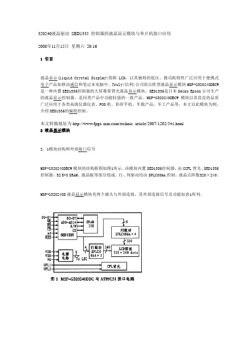
本文转载地址为/technic_article/2007/1202/541.html2 液晶显示模块2.1模块结构和外部接口信号MSP-G320240DBCW模块的结构框图如图1所示。
该模块内置SED1335控制器,由CCFL背光、SED1335控制器、32 K*8 SRAM、液晶板等部分组成。
行、列驱动均由SPLC086A控制,液晶点阵数320×240。
MSP-G320240D液晶显示模块有两个插头与外部连接,其外部连接信号及功能如表1所列。
从表1和图1可见,外部信号中除了电源外,其余控制信号都是用于控制SED1335控制器的。
其中包括数据线7位、地址线A0、片选信号及读写信号。
SED1335具有较强的I/O缓冲器,单片机访问SED1335不需要判断其是否为"忙"状态,SED1335可随时准备接收单片机的访问。
并及时地传输单片机发来的指令和数据。
另外,SED1335具有较强的管理显示存储器的性能,内置一个字符发生器,具有160种57点阵字体的字符,并能分区管理64 K 的显示存储器,可以同时管理3个或4个显示区,并能同时管理用户自定义字符发生器。