LPC1300 第11章 通用异步收发器
芯海科技 ARM M M0-based MCU 输出手册说明书

输出手册版本历史版本号说明日期1.0 初版2019-6-171.1 1. LRC频率:min(30->27),max(50->62)2. ADC特性更新: fADC-40℃≤ Trange ≤ 85℃,fADC≤14MHz,支持电压范围2.65≤ VDDA ≤5.5V;-40℃≤ Trange ≤ 105℃,fADC≤14MHz,支持电压范围2.7≤ VDDA ≤5.5V;-40℃≤ Trange ≤ 105℃,fADC≤12MHz,支持电压范围2.4≤ VDDA ≤5.5V;进入校准模式,fADC≤12MHz。
进入正常转换模式,fADC≤14MHz。
支持:-40℃≤ Trange ≤ 105℃和电压范围2.4≤ VDDA ≤5.5V;3. ADC特性更新:VDDA=2.4V时,Offset和ERR Gain更新2020-6-31.2 1.增加G6U6版本相关信息2020-6-191.3 1.更新温度传感器线性度参数,区分不同温度范围2020-8-262/56文件编号:CS-QR-YF-054A02目录输出手册版本历史 (2)目录 (3)1介绍 (5)2功能 (6)3器件一览 (8)4引脚描述 (10)4.1LQFP48 (10)4.2LQFP32 (10)4.3QFN28L (11)4.4TSSOP20 (11)4.5引脚描述 (12)5I/O 复用 (15)5.1PA口复用功能 (15)5.2PB口复用功能 (16)6存储器 (17)7功能描述 (21)7.1ARM®C ORTEX®-M0内核 (21)7.2存储器 (21)7.3时钟 (21)7.4工作环境 (23)7.4.1工作电压 (23)7.5启动模式 (23)7.6电源管理 (23)7.6.1低功耗模式 (23)7.6.2RTC和备用寄存器的电源电压VBAT (23)7.6.3上电复位/掉电复位(POR/PDR) (23)7.6.4低电压复位模块(LVD) (24)7.7通用输入输出端口(I/O) (24)7.8模数转换器(ADC) (24)7.8.1温度传感器(TS) (24)7.8.2内部参考电压 (24)7.8.3VBAT监测 (25)7.9定时器 (25)7.9.1高级定时器 (TIM1) (25)7.9.2通用定时器 (TIM3, 14, 15,16, 17) (25)7.9.3基本定时器(TIM6) (26)7.9.4独立看门狗定时器(FWDT) (26)7.9.5窗看门狗定时器(WWDT) (26)7.9.6滴答定时器(SysTick) (26)7.10直接内存存取(DMA) (26)3/56文件编号:CS-QR-YF-054A027.11中断和事件 (26)7.12实时时钟(RTC)和备用寄存器 (26)7.13串行外设总线(SPI)/集成电路内置音频总线(I2S) (27)7.14通用同步异步收发器(USART) (27)7.15内置集成电路接口(I2C) (29)7.16循环冗余校验 (29)7.17串行调试端口(SWD-DP) (29)8电气特性 (30)8.1说明 (30)8.2绝对最大额定值 (31)8.3工作条件 (31)8.4I/O端口特性 (32)8.5低功耗模式唤醒时间 (33)8.6RC振荡特性 (33)8.7晶振特性 (34)8.8外部时钟特性 (36)8.9PLL特性 (36)8.10功耗 (37)8.11内部参考电压特性 (38)8.12ADC特性 (38)8.13温度传感器特性 (39)8.14VBAT监测器特性 (39)8.15F LASH 特性 (39)8.16定时器特性 (40)8.17SPI/I2S特性 (40)8.18I2C特性 (44)8.19ESD特性 (44)9封装信息 (46)9.1LQFP48 (46)9.2LQFP32 (48)9.3QFN28L (49)9.4TSSOP20 (51)10订货信息 (52)11勘误表 (53)12缩略语 (54)13销售和服务 (56)4/56文件编号:CS-QR-YF-054A021介绍CS32F030系列微控制器采用高性能的32位ARM® Cortex®-M0 内核,嵌入高达64Kbytes flash和8Kbytes SRAM,最高工作频率48MHz。
Cisco Aironet 1300系列出口无线接入点或桥说明书

Ordering GuideCisco Aironet 1300 Series Outdoor Access Point or BridgeThe Cisco® Aironet® 1300 Series Outdoor Access Point or Bridge is available with the following choices:●Operating autonomously or with a Cisco wireless LAN controller as part of a unified architecture●With a 13-dBi integrated antenna or with RP-TNC connectors for an externally attached antenna●For the FCC, ETSI, or TELEC regulatory domainsTwelve versions are available for different combinations of these options:●Cisco Aironet 1310 Outdoor Access Point/Bridge with 13-dBi integrated antenna, FCC config●Cisco Aironet 1310 Outdoor Access Point/Bridge with 13-dBi integrated antenna, ETSI config●Cisco Aironet 1310 Outdoor Access Point/Bridge with 13-dBi integrated antenna, TELEC config●Cisco Aironet 1310 Outdoor Access Point/Bridge with RP-TNC type Connectors, FCC config●Cisco Aironet 1310 Outdoor Access Point/Bridge with RP-TNC type Connectors, ETSI config●Cisco Aironet 1310 Outdoor Access Point/Bridge with RP-TNC type Connectors, TELEC config●Cisco Aironet 1310 LWAPP Outdoor Access Point with 13-dBi integrated antenna, FCC config●Cisco Aironet 1310 LWAPP Outdoor Access Point with 13-dBi integrated antenna, ETSI config●Cisco Aironet 1310 LWAPP Outdoor Access Point with 13-dBi integrated antenna, TELEC config●Cisco Aironet 1310 LWAPP Outdoor Access Point with RP-TNC type connectors, FCC config●Cisco Aironet 1310 LWAPP Outdoor Access Point with RP-TNC type connectors, ETSI config●Cisco Aironet 1310 LWAPP Outdoor Access Point with RP-TNC type connectors, TELEC configA Cisco Aironet 1300 Series device operating autonomously is an intelligent access point or bridge, capable of functioning as a standalone device. As an LWAPP access point, the Cisco Aironet 1300 Series works along with the Cisco wireless LAN controller to enable centralized configuration and management, application of security policies, and seamless mobility. When operating with wireless LAN controllers, Cisco Aironet 1300 Series Outdoor Access Points/Bridges function only as access points and are not capable of bridging.The integrated antenna versions feature a radio and high-gain patch antenna for user installations of either point-to-point links or non-root nodes of point-to-multipoint networks. The connectorized versions provide professional installers with RP-TNC type connectors that allow the deployment of nodes with omnidirectional, sector, or high-gain dish antennas for longer links. In all cases, the mounting kit must be ordered separately.All parts, along with accessories such as the Roof Mount Kit, Wall Mount Kit, cable, antennas, and power supplies, are available on the Cisco Systems® global and wholesale price lists.Cisco Aironet 1300 Series Outdoor Access Point or Bridge with 13-dBi Integrated AntennaThe Cisco Aironet 1300 Series Outdoor Access Point or Bridge features an 802.11g 2.4-GHz radio, which supports data rates up to 54 Mbps. With this option, a 13-dBi patch antenna is integrated into the ruggedized enclosure (Table 1).Table 1. Cisco Aironet 1300 Series Outdoor Access Point or Bridge with Integrated Antenna Product Number Product DescriptionAIR-BR1310G-A-K9 (FCC regulatory domain) AIR-BR1310G-E-K9 (EMEA regulatory domain) AIR-BR1310G-J-K9 (TELEC regulatory domain) ●Cisco Aironet 1300 Series Outdoor Access Point or Bridge with integrated patch antenna ●Cisco IOS® Software●Ships with:◦Power cord (configurable)◦100 to 240 VAC power supply (AIR-PWR-A=) providing 48 VDC to the power injector ◦48 VDC power injector (AIR-PWRINJ-BLR2=)◦1-ft dual RG-6 cable assembly (Ethernet uplink from power injector)●Roof Mount Kit available separately (AIR-ACCRMK1300=)●12 to 40 VDC power injector (AIR-PWRINJ-BLR2T=) for use with DC power supply installations available separatelyAIR-LAP1310G-A-K9 (FCC regulatory domain) AIR-LAP1310G-E-K9 (EMEA regulatory domain) AIR-LAP1310G-J-K9 (TELEC regulatory domain) ●Cisco Aironet 1300 Series Outdoor Access Point with integrated patch antenna●Cisco Lightweight Access Point Protocol●Ships with:◦Power cord (configurable)◦100 to 240 VAC power supply (AIR-PWR-A=) providing 48 VDC to the power injector ◦48 VDC power injector (AIR-PWRINJ-BLR2=)◦1-ft dual RG-6 cable assembly (Ethernet uplink from power injector)●Roof Mount Kit available separately (AIR-ACCRMK1300=)●12 to 40 VDC power Injector (AIR-PWRINJ-BLR2T=) for use with DC power supply installations available separatelyCisco Aironet 1300 Series Outdoor Access Point/Bridge with RP-TNC Type ConnectorsA connectorized version of the Cisco Aironet 1300 Series Outdoor Access Point or Bridge provides professional installers with RP-TNC type connectors that allow the deployment of nodes with omnidirectional, sector, or high-gain dish antennas for custom installations (Table 2).Table 2. Cisco Aironet 1300 Series Outdoor Access Point/Bridge with RP-TNC Type ConnectorsProduct Number Product DescriptionAIR-BR1310G-A-K9-R (FCC regulatory domain) AIR-BR1310G-E-K9-R (EMEA regulatory domain) AIR-BR1310G-J-K9-R (TELEC regulatory domain) ●Cisco Aironet 1300 Series Outdoor Access Point or Bridge with RP-TNC type connector ●Cisco IOS Software●Ships with:◦Power cord (configurable)◦100 to 240 VAC power supply (AIR-PWR-A=) providing 48 VDC to the power injector ◦48 VDC power injector (AIR-PWRINJ-BLR2=)◦1-ft dual RG-6 cable assembly (Ethernet uplink from power injector)●Roof Mount Kit (AIR-ACCRMK1300=) and Wall Mount Kit (AIR-ACCWAMK1300=) available separately●Optional 5-ft, 2.4-GHz RF jumper cable available separately●Antennas available separatelyAIR-LAP1310G-A-K9R (FCC regulatory domain) AIR-LAP1310G-E-K9R (EMEA regulatory domain) AIR-LAP1310G-J-K9R (TELEC regulatory domain) ●Cisco Aironet 1300 Series Outdoor Access Point with RP-TNC type connector●Cisco Lightweight Access Point Protocol●Ships with:◦Power cord (configurable)◦100 to 240 VAC power supply (AIR-PWR-A=) providing 48 VDC to the power injector ◦48 VDC power injector (AIR-PWRINJ-BLR2=)◦1-ft dual RG-6 cable assembly (Ethernet uplink from power injector)●Roof Mount Kit (AIR-ACCRMK1300=) and Wall Mount Kit (AIR-ACCWAMK1300=) available separately●Optional 5-ft, 2.4-GHz RF jumper cable available separately●Antennas available separatelyAIR_BR1310G-A-K9-T(FCC regulatory domain for Transportation) ●Ships with:◦12 to 40 VDC power injector (AIR-PWRINJ-BLR2T=) for use with DC power supply installations◦1-ft dual RG-6 cable assembly (Ethernet uplink from power injector)◦Threaded power connectorSoftware OptionsCisco Aironet 1300 Series devices can be ordered as an autonomous access point or bridge (AIR-BR1310G-x-K9 or AIR-BR1310G-x-K9 R). Alternatively, you can order an LWAPP-based version that works along with Cisco wireless LAN controllers (AIR-LAP1310G-x-K9 orAIR-LAP1310AG-x-K9R). When you order an autonomous Cisco Aironet 1300 Series device, you must select the software image as part of the configuration. When you order an LWAPP-based Cisco Aironet 1300 Series device, no software need be specified because this is managed by the controller.Mounting Kits for Cisco Aironet 1300 Series Outdoor Access Point/BridgesA Roof Mount Kit is available for use with the Cisco Aironet 1300 Series Outdoor Access Point or Bridge (integrated antenna and connectorized versions). A Wall Mount Kit is available for use with the Cisco Aironet 1300 Series Outdoor Access Point or Bridge with the RP-TNC type connector. The Wall Mount Kit is for indoor use only. These kits must be ordered separately (Table 3).Table 3. Mounting Kits for Cisco Aironet 1300 Series Outdoor Access Point or BridgeProduct Number Product DescriptionAIR-ACCWAMK1300= ●Cisco Aironet 1300 Series Wall Mount Kit for use with AIR-BR1310G-x-K9-R or AIR-LAP1310G-x-K9R●Kit includes:◦Wall-mount bracket◦Mounting hardware◦1-ft, dual RG-59 cable assembly (Ethernet uplink from power injector)AIR-ACCRMK1300= ●Cisco Aironet 1300 Series Roof Mount Kit for use with AIR-BR1310G-x-K9, AIR-BR1310G-x-K9-R, AIR-LAP1310G-x-K9, or AIR-LAP1310G-x-K9R●Kit includes:◦Roof-mount mast (pole and mounting base)◦Multifunction mount (allows mounting to roof-mount mast, or directly to a wall)◦Mounting hardware◦20-ft dual RG-6 cable assembly with F-Type connectors◦50-ft dual RG-6 cable assembly with F-Type connectors◦Coaxial sealant◦One Cisco Aironet grounding block◦Grounding lug◦Anticorrosion gel◦U-bolts◦Optional 100-ft dual RG-6 cable available separatelyAntennas for Cisco Aironet 1300 Series Outdoor Access Point or Bridge with RP-TNC Type ConnectorsThe Cisco Aironet 1300 Series Outdoor Access Point or Bridge with RP-TNC type connectors is certified to operate with the complete range of Cisco 2.4-GHz antennas listed in Table 4. Note that some high-gain antennas are applicable only for the Cisco Aironet 1300 Series operating as a bridge. Because of this, and because the LWAPP-based Cisco Aironet 1300 Series operates only as an access point, these antennas are not supported by Cisco wireless LAN controllers or in the Cisco Wireless Control Software (WCS). The antennas that are not supported by wireless LAN controllers or WCS are marked by an asterisk in Table 4.Antennas must be ordered separately.Table 4. Antennas for the Cisco Aironet 1300 Series Outdoor Access Point or Bridge with RP-TNC Type ConnectorProduct Number Product DescriptionAIR-ANT2414S-R* Cisco Aironet 2.4-GHz, 14-dBi sector antennaAIR-ANT2506 Cisco Aironet 2.4-GHz, 5.2-dBi omnidirectional mast-mount antennaAIR-ANT24120* Cisco Aironet 2.4-GHz, 12-dBi omnidirectional mast-mount antennaProduct Number Product DescriptionAIR-ANT1949* Cisco Aironet 2.4-GHz, 13.5-dBi Yagi antennaAIR-ANT2410Y-R Cisco Aironet 2.4-GHz , 10-dBi Yagi antennaAIR-ANT3338* Cisco Aironet 2.4-GHz, 21-dBi dish antennaAIR-ANT3549 Cisco Aironet 2.4-GHz, 9-dBi patch antenna* This antenna is not supported by the wireless LAN controllers or by WCSOptional Cables for Cisco Aironet 1300 Series Outdoor Access Point or Bridge Additional cables are available for use with 2.4-GHz antennas (Table 5).Table 5. Optional Cables for Cisco Aironet 1300 Series Outdoor Access Point or BridgeProduct Number Product DescriptionAIR-CAB005LL-R Cisco Aironet 5-ft, low-loss, 2.4-GHz RF cable with RP-TNC connectorsAIR-CAB020LL-R 20-ft low loss cable assembly with RP-TNC connectorsAIR-CAB050LL-R 50 ft low loss cable assembly with RP-TNC connectorsAIR-CAB100ULL-R 100 ft ultra low loss cable assembly with RP-TNC connectors。
1200 - 1300 CONTROLLERS商品说明说明书

1200 - 1300 CONTROLLERSMain applications •Extrusion lines•Injection presses for plastics •Heat punches•Presses for rubber •Packaging machines •Packing machines •Polymerization and synthetic fiber plants•Food processing pants•Die-casting plants•Cooling plants•Climatic cells and test benches •Dryers for ceramics and construction parts•Ovens•Painting plants Main features•Universal input configurable from faceplate •Accuracy better than 0.2% f.s. under nominal conditions•Control output: relay, logic, Triac or continuous•Hot/cold function with selection of cooling fluid• 3 alarms with completely configurable function•Analog retransmission output•Up to 2 isolated digital inputs with configurable function•Isolated digital input with configurable function•Auxiliary input for CT (TA) (50mAac)•Heater break or probe short-circuit alarm •Self-tuning, Auto-tuning, Soft-start, bumpless Man/Auto function•Double set, set ramp, timed output function •Optically isolated RS485 serial line. Protocol: GEFRAN MODBUS RTU•Self-diagnosis•Rapid configuration from PC with WinstrumpacketPROFILEMicroprocessor controllers, 48x96(1/8DIN) format for 1200 and 96x96(1/4DIN) format for 1300, built with SMT technology. Complete operator interface, protected by Lexan membrane to guarantee an IP65 faceplate protection level. Composed of 4 keys, double 4-digit green LED display, 4 red signal LEDs for the 4 relay/logic outputs and 3 additional LEDs with programmable function to signal the instrument’s various function states.The main input for the variable to be controlled is universal, and allows connection of a wide variety of signals: thermocouples, resistance thermometers, thermistors, normalized linear inputs, all with possibility of custom linearization set from the faceplate.Input type is selected entirely from the faceplate and requires no external adapter shunts/dividers.A second auxiliary analog input from current transformer is available. You can select one of the two presettable setpoints, select Manual-Automatic mode, reset the alarm memory, or enable the hold function by means of the digital input.The instrument provides up to 4 outputs: relay (5A, 250VAC/30VDC cosϕ= 1) or logic (24V ±10% (10Vmin a 20mA). An analog output in voltage or in currentis also available.The functions of each output are freelyconfigurable from the faceplate.In addition to the control and alarmoutputs, you can also have outputs thatrepeat the state of the digital orretransmission input by process variable,setpoint, deviation, alarm trip points andvalues acquired via serial line. Anadditional output (24VDC, 30mA max.) isavailable to power outside transmitters.The serial communication option can bein Current Loop or RS485, with MODBUSRTU protocol and maximum speed of19200 baud (485).The instrument’s entire programmingprocedure is made easier by grouping theparameters in function blocks (CFG forcontrol parameters, Inp for inputs, Out foroutputs, etc.).The instrument can also select theparameters to be displayed based on itshardware configuration, whichautomatically hides irrelevant parameters.The instrument is supplied with an“EASY” configuration calling for just a fewparameters (only those pertaining to themodel ordered and essential to thecontroller’s operation).In this way, you just have to set thesetpoint and the alarm, then launch self-tuning with the specific button.For even simpler configuration, you canuse a PC programming kit consisting of acable and a guided program for Windowsenvironment (see Technical Data codeWINSTRUM).TECHNICAL DATAI NPUTSAccuracy 0,2% f.s. ±1digit.Acquisition of the input signal 120msec.TC- ThermocouplesJ0...1000°C/32...1832°FK0...1300°C/32...2372°FR0...1750°C/32...3182°FS0...1750°C/32...3182°FT-200...400°C/-328...752°FB44...1800°C/111...3272°FE-100...750°C/-148...1382°FN0...1300°C/32...2372°Fcustom-1999 (9999)Using the custom solution, tables areavailable for the following thermocouples:L-GOST0...600°C/32...1112°FU-200...400°C/ -328...752°FG0...2300°C/32...4172°FD0...2300°C/32...4172°FC0...2300°C/32...4172°F(NI-Ni18Mo)0...1100°C / 32...2012°FRTD3-wiresPT100 -200...850°C /-328...1562°FJPT100 -200...600°C/ -328...1112°FGEFRAN spa via Sebina, 74 - 25050 Provaglio d’Iseo (BS)Tel.03098881 - fax 0309839063 - Internet: GEFRAN spa reserves the right to make any kind of design or functional modification at any moment without prior notice.DTS_1200-1300_0409_ENG。
2009年Cisco系统有限公司产品说明书:Cisco Aironet 1300系列接口

0231A438 0231A494 3CXFP95 3CXFP96
3COM GLOBAL SERVICES
3Com Network Health Check, Installation Services and
Express Maintenance
/services_quote
Extensive report provides blueprint for action
Network Installation and Implementation Services Experts set-up and configure equipment and integrate technologies to maximize functionality and minimize business disruption
product names may be trademarks of their respective companies. While every effort is made to ensure the information given is accurate, 3Com does not accept liability
Additional Service, Support and Training Offerings
3Com GuardianSM Maintenance Service This service provides comprehensive on-site support and includes advance hardware replacement, expedited telephone technical support and software upgrades
XMC1300 Boot Kit用户手册说明书
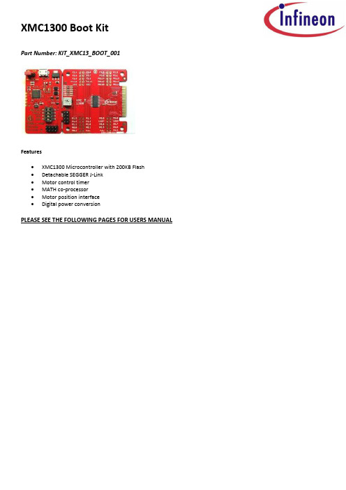
XMC1300 Boot KitPart Number: KIT_XMC13_BOOT_001Features∙XMC1300 Microcontroller with 200KB Flash∙Detachable SEGGER J-Link∙Motor control timer∙MATH co-processor∙Motor position interface∙Digital power conversionPLEASE SEE THE FOLLOWING PAGES FOR USERS MANUALXMC1300 CPU Card For XMC1000 FamilyCPU-13A-V1XMC1300 CPU CardBoard User's Manual Revision 2.0, 2013-12-18Edition 2013-12-18Published byInfineon Technologies AG81726 Munich, Germany© 2013 Infineon Technologies AGAll Rights Reserved.Legal DisclaimerThe information given in this document shall in no event be regarded as a guarantee of conditions or characteristics. With respect to any examples or hints given herein, any typical values stated herein and/or any information regarding the application of the device, Infineon Technologies hereby disclaims any and all warranties and liabilities of any kind, including without limitation, warranties of non-infringement of intellectual property rights of any third party.InformationFor further information on technology, delivery terms and conditions and prices, please contact the nearest Infineon Technologies Office ().WarningsDue to technical requirements, components may contain dangerous substances. For information on the types in question, please contact the nearest Infineon Technologies Office.Infineon Technologies components may be used in life-support devices or systems only with the express written approval of Infineon Technologies, if a failure of such components can reasonably be expected to cause the failure of that life-support device or system or to affect the safety or effectiveness of that device or system. Life support devices or systems are intended to be implanted in the human body or to support and/or maintain and sustain and/or protect human life. If they fail, it is reasonable to assume that the health of the user or otherTrademarks of Infineon Technologies AGAURIX™, C166™, CanPAK™, CIPOS™, CIPURSE™, EconoPACK™, CoolMOS™, CoolSET™, CORECONTROL™, CROSSAVE™, DAVE™, DI-POL™, EasyPIM™, EconoBRIDGE™, EconoDUAL™, EconoPIM™,EconoPACK™,EiceDRIVER™, eupec™, FCOS™, HITFET™, HybridPACK™, I²RF™, ISOFACE™, IsoPACK™, MIPAQ™, ModSTACK™,my-d™, NovalithIC™, OptiMOS™, ORIGA™, POWERCODE™, PRIMARION™, PrimePACK™, PrimeSTACK™, PRO-SIL™, PROFET™, RASIC™, ReverSave™, SatRIC™, SIEGET™, SINDRION™, SIPMOS™, SmartLEWIS™, SOLID FLASH™, TEMPFET™, thinQ!™, TRENCHSTOP™, TriCore™.Other TrademarksAdvance Design System™ (ADS) of Agilent Technologies, AMBA™, ARM™, MULTI-ICE™, KEIL™, PRIMECELL™, REALVIEW™, THUMB™, µVision™ of ARM Limited, UK. AUTOSAR™ is licensed by AUTOSAR development partnership. Bluetooth™ of Bluetooth SIG Inc. CAT-iq™ of D ECT Forum. COLOSSUS™, FirstGPS™ of Trimble Navigation Ltd. EMV™ of EMVCo, LLC (Visa Holdings Inc.). EPCOS™ of Epcos AG. FLEXGO™ of Microsoft Corporation. FlexRay™ is licensed by FlexRay Consortium. HYPERTERMINAL™ of Hilgraeve Incorporated. IEC™ of Commission Electrotechnique Internationale. IrDA™ of Infrared Data Association Corporation. ISO™ of INTERNATIONAL ORGANIZATION FOR STANDARDIZATION. MATLAB™ of MathWorks, Inc. MAXIM™ of Maxim Integrated Products, Inc. MICROTEC™, NUCLEUS™ of Mentor Graphics Corporation. MIPI™ of MIPI Alliance, Inc. MIPS™ of MIPS Technologies, Inc., USA. muRata™ of MURATA MANUFACTURING CO., MICROWAVE OFFICE™ (MWO) of Applied Wave Research Inc., OmniVision™ of OmniVision Technologies, Inc. Openwave™ Openwave Systems Inc. RED HAT™ Red Hat, Inc. RFMD™ RF Micro Devices, Inc. SIRIUS™ of Sirius Satellite Radio Inc. SOLARIS™ of Sun Microsystems, Inc. SPANSION™ of Spansion LLC Ltd. Symbian™ of Symbian Software Limited. TAIYO YUDEN™ of Taiyo Yuden Co. TEAKLITE™ of CEVA, Inc. TEKTRONIX™ of Tektr onix Inc. TOKO™ of TOKO KABUSHIKI KAISHA TA. UNIX™ of X/Open Company Limited. VERILOG™, PALLADIUM™ of Cadence Design Systems, Inc. VLYNQ™ of Texas Instruments Incorporated. VXWORKS™, WIND RIVER™ of WIND RIVER SYSTEMS, INC. ZETEX™ of Diodes Zetex Limited.Last Trademarks Update 2011-11-11Table of Contents1Overview (7)1.1Key Features (7)1.2Block Diagram (7)2Hardware Description (8)2.1Power Supply (8)2.2Reset (9)2.3Clock Generation (9)2.4Boot Option (9)2.5Debug Interface and virtual com port (9)2.6LED (9)2.7Potentiometer (10)2.8Application Card connector (10)3Production Data (12)3.1Schematics (12)3.2Layout and Geometry (15)3.3Bill of Material (15)List of FiguresFigure 1Block Diagram of XMC1300 CPU Card (7)Figure 2XMC1300 CPU Card (8)Figure 3Power Supply circuit (8)Figure 4LEDs circuit (10)Figure 5Potentiometer Circuit (10)Figure 6Pinout of the 2x30 pin edge connector (11)Figure 7Schematic 1 of 2 XMC1300 CPU Card (13)Figure 8Schematic 2 of 2 XMC1300 CPU Card (14)Figure 9XMC1300 CPU Card layout and geometry (15)List of TablesTable 1Debug connector X201 (9)Table 2LEDs Pinout (10)Table 3XMC1300 CPU Card (15)IntroductionThis document describes the features and hardware details of the XMC1300 CPU Card. This board is mounted with ARM® Cortex TM-M0 based XMC1300 Microcontroller from Infineon Technologies AG. This board is part of Infineon’s XMC1000 Application Kits1 OverviewThe XMC1300 CPU board (CPU-13A-V1) houses the XMC1300 Microcontroller and a 2x30 pin edge for application expansion. The board along with application cards (e.g. Colour LED Card, White LED Card) demonstrates the capabilities of XMC1300. The main use case for this board is to demonstrate the generic features of XMC1300 device including tool chain. The focus is safe operation under evaluation conditions. The board is neither cost nor size optimized and does not serve as a reference design.1.1 Key FeaturesThe XMC1300 CPU Card is equipped with the following features∙XMC1300 (ARM®Cortex TM-M0 based) Microcontroller, TSSOP38∙Connection to XMC1300 application cards via card edge connector∙Detachable J-Link debugger and UART virtual COM port, with micro USB connector∙Six user LEDs∙Potentiometer, connected to analog input P2.5∙Power supply via Micro-USB connector1.2 Block DiagramFigure 1 shows the functional block diagram of the XMC1300 CPU Card.Features include:−On board Debugger, for downloading and debugging of application code−Virtual com port for uart communication with terminal program e.g. Hyperterminal.−2x30 card edge connector, for extension to application card e.g. Colour LED Card and White LED Card.− 6 User LEDs connected to GPIO P0.0, P0.1, P0.6, P0.7, P0.8 and P0.9−Variable resistor R110 connected to Analog input P2.5−All the pins of XMC1300 are accessible via the connector JP101, JP102, JP103 and JP104Figure 1 Block Diagram of XMC1300 CPU Card2 Hardware DescriptionThe following sections give a detailed description of the hardware and how it can be used.Figure 2 XMC1300 CPU Card2.1 Power SupplyXMC1300 CPU Card is powered from the micro USB connector (5V); however, there is a current limit that can be drawn from the host PC through USB. If the CPU-13A-V1 board is used to drive other application board (e.g. Colour LED Card, White LED Card) and the total current required exceeds 500mA, then the board needs to be powered by external power supply connected to VDD and GND connection on board.The XMC1300 device can operate by power supply of 1.8V till 5.5Vdc. On this board, 5Vdc is used to power the XMC1300 device. However, if user wants to power the XMC1300 device with 3.3Vdc, then, set Jumper at JP201 to 3.3V side.Figure 3 Power Supply circuit2.2 ResetXMC1300 does not have a reset pin, hence, user can unplug and replug the USB cable to achieve power-on master reset.2.3 Clock GenerationNo external clock source is required. XMC1300 has two internal oscillators DCO1 and DCO2. DCO1 has a clock output of 64MHz. DCO2 is used to generate the standby clock running at 32.768KHz which used for Real Time Clock too. The main clock, MCLK and fast peripherial clock, PCLK, are generated from DCO1’s output.2.4 Boot OptionAfter power-on reset with master reset, XMC1300 device will enter different boot mode depend on the BMI (Boot Mode Index) value stored in XMC1300’s f lash configuration sector 0 (CS0). The BMI value pre-programmed on the XMC1300 device on CPU Card is User mode with debug enabled, hence, the XMC1300 device will start to run the application code in its embedded Flash after power on reset.2.5 Debug Interface and virtual com portXMC1300 CPU Card has on-board debugger which supports Serial Wire Debug (SWD) and Single Pin Debug (SPD) as debug interface. SPD is a proprietary debugging protocol from Infineon Technologies and it requires only 1 pin for debug communication. The debugger also provides a virtual COM port which support UART communication via P1.3 (rx-in) and P1.2 (tx-out) of XMC1300. There is a 2x5 pins Header Debug connector X201.Table 1 Debug connector X2012.6 LEDThe port pins P0.0, P0.1, P0.6, P0.7, P0.8 and P0.9 are connected to LED101, LED102, LED103, LED104, LED105 and LED106 respectively. The LED is turn on by output ‘L ow’ at the port pin.Figure 4 LEDs circuit2.7 PotentiometerXMC1300 CPU Card provides a potentiometer R110 for ease of use and testing of the on-chip analog to digital converter. The potentiometer is connected to the analog input P2.5. The analog output of the potentiometer is the same the VDDP voltage supplied to the XMC1300 device.Figure 5 Potentiometer Circuit2.8 Application Card connectorXMC1300 CPU Card has a 2x30 pins card edge connector. The mating connector is SAMTEC HSEC8-130-01-L-RA-XX.Figure 6 Pinout of the 2x30 pin edge connector3 Production Data3.1 SchematicsThis chapter contains the schematics for the XMC1300 CPU Card:∙Figure 7: CPU, Pin Headers, Potentiometer and LED and 60pin Edge connector ∙Figure 8: On-board Debugger, Power Supply3.2 Layout and GeometryFigure 9 XMC1300 CPU Card layout and geometry 3.3 Bill of Materialw w w.i n f i n e o n.c o m。
13001-13009的参数

MJE13001是小功率高压高速开关三极管,典型应用:荧光灯电子镇流器。
它采用TO-92封装,管脚排列如图:MJE13001主要参数:集电极-基极最高耐压VCBO=500V集电极-发射极最高耐压VCEO=400V发射极-基极最高耐压VEBO=9V集电极电流IC=0.3A耗散功率PC=7W结温Tj=150℃贮藏温度TSTG=-50~150℃直流放大系数HFE=8~403DD13001是硅NPN型小功率开关三极管,主要用于节能灯电子镇流器、手机充电器等开关电源电路。
3DD13001具有击穿电压高、反向漏电流小、开关速度快、饱和压降低、高温性能好等特点。
采用TO-251封装的3DD13001管脚排列如图:1脚:基极;2脚:集电极;3脚:发射极3DD13001主要参数:集电极最大耗散功率PCM=1.2W (Tamb=25℃)集电极最大允许电流ICM=0.2A集电极-基极反向击穿电压BVCBO=600V集电极-发射极反向击穿电压BVCEO=400V发射极-基极反向击穿电压BVEBO=7V结温Tj=150℃贮藏温度TSTG=-55~150℃直流放大系数=8~40MJE13002是高压高速开关三极管,国产同类型号为3DD13002。
它主要用于电子节能灯、日光灯电子镇流器,以及其它开关电路中。
MJE13002(3DD13002)采用TO-126封装的外形尺寸和管脚排列如图:MJE13002(3DD13002)主要参数VCBO=600VVCEO=400VVEBO=7VIC=1APC=1.2WTj=150℃TSTG=-55~150℃ICBO=100μAIEBO=100μAHFE=10~40VCE(sat) =0.5VVBE(sat) =1.0VfT=4MHzTf=0.6μsMJE13003是主要用于节能灯及荧光灯电子镇流器的高反压大功率开关三极管,硅NPN 型,采用TO-126封装,它的外形和管脚排列如下:MJE13003主要参数集电极-基极电压VCBO 700 V集电极-发射极电压VCEO 400 V发射极-基极电压VEBO 9V集电极电流IC 2.0 A集电极耗散功率PC 40 W最高工作温度Tj 150 °C贮存温度Tstg -65-150 °C集电极-基极截止电流ICBO (VCB=700V) 100 μA集电极-发射极截止电流ICEO (VCE=400V,IB=0) 250 μA集电极-发射极电压VCEO (IC=10mA,IB=0) 400 V发射极-基极电压VEBO (IE=1mA,IC=0) 9 V直流电流放大倍数5~403DD13005是高反压大功率开关三极管,硅材料NPN型,平面扩散工艺制造,开关速度快,耐压高。
NXP mcu
TinyM0核心板电路为LPC111x芯片的最小系统,硬件支持2.54mm间距的 标准排针。用户可以将TinyM0核心板配套自行设计的底板进行产品开发。 ● 支持多款芯片
和16位竞争产品的2至4倍。
Cortex-M0内核
● 32位ARM RISC处理器,16位Thumb指令集; ● 功耗与面积高度优化,设计专用于低成本、低功耗场合; ● 24位SysTick定时器; ● 32位硬件乘法器; ● 中断现场自动保存,有处理决定性、固定延迟的中断能力; ● 系统接口支持小端或字节不变的大端数据访问; ● SWD串行线调试。
LPC1300选型表:
器件型号 LPC1343 LPC1342 LPC1313 LPC1311
Flash (KB) 32 16 32 8
SRAM(KB) 8 4 8 2
USB 2.0 Device Device
-
I2C(Fast+) 1 1 1 1
ADC 8ch/10bit 8ch/10bit 8ch/10bit 8ch/10bit
置的新型开漏工作模式
LPC1100
◎ 四个通用计数器/计数器 ◎ 可编程的看门狗定时器(WDT),带锁死功能 ◎ 系统计时器 ◎ 各外设自带时钟分频器,有利于降低功耗
芯片特色:
Cortex-M0处理器性能 ● Cortex-M0微控制器可以轻松超越高端8位和16位器件的
性能水平; ● 内核额定性能为0.9DMIPS/MHz,相当于与其最接近的8位
爱森莱特198901快速连接器速度调节器说明说明书

Eaton 198901Eaton Moeller® series Rapid Link - Speed controllers, 5.6 A, 2.2 kW, Sensor input 4, Actuator output 2, 180/207 V DC, Ethernet IP, HAN Q4/2, with manual override switchEaton Moeller® series Rapid Link Speed controller198901157 mm270 mm 220 mm 3.59 kgIEC/EN 61800-5-1 RoHS UL 61800-5-1 UL approval CERASP5-5421EIP-412R000S1Product NameCatalog NumberProduct Length/Depth Product Height Product Width Product Weight Certifications Catalog Notes Model Code3 fixed speeds and 1 potentiometer speedcan be switched over from U/f to (vector) speed control Connection of supply voltage via adapter cable on round or flexible busbar junction480 VIs the panel builder's responsibility. The specifications for the switchgear must be observed.400 V AC, 3-phase480 V AC, 3-phaseMeets the product standard's requirements.2.2 kW500 VMeets the product standard's requirements.-40 °C380 VControl unitKey switch position HANDTwo sensor inputs through M12 sockets (max. 150 mA) for quick stop and interlocked manual operation2 Actuator outputsManual override switchIGBT inverterKey switch position OFF/RESETThermo-click with safe isolationInternal DC linkPTC thermistor monitoringSelector switch (Positions: REV - OFF - FWD)Key switch position AUTOPC connection0 Hz200 %, IH, max. starting current (High Overload), For 2 seconds Generation Change RA-SP to RASP5Configuration to Rockwell PLC for Rapid LinkGeneration Change RASP4 to RASP5Generation change from RA-MO to RAMO 4.0Generation change RAMO4 to RAMO5Generation change from RA-SP to RASP 4.0Rapid Link 5 - brochureDA-SW-drivesConnect - InstallationshilfeDA-SW-Driver DX-CBL-PC-3M0DA-SW-USB Driver DX-COM-STICK3-KITDA-SW-drivesConnectDA-SW-drivesConnect - installation helpDA-SW-USB Driver PC Cable DX-CBL-PC-1M5Material handling applications - airports, warehouses and intra-logistics ETN.RASP5-5421EIP-412R000S1.edzIL034093ZUrasp5_v31.stpramo5_v31.dwgDA-DC-00004508.pdfDA-DC-00004514.pdfDA-DC-00004184.pdfDA-DC-00003964.pdfeaton-bus-adapter-rapidlink-speed-controller-dimensions-002.eps eaton-bus-adapter-rapidlink-speed-controller-dimensions-005.eps eaton-bus-adapter-rapidlink-speed-controller-dimensions-003.eps eaton-bus-adapter-rapidlink-speed-controller-dimensions-004.epsMains voltage - max10.11 Short-circuit ratingRated operational voltage10.4 Clearances and creepage distancesOutput at quadratic load at rated output voltage - max Output voltage - max10.2.3.1 Verification of thermal stability of enclosures Ambient storage temperature - minMains voltage - minFitted with:Output frequency - minStarting current - max Applikasjonsmerknader BrosjyrereCAD model Installeringsinstruksjoner mCAD model SertifiseringsrapporterTegningerevery 20 seconds, Power sectionRated conditional short-circuit current (Iq)10 kAAmbient operating temperature - max40 °CCommunication interfaceEthernet IP, built inAssigned motor power at 115/120 V, 60 Hz, 1-phase3 HPOutput frequency - max500 HzSwitching frequency8 kHz, 4 - 32 kHz adjustable, fPWM, Power section, Main circuitFeaturesParameterization: drivesConnectParameterization: KeypadParameterization: drivesConnect mobile (App) Parameterization: FieldbusAmbient operating temperature - min-10 °CBraking current≤ 0.6 A (max. 6 A for 120 ms), Actuator for external motor brakeNumber of HW-interfaces (serial TTY)10.6 Incorporation of switching devices and componentsDoes not apply, since the entire switchgear needs to be evaluated.Nominal output current I2N5.6 A10.2.6 Mechanical impactDoes not apply, since the entire switchgear needs to be evaluated.10.3 Degree of protection of assembliesDoes not apply, since the entire switchgear needs to be evaluated.Product categorySpeed controllerRadio interference classC2, C3: depending on the motor cable length, the connected load, and ambient conditions. External radio interference suppression filters (optional) may be necessary.C1: for conducted emissions onlyHeat dissipation capacity Pdiss0 WRated control voltage (Uc)180/207 V DC (external brake 50/60 Hz)24 V DC (-15 %/+20 %, external via AS-Interface® plug)Assigned motor power at 460/480 V, 60 Hz, 3-phase3 HPNumber of HW-interfaces (RS-422)Mains current distortion120 %ProtocolEtherNet/IP10.9.2 Power-frequency electric strengthIs the panel builder's responsibility.Overvoltage categoryIIIDegree of protectionIP65NEMA 12Ambient storage temperature - max70 °CRated impulse withstand voltage (Uimp)2000 VConnectionPlug type: HAN Q4/2Overload currentAt 40 °CFor 60 s every 600 sFunctions1 potentiometer speedFor actuation of motors with mechanical brake3 fixed speedsOutput at linear load at rated output voltage - max2.2 kWMains voltage tolerance380 - 480 V (-10 %/+10 %, at 50/60 Hz)Leakage current at ground IPE - max3.5 mAConverter typeU converter10.2.2 Corrosion resistanceMeets the product standard's requirements.Supply frequency50/60 Hz10.2.4 Resistance to ultra-violet (UV) radiationMeets the product standard's requirements.10.2.7 InscriptionsMeets the product standard's requirements.Shock resistance15 g, Mechanical, According to IEC/EN 60068-2-27, 11 ms, Half-sinusoidal shock 11 ms, 1000 shocks per shaftApplication in domestic and commercial area permittedYesNumber of inputs (analog)Number of phases (output)310.12 Electromagnetic compatibilityIs the panel builder's responsibility. The specifications for the switchgear must be observed.10.2.5 LiftingDoes not apply, since the entire switchgear needs to be evaluated.Number of HW-interfaces (RS-485)1Number of HW-interfaces (industrial ethernet)2Efficiency98 % (η)System configuration typeCenter-point earthed star network (TN-S network)AC voltagePhase-earthed AC supply systems are not permitted.10.8 Connections for external conductorsIs the panel builder's responsibility.ProtectionFinger and back-of-hand proof, Protection against direct contact (BGV A3, VBG4)Braking voltage280/207 V DC -15 % / +10 %, Actuator for external motor brakeApplication in industrial area permittedYesClimatic proofing< 95 %, no condensationIn accordance with IEC/EN 5017810.9.3 Impulse withstand voltageIs the panel builder's responsibility.Overload current IL at 150% overload8.4 AInput current ILN at 150% overload5.3 ANumber of HW-interfaces (RS-232)Number of inputs (digital)4Current limitationAdjustable, motor, main circuit0.5 - 5.6 A, motor, main circuitCable lengthC3 ≤ 25 m, maximum motor cable lengthC1 ≤ 1 m, maximum motor cable lengthC2 ≤ 5 m, maximum motor cable length10.5 Protection against electric shockDoes not apply, since the entire switchgear needs to be evaluated.Mounting positionVerticalMains switch-on frequencyMaximum of one time every 60 seconds10.13 Mechanical functionThe device meets the requirements, provided the information in the instruction leaflet (IL) is observed.10.9.4 Testing of enclosures made of insulating materialIs the panel builder's responsibility.Heat dissipation per pole, current-dependent Pvid0 WElectromagnetic compatibility1st and 2nd environments (according to EN 61800-3)Resolution0.1 Hz (Frequency resolution, setpoint value)Assigned motor power at 460/480 V, 60 Hz3 HPRelative symmetric net voltage tolerance10 %Rated operational current (Ie)5.6 A at 150% overload (at an operating frequency of 8 kHz and an ambient air temperature of +40 °C)Number of outputs (analog)Rated operational power at 380/400 V, 50 Hz, 3-phase2.2 kWNumber of HW-interfaces (USB)Operating modeBLDC motorsU/f controlSensorless vector control (SLV)Synchronous reluctance motorsPM and LSPM motorsRated frequency - min45 HzDelay time< 10 ms, Off-delay< 10 ms, On-delayNumber of outputs (digital)2Power consumption58 W10.2.3.2 Verification of resistance of insulating materials to normal heatMeets the product standard's requirements.10.2.3.3 Resist. of insul. mat. to abnormal heat/fire by internal elect. effectsMeets the product standard's requirements.Number of HW-interfaces (other)Rated frequency - max66 HzVibrationResistance: 57 Hz, Amplitude transition frequency on accelerationResistance: 10 - 150 Hz, Oscillation frequencyResistance: 6 Hz, Amplitude 0.15 mmResistance: According to IEC/EN 60068-2-6Short-circuit protection (external output circuits)Type 1 coordination via the power bus' feeder unit, Main circuit10.7 Internal electrical circuits and connectionsIs the panel builder's responsibility.Braking torqueAdjustable to 100 % (I/Ie), DC - Main circuit≤ 30 % (I/Ie)Relative symmetric net frequency tolerance10 %10.10 Temperature riseThe panel builder is responsible for the temperature rise calculation. Eaton will provide heat dissipation data for the devices.Number of HW-interfaces (parallel)Assigned motor power at 230/240 V, 60 Hz, 1-phase3 HPInterfacesMax. total power consumption from AS-Interface® power supply unit (30 V): 250 mANumber of slave addresses: 31 (AS-Interface®) Specification: S-7.4 (AS-Interface®)Number of phases (input)3Eaton Corporation plc Eaton House30 Pembroke Road Dublin 4, Ireland © 2023 Eaton. Med enerett.Eaton is a registered trademark.All other trademarks are property of their respectiveowners./socialmedia36.6 W at 25% current and 0% speed 38.1 W at 25% current and 50% speed 42 W at 50% current and 0% speed 42.5 W at 50% current and 90% speed 44.2 W at 50% current and 50% speed 55.9 W at 100% current and 0% speed 58.3 W at 100% current and 90% speed 60.4 W at 100% current and 50% speed 0Above 1000 m with 1 % performance reduction per 100 m Max. 2000 mHeat dissipation at current/speed Number of interfaces (PROFINET)Altitude。
- 1、下载文档前请自行甄别文档内容的完整性,平台不提供额外的编辑、内容补充、找答案等附加服务。
- 2、"仅部分预览"的文档,不可在线预览部分如存在完整性等问题,可反馈申请退款(可完整预览的文档不适用该条件!)。
- 3、如文档侵犯您的权益,请联系客服反馈,我们会尽快为您处理(人工客服工作时间:9:00-18:30)。
广州周立功单片机发展有限公司
第 11 章
11.6 寄存器描述
UART的寄存器结构如表 11.2所示。除数锁存器访问位(DLAB)位于U0LCR[7]中,可使能 除数锁存器的访问。
RO WO
0x000 0x000
n/a n/a
U0DLL效字节。 整个分频器用于 产生小数波特率分频器的波特 率 除数锁存 MSB。波特率除数值
0x01
当 DLAB=1
U0DLM
R/W
0x004
的最高有效字节。 整个分频器用 于产生小数波特率分频器的波 特率 中断使能寄存器。 包含 7 个潜在
[1]
CTS DCD
[1]
RI [1]
[1] 只用于 LQFP48 封装。
11.5 时钟和功率控制
UART 模块的时钟和功率由以下两个寄存器控制: 1) UART 模块可通过系统 AHB 时钟控制寄存器的位 12 (见表 “系统 AHB 时钟控制寄存器” ) 使能或关闭。 2)UART 外设时钟 UART_PCLK 在 UART 时钟分频器寄存器(见表“UART 时钟分频寄存 器” )中使能。该时钟供 UART 波特率发生器使用。
11.2 基本配置
配置 UART 模块需使用以下寄存器: 1)管脚:在使能 UART 时钟前,必须先对 IOCONFIG 寄存器模块(见“I/O 配置寄存器 IOCON_PIOn”小节)中的 UART 管脚进行配置。 2)功率:设置 SYSAHBCLKCTRL 寄存器中的位 12(见表“系统 AHB 时钟控制寄存器” ) 。 3)外设时钟:通过对 UARTCLKDIV 寄存器(见表“UART 时钟分频寄存器” )进行编程, 使能 UART 外设时钟。
表 11.2 寄存器概述:UART(基址:0x4000 8000) 名称 访问 地址偏移量 描述 接收缓冲寄存器。 包含下一个要 读取的已接收字符 发送保持寄存器。 在此写入下一 个要发送的字符 除数锁存 LSB。 波特率除数值的 复位值[1] 注释 当 DLAB=0 当 DLAB=0
U0RBR U0THR
LPC1300 用户手册 i
©2010 Guangzhou ZLGMCU Development CO., LTD. i
广州周立功单片机发展有限公司
第 11 章
第11章 通用异步收发器(UART)
11.1 本章导读
所有 LPC1300 系列 Cortex-M3 微控制器的 UART 模块都相同。但是,只有 LQFP48 封装提 供了 DSR 、 DCD 和 RI Modem 信号的管脚配置。
11.4 管脚描述
表 11.1 管脚 类型 输入 输出 输出 输出 输入 输入 输入 输入 串行输入管脚。串行接收数据 串行输出管脚。串行发送数据 请求发送。RS-485 方向控制管脚 数据终端就绪 数据设置就绪 清除发送 数据载波检测 铃响指示 UART 管脚描述 描述
RXD TXD
RTS
DTR
DSR
0x00
当 DLAB=1
U0IER
R/W
0x004
的 UART 中断对应的各个中断 使能位 中断 ID 寄存器。识别等待处理 的中断
0x00
当 DLAB=0
U0IIR U0FCR U0LCR U0MCR U0LSR U0MSR U0SCR U0ACR U0FDR -
RO WO R/W R/W RO RO R/W R/W R/W -
0x008 0x008 0x00C 0x010 0x014 0x018 0x01C 0x020 0x024 0x028 0x02C
广州周立功单片机发展有限公司
目录
第 11 章 通用异步收发器(UART) ................................................................................. 1
11.1 11.2 11.3 11.4 11.5 11.6 本章导读 .............................................................................................................................1 基本配置 .............................................................................................................................1 特性.....................................................................................................................................1 管脚描述 .............................................................................................................................1 时钟和功率控制 .................................................................................................................1 寄存器描述 .........................................................................................................................2 11.6.1 UART接收缓冲器寄存器 ..........................................................................................3 11.6.2 UART发送器保持寄存器 ..........................................................................................3 11.6.3 除数锁存器LSB和MSB寄存器 .................................................................................4 11.6.4 UART中断使能寄存器 ..............................................................................................4 11.6.5 UART中断标识寄存器 ..............................................................................................5 11.6.6 UART FIFO控制寄存器.............................................................................................7 11.6.7 UART线控寄存器 ......................................................................................................7 11.6.8 UART Modem控制寄存器 .........................................................................................8 11.6.9 UART线状态寄存器 ................................................................................................10 11.6.10 UART Modem状态寄存器 .......................................................................................12 11.6.11 UART高速缓存寄存器 ............................................................................................12 11.6.12 UART Auto-baud控制寄存器 ..................................................................................13 11.6.13 自动波特率(Auto-baud) ......................................................................................13 11.6.14 Auto-baud模式 ..........................................................................................................14 11.6.15 UART小数分频器寄存器 ........................................................................................15 11.6.16 UART发送使能寄存器 ............................................................................................18 11.6.17 UART RS485 控制寄存器 .......................................................................................19 11.6.18 UART RS-485 地址匹配寄存器 ..............................................................................20 11.6.19 UART1 RS-485 延时值寄存器 ................................................................................20 11.6.20 RS-485/EIA-485 模式的操作...................................................................................20 11.7 结构...................................................................................................................................21