德马格FDR电动葫芦参数
德马格电动葫芦说明书
德马格起重机械有限公司DCS-PRO环链电动葫芦检测证书共2页识别号:235 309 44版本:0104第1页分类号:787 4115XB检测符合出厂证明2."1DIN EN 10204标准生产商:德马格起重机械有限公司订货方:hisINDUSTRIEHANDLING订单号:550901客户号:C8."064设备型号:DCS-PRO 2-250 1/1 H5 VS16-30工厂编号:最大行程:最小速度:0."15米/分电压:380-480V50/60Hz/cs链条数:1/1安全工作负荷:0."25吨防护等级:IP55精行程:16米/分额定速度:16米/分部分负载最大速度:30米/分检测电压:400V50/60Hz控制器以95%的额定电压和25%的过载测试德马格电动葫芦DCS-PRO,无任何异常,防滑离合器正常运转。
电机工厂检测证书电机型号:ZNK 71 B 43相鼠笼型异步电动机功率因数:0."5接通时间:60转数(1分钟):2480是否连接:是频率:50/60功率(kW):0."73电压(V):380-480电流(A):3."1最高环境温度(℃):40可承受绕组温度(K):105绝缘等级:F绝缘电阻定子:≧1MOhm温度监控:M绝缘强度:1."2×(2U+1000V)≦30m A约1秒备注:德马格起重机械有限公司DCS-PRO环链电动葫芦检测证书共2页识别号:235 309 44版本0104第2页分类号:787 4115XB起重吊钩检测证书吊钩类型:简易吊钩起重吊钩标识供应商商标:PS起重吊钩检测最大测试力(k N):(变形<0."25%)材料特性:34CrMo4 EN10083化学成分在-20℃的性能RelA(≥)J(≥)MPa(≥)强度等级:V起重吊钩号码:2标准:DIN15400融化编号:吊钩最大承受力:C(≤)Si(≤)MnP(≤)S(≤)Cr(≤)Mo(≤)R meMPa0."370."400."60-0."900."0350."0350."90-1."200."15-0."30实际功率在额定功率范围内精确性:所有数据都在允许误差范围之内起重吊钩无影响使用的表面裂纹和裂痕。
电动葫芦 技术参数

电动葫芦的技术参数
电动葫芦的技术参数包括额定起重量、起升高度、跨度和工作级别等。
1.额定起重量:指起重电动葫芦能吊起的物料连同可分吊具或属具(如抓斗、电磁吸盘、平衡梁等质量的总和。
2.起升高度:指电动葫芦从地面到吊钩的最大垂直提升距离。
3.跨度:指电动葫芦的轮距,即其两侧支撑轮之间的距离。
4.工作级别:反映了电动葫芦的工作强度,表明其使用频率和负载情况。
以上是电动葫芦的技术参数,如需了解更多信息,请咨询专业人士。
德马格起重机械(上海)有限公司重磅推出新品——第二代DC环链电动葫芦

德马格起重机械(上海)有限公司重磅推出新品——第二代DC
环链电动葫芦
供稿/德马格起重机械(上海)有限公司;王芝兵采编/邹铁汉;张韦微
【期刊名称】《起重运输机械》
【年(卷),期】2024()7
【摘要】德马格起重机在欧洲最大室内物流展览会LogiMAT2024上发布了风靡全球,且久经实际应用验证的DC系列环链电动葫芦的下一代——DC-II系列。
德马格起重机于20年前首次推出了DC系列环链电动葫芦,现已堪称环链电动葫芦产品的行业标杆。
在开发第二代DC环链电动葫芦时,德马格充分考虑了近年来的发展趋势,以引领该产品系列走向未来。
现场观众可以在LogiMAT2024德马格起重机的展台上了解到最新的起重技术。
【总页数】3页(P2-4)
【作者】供稿/德马格起重机械(上海)有限公司;王芝兵采编/邹铁汉;张韦微
【作者单位】不详
【正文语种】中文
【中图分类】TH2
【相关文献】
1.德马格公司的新型DC环链电动葫芦
2.德马格起重机械(上海)有限公司DC型环链电动葫芦
3.德马格推出DCS-Pro 10变频调速环链电动葫芦系列
4.德马格起
重机械(上海)有限公司环链电动葫芦的迭代创新5.德马格起重机械(上海)有限公司DVR钢丝绳电动葫芦
因版权原因,仅展示原文概要,查看原文内容请购买。
电动葫芦的参数

电动葫芦的参数:
起重量:0.25t-60t 起升高度:3m-30m 工作级别:M3 运行速度:20(30)m/min 起升速度:8m/min
山东神华机械
电动葫芦的参数
电动葫芦是一种特种起重设备,安装于天车、 龙门吊之上,电动葫芦具有体积小,自重轻, 操作简单,使用方便等特点,用于工矿企业, 仓储码头等场所。
电动葫芦组成结构:
起重量一般为 0.1~80吨,起升高度为3~30米。由 电动机、传动机构和卷筒或链轮组成,分为钢丝绳电动 葫芦和环链电动葫芦两种。其中环链电动葫芦分为进口 和国产两种;钢丝绳电动葫芦分单速提升、双速提升; 微型电动葫芦、卷扬机、多功能提升机。
电动葫芦主要参数文字说明部分

电动葫芦主要参数文字说明部分.一、文字说明部分1、产品概述D型系列钢丝绳电动葫芦系在原CD、MD 型1基础上的改进型产品。
它具有结构紧凑、轻巧、安全可靠、零部件通用程度大,互换性强、单重起重能力高、维修方便等特点,是目前用途广泛,深受欢迎的轻型起重设备。
该葫芦有固定式和小车式两类。
固定式又分为“A、A、A、A”四种型式,见图3,可直接安 4 123装在构架上使用;小车式具有运行功能,可安装在轨道上使用。
CD型为単速起升,MD型为常速11和慢速两档起升。
本厂主要生产载重0.25t~20t,起什高度3m~30m系列电动葫芦,亦可根据您的需要设计、制造非标系列电动葫芦。
2、主要用途小车式葫芦可安装在多种形式的起重机上或悬挂在工字钢梁上,直线或曲线往复吊运重物,固定式葫芦可安装在固定支撑上作垂直的或不同角度的卷扬起吊用。
本产品广泛用于工矿企业、铁路、码头、仓是目前生产作业中改善劳料场等场所,库、.动条件、提高劳动效率的必备机械。
适用范围及工作条件3、℃,湿度~+40本产品适用于在温度-25℃爆炸危,≤85%海拔1000m以下,无火灾,禁止吊运融险和腐蚀性介质的环境中工作。
化金属和有毒、易燃、易爆物品。
本产品所;工380V适用的电源为交流三相、50HZ、使用中机构工作级别每提高作类型为中级。
20%。
一级,其额定起吊量必须相应降低产品规格型号及其外形结构4、4.规格型号及外形结构1D(C291/ D电动小车起升高度 9mA下固定式22t 额定起重MD 为常速(CD慢速)/常速11型电动葫芦规格型号参数技术参CD4.2 MD 114数和外形安装尺寸见表.4.3 外形结构图见图1~图155、传动结构与工作原理CD MD型电动葫芦主要由三部分组11成,一为提升机构;二为运行机构(固定式则无);三为电器装置。
5.1 起什机构起升机构由起升电机通过联轴器经减速器空心轴驱动卷筒旋转,使绕在卷筒上的钢丝绳带动吊钩装置上升或下降。
德马格、科尼、国产HM葫芦对比

参数对照表Kone 5吨固定式葫芦
全封闭内置于卷筒的结构科尼德马格
起升高度9米10米
起升速度5/0.83m/min6/1m/min
工作级别M5M5
外观油漆粉末喷涂
防护等级IP55IP55
电机类型双速双速
接电持续率≥55%≥55%
齿面硬度≥HRC60≥HRC60
电机制动器电磁盘式刹车电磁盘式刹车
噪音低低
安全监控单元有有
参考价格10万/台10万/台
1马达的拆装非常困难,需要特殊工具
2马达接线、检查需要将整个马达拆卸下来
3马达散热非常不好,频繁使用容易发热
4特殊设计的马达,维修成本高
5镀锌钢丝绳,僵性大,频繁使用容易坏。
6钢丝绳破断来了2190NM, 非标钢丝绳,备件不容易买。
7专门的电气控制元件,备件贵
德马格 5吨固定式葫芦国产HM系列 5吨固定式葫芦德马格的开放式结构
9米
7/0.7m/min
M5
油漆
IP55
双电机(子母)
≥40%
≥HRC55
锥环刹车
≤80dB
无
3.5万/台
1开放式设计,标准,通用见所附总图
2接线检查非常简单,直观
3散热性能好,适合频繁点动操作
4不需要专用工具,维修成本低
5起重机标准钢丝绳,德国进口。
6标准钢丝绳,维修成本低
7全部采用欧洲通用的电气元件(ABB,西门子,TE等)
列 5吨固定式葫芦。
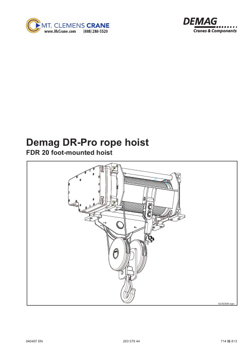
德马格行车DR20 Pro技术数据
Code 02
FDR with solo electrical equipment for use as a solo travelling hoist. DSE-10R control pendant with control cable included.
Code 03
As for code 01 but control via a radio control system DRC.
20357944.indd/011206
4
Selection criteria
Selection table
Range
Group of mechanisms FEM/ISO
1Am/M4 2m/M5 3m/M6 4m/M7
1Am/M4 2m/M5 3m/M6 4m/M7
DR 20
1Am/M4 2m/M5 3m/M6 4m/M7
Hook paths
Length of hoist unit 2/1
5
Motor selection depending on reeving arrangement and SWL
6
Foot-mounted hoist 2/1 reeving
8
Mounting position C3
8
Mounting position B4
10
Foot-mounted hoist 4/1 reeving
Code 04
As for code 02 but control via a radio control system DRC.
Code 05
FDR with fitted parallel “in” interface
德马格电动葫芦 链条限位

德马格电动葫芦链条限位
德马格电动葫芦是一种常用的起重设备,它通常用于工业和建筑领域。
链条限位是指在电动葫芦的设计中加入了限位装置,以确保链条在使用过程中不会超出安全范围,从而保障操作人员和设备的安全。
首先,让我们从技术角度来看链条限位的作用和原理。
链条限位通常由传感器和控制系统组成,传感器可以监测链条的位置和张力,一旦链条超出预设的范围或者出现异常情况,控制系统会立即停止葫芦的运行,以避免意外发生。
这种设计可以有效地防止链条的过度拉伸或扭曲,保证了电动葫芦的正常运行和使用安全。
其次,从安全角度来看,链条限位的存在对于操作人员和周围环境都是非常重要的。
通过限位装置,可以避免因链条超出范围而导致的意外伤害和设备损坏。
这种安全设计符合现代起重设备的安全标准和要求,提高了工作场所的安全性和生产效率。
另外,从实际应用角度来看,链条限位的设计也使得电动葫芦更加方便和可靠。
操作人员无需过多地担心链条的位置和状态,可以更加专注地完成起重作业。
同时,这种设计也减少了对设备的维
护和保养,延长了电动葫芦的使用寿命,降低了维护成本。
总的来说,德马格电动葫芦的链条限位设计在技术、安全和实
际应用层面都具有重要意义。
它不仅保障了设备和操作人员的安全,也提高了设备的可靠性和工作效率。
这种设计体现了现代起重设备
追求安全、高效和便利的发展趋势。
- 1、下载文档前请自行甄别文档内容的完整性,平台不提供额外的编辑、内容补充、找答案等附加服务。
- 2、"仅部分预览"的文档,不可在线预览部分如存在完整性等问题,可反馈申请退款(可完整预览的文档不适用该条件!)。
- 3、如文档侵犯您的权益,请联系客服反馈,我们会尽快为您处理(人工客服工作时间:9:00-18:30)。
Technical dataDemag FDR-Bas rope hoistFDR-Bas 3 - 5 - 10 foot-mounted hoist121211 en CN203 735 44714 IS 813220373544_e n _121211 © D e m a g C r a n e s & C o m p o n e n t sContentsDesign overview3Explanation of size designations/type assignment 3Selection criteria 4Selection table 5FDR-Bas 3- 2/1, H12, H20, H30 foot-mounted hoist, m ounting p osition A 6- 4/1, H12, H20 foot-mounted hoist, m ounting p osition A 7- 4/1, H30 foot-mounted hoist, mounting position A8- 4/1, H12, H20, H30 foot-mounted hoist, m ounting p osition B 9FDR-Bas 5- 2/1, H12, H20, H30 foot-mounted hoist, m ounting p osition A 10- 4/1, H12, H20 foot-mounted hoist, m ounting p osition A 11- 4/1, H30 foot-mounted hoist, mounting position A12- 4/1, H12, H20, H30 foot-mounted hoist, m ounting p osition B 13FDR-Bas 10- 2/1, H12, H20, H30 foot-mounted hoist, m ounting p osition A 14- 4/1, H12, H20 foot-mounted hoist, m ounting p osition A 15- 4/1, H30 foot-mounted hoist, mounting position A16- 4/1, H12, H20, H30 foot-mounted hoist, m ounting p osition B 17DR 3 - 5 - 10 motor data with pole-changing hoist drives18320373544_e n _121211© D e m a g C r a n e s & C o m p o n e n t sDesign overviewExplanation of size designations/type assignment1) Code CC - with contactor controlNC - without contactor control420373544_e n _121211© D e m a g C r a n e s & C o m p o n e n t s Selection criteriaExampleLoad capacity 5 t Load spectrum “Medium” from table Lifting speed 6 m/min Creep lifting speed 1 m/min Reeving 4/1Average hook path 3 m No. of cycles/hour 20Working time/day 8 hoursThe average operating time per working day is estimated or calculated as follows:The size of the hoist is determined by the loadspectrum, average operating time per working day, load capacity and reeving.L o a d c a p a c i t yOperating time L o a d c a p a c i t yOperating timeL o a d c a p a c i t yOperating time Operating timeVery heavy dead loadSmall partial load Small dead loadLarge partial load Medium partial load Medium dead loadHeavy dead loadL o a d c a p a c i t y4 Very heavyHoist units which are usually subject to maximum or almost maximum loads.3 HeavyHoist units which are usually subject to medium loads but frequently to maximum loads.2 MediumHoist units which are usually subject to small loads but rather often to maximum loads.The load spectrum(in most cases estimated) can be evaluated ac-cording to the definitions below:1 LightHoist units which are usually subject to very small loads and in exceptional cases only to maximum loads. 1. What are the operating conditions?2. What is the specified safe working load?3. To what height must the load be lifted?4. What is the required lifting speed?5. Do the loads need to be lifted and lowered withgreat accuracy?6. Is horizontal load travel necessary?7.How is the hoist to be controlled?For the medium load spectrum and an average daily operating time of 2,66 hours, the table above shows group 2m. For a load capacity of 5 t and 4/1 rope reeving, the following table indicates hoist size DR-Bas 5 - 5.Operating time/day = 2 · average hook path · no. of cycles/hour · working time/day=60 · hoist speedOperating time/day =2 ·3 · 20 · 8= 2,66 hours60 · 6The group is determined by the load spectrum and operating time.Load spectrum Average operating time per working day in hours 1Light 2-44-88-16more than 163Heavy 0,5-11-22-44-84Very heavy0,25-0,50,5-11-22-4Group of mechanisms toFEM1Am 2m 3m 4m ISOM4M5M6M71) Gearbox service life 20 % higher than the FEM full-load service life520373544_e n _121211© D e m a g C r a n e s & C o m p o n e n t s Selection tableNote:If no specifications for the mounting position or rope lead-off are included in an order, mounting position A with rope lead-off 1 is supplied as standard.Range Group of mechanisms Load capacityHook pathLifting speed vLifting Motor sitzFEMISO[t][m][m/min]DR-Bas 32/1MH-Bas 112A1Am M4212; 20; 3010/1,62m M51,612/23mM61,254mM714/11Am M446; 10; 155/0,8MH-Bas 112A2m M53,26/13m M62,54mM72DR-Bas 52/11Am M43,212; 20; 3010/1,6MH-Bas 132A2m M52,512/23mM624mM71,64/11Am M46,36; 10; 155/0,8MH-Bas 132A2m M556/13m M644mM73,2DR-Bas 102/11Am M46,312; 20; 308/1,2MH-Bas 160A2m M5510/1,63mM644mM73,24/11Am M412,56; 10; 154/0,6MH-Bas 160A2m M5105/0,83m M684mM76,3620373544_e n _121211© D e m a g C r a n e s & C o m p o n e n ts FDR-Bas 3 - 2/1, H12, H20, H30 foot-mounted hoist, m ounting p osition A43414444.epsGroup of mechanisms to FEM/ISO 1Am/M4, 2m/M5, 3m/M6, 4m/M7Dimensions in mmC1240d2 2)180FDR-Bas 3 dimensions in mm1) Weight data including rope, motor and bottom block2) In root of grooveSee page 21 for motordimensions F, G and LRope drum H12H20H30Foot distance R 590,5815,51095,5Hook travel n2168280,5421Rope lead-off point at highest hook position m2/centre R144256,5396,5Main dimension l1, limit-switch side/centre R 367,0479,5619,5Main dimension l2, gearbox side/centre R 357,5470,0610,0Distance l3, bracket frame bore hole 6118361116Rope dia. D 7Pitch P 7,8Weight 1) [kg]227242266720373544_e n _121211© D e m a g C r a n e s & C o m p o n e n tsFDR-Bas 3 - 4/1, H12, H20 foot-mounted hoist, m ounting p osition A43414544.epsFDR-Bas 3 dimensions in mmRope drum H12H20Foot distance R 590,5815,5Hook travel n484140Rope lead-off point at highest hook position m4/centre R23135Main dimension l1, limit-switch side/centre R 367,0479,5Main dimension l2, gearbox side/centre R 357,5470,0Distance l3, bracket frame bore hole 611836Rope dia. D 7Pitch P 7,8Weight 1) [kg]246264Group of mechanisms to FEM/ISO 1Am/M4, 2m/M5, 3m/M6, 4m/M7Dimensions in mmC1240d2 2)1801) Weight data including rope, motor and bottom block 2) In root of grooveSee page 21 for motordimensions F, G and L820373544_e n _121211© D e m a g C r a n e s & C o m p o n e n ts FDR-Bas 3 - 4/1, H30 foot-mounted hoist, mounting position AFDR-Bas 3 dimensions in mmRope drum H30Foot distance R 1095,5Hook travel n4210Rope lead-off point at highest hook position m4/centre R 275,5Rope dia. D 7Pitch P 7,8Weight 1) [kg]295Group of mechanisms to FEM/ISO 1Am/M4, 2m/M5, 3m/M6, 4m/M7Dimensions in mmC1240d2 2)1801) Weight data including rope, motor and bottom block2) In root of grooveSee page 21 for motor dimensions F, G and L43414744.eps920373544_e n _121211© D e m a g C r a n e s & C o m p o n e n tsFDR-Bas 3 - 4/1, H12, H20, H30 foot-mounted hoist, m ounting p osition BFDR-Bas 3 dimensions in mmRope drum H12H20H30Foot distance R 590,5815,51095,5Hook travel n484140210Rope lead-off point at highest hook position m4/centre R23135275,5Main dimension l1, limit-switch side/centre R 367479,5619,5Main dimension l2, gearbox side/centre R 357,5470610,0Distance l3, bracket frame bore hole 6118361116Distance l4, bracket frame bore hole 5587831063Rope dia. D 7Pitch P 7,8Weight 1) [kg]246264295Group of mechanisms to FEM/ISO 1Am/M4, 2m/M5, 3m/M6, 4m/M7Dimensions in mmC1240d2 2)1801) Weight data including rope, motor and bottom block 2) In root of groove1020373544_e n _121211© D e m a g C r a n e s & C o m p o n e n ts FDR-Bas 5 - 2/1, H12, H20, H30 foot-mounted hoist, m ounting p osition A43413944.epsFDR-Bas 5 dimensions in mm1) Weight data including rope, motor and bottom block2) In root of grooveSee page 21 for motordimensions F, G and LRope drum H12H20H30Foot distance R 619,5854,51149,5Hook travel n2174291436Rope lead-off point at highest hook position m2/centre R151268416Main dimension l1, limit-switch side/centre R 381,5499646,5Main dimension l2, gearbox side/centre R 376493,5641Distance l3, bracket frame bore hole 6408751170Rope dia. D 9Pitch P 10Weight 1) [kg]351381439Group of mechanisms to FEM/ISO 1Am/M4, 2m/M5, 3m/M6, 4m/M7Dimensions in mmC1256d2 2)2251120373544_e n _121211© D e m a g C r a n e s & C o m p o n e n tsFDR-Bas 5 - 4/1, H12, H20 foot-mounted hoist, m ounting p osition AFDR-Bas 5 dimensions in mm1) Weight data including rope, motor and bottom block 2) In root of grooveSee page 21 for motordimensions F, G and LRope drum H12H20Foot distance R 619,5854,5Hook travel n487145,5Rope lead-off point at highest hook position m4/centre R37,8133Main dimension l1, limit-switch side/centre R 381,5499Main dimension l2, gearbox side/centre R 376493Distance l3, bracket frame bore hole 640875Rope dia. D 9Pitch P 10Weight 1) [kg]394429Group of mechanisms to FEM/ISO 1Am/m4, 2m/M5, 3m/M6, 4m/M7Dimensions in mmC1256,5d2 2)22583414044.eps1220373544_e n _121211© D e m a g C r a n e s & C o m p o n e n ts 43414244.epsFDR-Bas 5 - 4/1, H30 foot-mounted hoist, mounting position AFDR-Bas 5 dimensions in mmGroup of mechanisms to FEM/ISO 1Am/M4, 2m/M5, 3m/M6, 4m/M7Dimensions in mmC1256,5d2 2)2251) Weight data including rope, motor and bottom block2) In root of grooveSee page 21 for motor dimensions F, G and LRope drum H30Foot distance R 1149,5Hook travel n4218Rope lead-off point at highest hook position m4/centre R276Main dimension l1, limit-switch side/centre R 646,5Main dimension l2, gearbox side/centre R 641Rope dia. D 9Pitch P 10Weight 1) [kg]4961320373544_e n _121211© D e m a g C r a n e s & C o m p o n e n tsFDR-Bas 5 - 4/1, H12, H20, H30 foot-mounted hoist, m ounting p osition BFDR-Bas 5 dimensions in mm1) Weight data including rope, motor and bottom block 2) In root of grooveRope drum H12H20H20Foot distance R 619,5854,51149,5Hook travel n487145,5218,5Rope lead-off point at highest hook position m4/centre R37,8133276Main dimension l1, limit-switch side/centre R 381,5499646,5Main dimension l2, gearbox side/centre R 376493,5641Distance l3, bracket frame bore hole 6408751170Distance l4, bracket frame bore hole 5788131108Rope dia. D 9Pitch P 10Weight 1) [kg]399429496Group of mechanisms to FEM/ISO 1Am/M4, 2m/M5, 3m/M6, 4m/M7Dimensions in mmC1256,5d2 2)2251420373544_e n _121211© D e m a g C r a n e s & C o m p o n e n ts FDR-Bas 10 - 2/1, H12, H20, H30 foot-mounted hoist, m ounting p osition A43413544.epsFDR-Bas 10 dimensions in mmGroup of mechanisms to FEM/ISO 1Am/M4, 2m/M5, 3m/M6, 4m/M7Dimensions in mmC1452d2 2)3151) Weight data including rope, motor and bottom block2) In root of grooveSee page 21 for motordimensions F, G and LRope drum H12H20H30Foot distance R 76910291359Hook travel n2195325488Rope lead-off point at highest hook position m2/centre R162,5292,5457,5Main dimension l1, limit-switch side/centre R 473,5603,5768,5Main dimension l2, gearbox side/centre R 471,5601,5766,5Distance l3, bracket frame bore hole 79510551385Rope dia. D 13Pitch P 14Weight 1) [kg]5976427001520373544_e n _121211© D e m a g C r a n e s & C o m p o n e n tsFDR-Bas 10 - 4/1, H12, H20 foot-mounted hoist, m ounting p osition A43413644.epsFDR-Bas 10 dimensions in mm1) Weight data including rope, motor and bottom block 2) In root of grooveSee page 21 for motordimensions F, G and LGroup of mechanisms to FEM/ISO 1Am/M4, 2m/M5, 3m/M6, 4m/M7Dimensions in mmC1343d2 2)315Rope drum H12H20Foot distance R 7691029Hook travel n497,5162,5Rope lead-off point at highest hook position m4/centre R33163,5Main dimension l1, limit-switch side/centre R 473,5603,5Main dimension l2, gearbox side/centre R 471,5601,5Distance l3, bracket frame bore hole 7951055Rope dia. D 13Pitch P 14Weight 1) [kg]7227801620373544_e n _121211© D e m a g C r a n e s & C o m p o n e n ts FDR-Bas 10 - 4/1, H30 foot-mounted hoist, mounting position A43413844.epsFDR-Bas 10 dimensions in mm1) Weight data including rope, motor and bottom block2) In root of grooveSee page 21 for motor dimensions F, G and LGroup of mechanisms to FEM/ISO 1Am/M4, 2m/M5, 3m/M6, 4m/M7Dimensions in mmC1343d2 2)315Rope drum H30Foot distance R 1359Hook travel n4244Rope lead-off point at highest hook position m4/centre R325Main dimension l1, limit-switch side/centre R 768,5Main dimension l2, gearbox side/centre R 766,5Rope dia. D 13Pitch P 14Weight 1) [kg]7001720373544_e n _121211© D e m a g C r a n e s & C o m p o n e n tsFDR-Bas 10 - 4/1, H12, H20, H30 foot-mounted hoist, m ounting p osition BFDR-Bas 10 dimensions in mm1) Weight data including rope, motor and bottom block 2) In root of grooveGroup of mechanisms to FEM/ISO1Am/M4, 2m/M5, 3m/M6, 4m/M7Dimensions in mmC1343d2 2)315Rope drum H12H20H30Foot distance R 76910291359Hook travel n497,5162,5244Rope lead-off point at highest hook position m4/centre R33163,5325Main dimension l1, limit-switch side/centre R 473,5603,5768,5Main dimension l2, gearbox side/centre R 471,5601,5766,5Distance l3, bracket frame bore hole 79510551385Distance l4, bracket frame bore hole 6939231253Rope dia. D 13Pitch P 14Weight 1) [kg]7227808531820373544_e n _121211© D e m a g C r a n e s & C o m p o n e n t s DR 3 - 5 - 10 motor data with pole-changing hoist drivesDesign is in accordance with the VDE regulations and the FEM design rules to meet the high demands made on electric hoists.FDR-Bas 3: Main/creep lifting F6Motor sizeNo. of polesLifting speedPNCDFnStarts/hRated current IN and start-up current I Afor 50 Hz 380 - 415 V cos cos[kW]%[rpm]I N [A]I A [A]φN φA MH-Bas 112A - 12/21210/1,6;12/2;5/0,8; 6/10,6204501604,69,20,360,4823,7402790807,947,10,940,87Required supply cable conductor cross sections and fuse linksMotor sitzMains connection delay fusefor 50 Hz 1)Supply lines 2) for 5% voltage drop ∆U and start-up current I A for 50 Hz380 V 380 V (∆U 20 V)[A][mm²][m]MH-Bas 112A - 12/232454MH-Bas 132A - 12/2 32653MH-Bas 160A - 12/250636Motor sizeNo. of polesLifting speedPNCDFnStarts/hRated current IN and start-up current I Afor 50 Hz 380 - 415 V cos cos[kW]%[rpm]I N [A]I A [A]φN φA MH-Bas 132A - 12/21210/1,6;12/2;5/0,8; 6/11,0204651607,717,400,350,5425,84028208011,974,730,930,81FDR-Bas 5: Main/creep lifting F6Motor sizeNo. of polesLifting speedPNCDFnStarts/hRated current IN and start-up current I Afor 50 Hz 380 - 415 V cos cos[kW]%[rpm]I N [A]I A [A]φN φA MH-Bas 160A - 12/2128,0/1,310/1,64,4/0,65/0,81,62046516012,528,50,310,4729,84028208021,5130,010,810,76FDR-Bas 10: Main/creep lifting F61) Fuse links also apply in conjunction with a cross-travel motor.2) The lengths of the supply lines are calculated on the basis of an earth-loop impedance of 200 m Ω.1920373544_e n _121211 © D e m a g C r a n e s & C o m p o n e n t sMotor dimensionsHoist motor sizeMH-Bas 112A - 12/2MH-Bas 132A - 12/2MH-Bas 160A - 12/2Dimensions in [mm]F109,2119,7148,7G 109,2119,7148,7L439514,5533Motor weight [kg]557690Required cross-section =Known cross-section · required length= 4 mm² · 70 m= 5,2 mm²Known cable length54 mselected cross-section = 6 mm²Modification of conductor c ross-sectionsExample for calculating the cross-sections Q of the conductors of cables exceed-ing the length indicated in the table:The current addresses of the sales offices and the regional subsidiaries and agencies worldwide can be found on the Demag Cranes & Components homepage at/ContactDemag Cranes & Components (Shanghai) Co., Ltd125 Ye Zhuang Road, European Industrial ZoneZhuanghang Town, Fengxian DistrictShanghai 201415, P.R. ChinaTelephone (86-21)3718 2222 · Telefax (86-21)5756 4558E-mail: info@Reproduction in whole or in part only with prior consent of Demag Cranes & Components No liability for errors or omissions. Subject to change.。