电气工程及其自动化专业_外文文献_英文文献_外文翻译_plc方面
电气工程及自动化专业外文翻译--PLC相关问题
外文原文:PLC QuestionABSTRACT: This paper describes the main components of the PLC, and attention problems in use (such as the environment in use, the use of pre-note, etc.) Central Processing Unit (CPU) is the brain of a PLC controller. CPU itself is usually one of the microcontrollers. Aforetime these were 8-bit microcontrollers such as 8051, and now these are 16-and 32-bit microcontrollers. Unspoken rule is that you’ll find mostly Hitachi and Fujicu microcontrollers in PLC controllers by Japanese makers, Siemens in European controllers, and Motorola microcontrollers in American ones. CPU also takes care of communication, interconnectedness among other parts of PLC controllers, program execution, memory operation, overseeing input and setting up of an output. PLC controllers have complex routines for memory checkup in order to ensure that PLC memory was not damaged (memory checkup is done for safety reasons).Generally speaking, CPU unit makes a great number of check-ups of the PLC controller itself so eventual errors would be discovered early. You can simply look at any PLC controller and see that there are several indicators in the form. of light diodes for error signalization. System memory (today mostly implemented in FLASH technology) is used by a PLC for a process control system. Aside form. this operating system it also contains a user program translated forma ladder diagram to a binary form. FLASH memory contents can be changed only in case where user program is being changed. PLC controllers were used earlier instead of PLASH memory and have had EPROM memory instead of FLASH memory which had to be erased with UV lamp and programmed on programmers. With the use of FLASH technology this process was greatly shortened. Reprogramming a program memory is done through a serial cable in a program for application development. User memory is divided into blocks having special functions. Some parts of a memory are used for storing input and output status. Thereal status of an input is stored either as “1”or as “0”in a specific memory bit/ each input or output has one corresponding bit in memory. Other parts of memory are used to store variable contents for variables used in used program. For example, time value, or counter value would be stored in this part of the memory. PLC controller can be reprogrammed through a computer (usual way), but also through manual programmers (consoles). This practically means that each PLC controller can programmed through a computer if you have the software needed for programming. To day’s transmission computers are ideal for reprogramming a PLC controller in factory itself. This is of great importance to industry. Once the system is corrected, it is also important to read the right program into a PLC again. It is also good to check from time to time whether program in a PLC has not changed. This helps to avoid hazardous situations in factory rooms (some automakers have established communication networks which regularly check programs in PLC controllers to ensure execution only of good programs). Almost every program for programming a PLC controller possesses various useful options such as: forced switching on and off of the system input/outputs (I/O lines), program follow up in real time as well as documenting a diagram. This documenting is necessary to understand and define failures and malfunctions. Programmer can add remarks, names of input or output devices, and comments that can be useful when finding errors, or with system maintenance. Adding comments and remarks enables any technician (and not just a person who developed the system) to understand a ladder diagram right away. Comments and remarks can even quote precisely part numbers if replacements would be needed. This would speed up a repair of any problems that come up due to bad parts. The old way was such that a person who developed a system had protection on the program, so nobody aside from this person could understand how it was done. Correctly documented ladder diagram allows any technician to understand thoroughly how system functions. Electrical supply is used in bringing electrical energy to central processing unit. Most PLC controllers work either at 24 VDC or 220 V AC. On some PLC controllers you’ll find electricalsupply as a separate module. Those are usually bigger PLC controllers, while small and medium series already contain the supply module. User has to determine how much current to take from I/O module to ensure that electrical supply provides appropriate amount of current. Different types of modules use different amounts of electrical current. This electrical supply is usually not used to start external input or output. User has to provide separate supplies in starting PLC controller inputs because then you can ensure so called “pure” supply for the PLC controller. With pure supply we mean supply where industrial environment can not affect it damagingly. Some of the smaller PLC controllers supply their inputs with voltage from a small supply source already incorporated into a PLC.PLC which should pay attention in the application is specially the control device which serves for the industrial production, usually does not need to take any measure, may use directly in the industry environment. But, when the production environment is too bad, the electromagnetic interference is special intense, or installs uses improper, cannot guarantee PLC the normal operation, therefore should pay attention to the following question in the use.First, Siemens PLC maintenance1, maintenance procedures, equipment, periodic testing, adjustment provisions (1) half-yearly or quarterly inspection PLC cabinet terminal connections, and if time to re-loose strong local connection;(2) of the cabinet to the host power supply voltage of the monthly re-survey work; Second, the provisions of cleaning equipment on a regular basis(1) every six months or a quarter of the PLC to clean, cut off power to the PLC power supply to the power rack, CPU board and input / output board in turn be removed to purge, clean and then in turn installed in situ, will all link to resume evacuation call and start the host PLC. PLC box carefully sweeping health;(2) every three months to replace the power rack below the filter; three maintenance preparation, maintenance of order (1) ready before maintenance tools; (2) To protectthe components and the template does not function no fault damage, must be protection devices and serious preparations for anti-static;(3) maintenance scheduling and operator contact before and well, be linked to overhaul licensing office hung maintenance card;4, equipment and method of disassembly sequence(1) downtime, must be two or more monitoring operation;(2) the way the CPU on the front panel select switch from the "Run" to "stop" position;(3) Close the PLC power supply mains, and then close the other to the power supply module Osaka;(4) connected to the power supply rack power cord clear line number in mind and remove the link location, then remove the power rack and rack screws connected, power rack can be removed;(5) CPU motherboard and I / 0 board in the bottom of the screw rotation after template removed;(6) installed in reverse order;5, maintenance process and technical requirements(1) measure voltage, use a digital voltmeter or accuracy of 1% of the multimeter, measure(2) the power rack, CPU board can only be removed when the main power cut off;(3) RAM module to remove or insert the CPU from the CPU prior to disconnect the PC's power supply, so as to ensure the data is not confused;(4) before removing RAM modules, check the battery module is working correctly, if the battery fault light is removed when the PAM module content will be lost; (5) input / output board should be removed before the first turn off the mains, but if the production of necessary I / 0 boards can be removed at run-time programmable controllers, but the CPU board QVZ (overtime) lights;(6) pluggable template, to be more careful, gently, and the goods shipped out of static electricity;(7) the replacement of components not live action;(8) Maintenance must be placed after the template installed in placeSecond, installment and wiring(1) The power line, the pilot wire as well as the PLC power line and the I/O line should distinguish the wiring, between the insulating transformer and PLC and I/O should use the double rubberized wire connection.(2) PLC should be far away from the strong jamming source like electric welding machine, the high efficiency silicon rectifier unit and the large-scale power equipment, cannot install with the high-pressured electric appliance in the identical switch cabinet.(3) The input and output of PLC are best separate the line, the switch quantity and the simulation quantity must separate the placing. The simulation quantity signal's transmission should use the shielded wire, the shielding layer should an end or the both sides earth, and the earth resistance should be smaller than the shielding layer resistance 1/10.(4) The PLC elemental area and the expansion unit as well as functional module's ties cable should lie alone, prevents the outside signal the disturbance.(5) The exchange output line and the direct-current output line do not use the identical root electric cable, the output line to be far away from the high tension line and the power line as far as possible, avoids parallel.Third, I/O end wiring1. Input wiring (1) inputs the wiring not to surpass 30 meters generally. But if the environment disturbance is small, when the loss of voltage is not big, the input wiring may suitable long.(2)Inputs/the output line not to be able to use the identical root electric cable, the input/output line to be separated.(3)Uses the normally opened contact form to connect the input end as far as possible, causes the establishment the trapezoidal chart to be consistent with the relay schematic diagram, is advantageous for reading.2. Outgoing junction(1) The out-put wiring divides into the independent output and the public output. In not group, may use the different type and the voltage class output voltage. But can only use the identical type, the identical voltage class power source in the identical group's output.(2) Because the PLC output element is sealed on the print circuit wafer, and connects to the terminal strip, if will connect output element's load short circuit, will burn down the print circuit wafer, therefore, application fuse protection output element.(3)Uses when the relay outputs, withstands inductive load's size, will affect relay's service life, therefore, time use inductive load the selective relay working life must be long.(4) The PLC output load possibly has the disturbance, must therefore take the measure to control, if direct-current output's after flow guarantees protects, the exchange output anti- accommodates the absorbing circuit, the transistor and the bidirectional thruster output by-passed resistor protection.Fourth, outside security electric circuit to guarantee that the overall system can under the secure state the reliable work, avoids, because the external power supply breaks down, PLC to present the heavy economic loss which and the person casualty exceptionally, the disoperation as well as outputs by mistake creates, PLC the outside should install the essential protection circuit.(1) Stops the electric circuit anxiously. Regarding can cause the user to cause the damage the dangerous load, besides performs in the control procedure toconsider, but also exterior should design the emergency stop electric circuit, causes when PLC breaks down, can cause the injury load power source reliably to shut off.(2)Fragment. The forward and reverse revolution and so on reversible operation's control system must establish the exterior electric appliance interlock protection; the reciprocation moves and rises and falls motion the control system, must establish the exterior spacing protection circuit.(3)The programmable controller has self-checking functions and so on surveillance timer, when inspects exceptionally, outputs completely the closure. But when programmable controller CPU breakdown cannot control the output, therefore, regarding can cause the user to cause the damage the dangerous load, to guarantee that the equipment moves under the secure state, must design the external circuit to protect.(4) Power source load protection. If the PLC power source breaks down, the interruption interval is short in 10 seconds, PLC works not affected, if the power source interrupt surpasses 10 second or the power source drops surpasses the permissible value, then the PLC stop work, all output also separates; when the power source restores, if RUN input connection, then operates carries on automatically. Therefore, to establish the essential current limiting protection circuit to some easy over-loading's input device.(5) Significant breakdown warning and protection. Regarding easy to have heavy accident's place, to guarantee the control system when the heavy accident occurs still the reliable warning and the protection, should have with the significant breakdown the contacting signal to output through the external circuit, caused the control system to move under the safe condition.Fifth, PLC earth the good earth is guaranteed that the PLC reliable work the important condition, may avoid the heterogametic the voltage surge harm. PLC meets the grounding and machine's ground terminal docking, meets the grounding the cross-sectional area should not to be smaller than 2mm2, the earth resistance issmaller than 100Ω; If must use the expansion unit, its ground point should accept after checking with the elemental area earth in the same place. In order to suppress adds in the power source and the input end, out-port's disturbance, should joins the special-purpose grounding to PLC, the ground point should with the power equipment (for example electrical machinery) the ground point separate; If cannot meet this kind of requirements, must achieve with the other equipment public earth, forbids to establish contacts the earth with other equipment. The ground point should approach PLC as far as possible.Sixth, the redundant system and hot backup system in profession in and so on petroleum, chemical industry, metallurgy certain systems, the request control device has the extremely high reliability. If the control system breaks down, will create the production suspension, the raw material massive wastes or the equipment trouble, will create the enormous economic loss to the enterprise. But depends on the enhancement control system hardware's reliability to satisfy the above request is only not enough, because the PLC itself reliable enhancement has certain limit. Uses the redundant system or the hot backup system can solve the above problem quite effectively.(1) Redundancy control system in redundancy control system, entire PLC control system (or in system most important part, if the CPU module) of two set of identical system composition. Two CPU module use same user program multi-tasking, one is advocates CPU, another is spare CPU; advocates the CPU work, but the spare CPU output is forbidden, when advocates CPU breaks down, spare CPU automatic investment movement. This cut process is controlled by the redundancy processing unit RPU, the switching time in 1~3 scanning periods, the I/O system's cut is also completes by RPU.Hot backup system in the hot backup system, two CPU with the communication connection connects in together, which is at circular telegram condition .When the system presents the breakdown, advocates CPU informs spare CPU to make thespare CPU work. This cut process is not too generally quick, but its structure is simpler than the redundant system.Under a lot of circumstances we are total to like to adopt the string to combine the conversion chip to carry on deliver, under this kind of circumstance not need us to carry on to deposited the machine to establish too and complicatedly, but carry on the data exchanges through the data transmission instruction directly, but is not a very viable way in the correspondence, because the PLC of the other party must has been wait for your data exportation at the time of sending out the data, it can't do other works.When you are reading the book, you hear someone knock on door, you stop to start up of affair, open the door and combine to continue with the one who knock on door a dialogue, the telephone of this time rang, you signal hint to connect a telephone, after connecting the telephone through, return overdo come together knock on door to have a conversation, after dialogue complete, you continue again to see your book, this kind of circumstance we are called the interruption to it, it has the authority, also having sex of have the initiative, the PLC had such function .Its characteristics lie in us and may meet the urgently abrupt affairs in the operation process of the equipments, we want to stop to start immediately up of work, the whereabouts manages the more important affair, this kind of circumstance is we usually meet of, PLC while carry out urgent mission, total will keep the current appearance first, for example the address of the procedure, CPU of tired add the machine data etc., be like to stick down which the book that we see is when we open the door the page or simply make a mark, because we treat and would still need to continue immediately after book of see the behind. The CPU always does the affair that should do according to our will, but your mistake of give it an affair, it also would be same to do, this we must notice.The interruption is not only a, sometimes existing jointly with the hour several inside break, break off to have the preferred Class, they will carry out theinterruption of the higher Class according to person's request. This kind of breaks off the medium interruption to also became to break off the set. The Class that certainly break off is relevant according to various resources of CPU with internal PLC, also following a heap of capacity size of also relevant fasten.The contents that break off has a lot of kinds, for example the exterior break off, correspondence in of send out and accept the interruption and settle and the clock that count break off, still have the WDT to reset the interruption etc., they enriched the CPU to respond to the category while handle various business. Speak thus perhaps you can't comprehend the internal structure and operation orders of the interruption completely also, we do a very small example to explain.Each equipment always will not forget a button, it also is at we meet the urgent circumstance use of, which is nasty to stop the button. When we meet the Human body trouble and surprised circumstances we as long as press it, the machine stops all operations immediately, and wait for processing the over surprised empress recover the operation again. Nasty stop the internal I/ O of the internal CPU of the button conjunction PLC to connect up, be to press button an exterior to trigger signal for CPU, the CPU carries on to the I/ O to examine again, being to confirm to have the exterior to trigger the signal, CPU protection the spot breaks off procedure counts the machine turn the homologous exterior I/ O automatically in the procedure to go to also, be exterior interruption procedure processing complete, the procedure counts the machine to return the main procedure to continue to work. Have 1:00 can what to explain is we generally would nasty stop the button of exterior break off to rise to the tallest Class, thus guarantee the safety.When we are work a work piece, giving the PLC a signal, counting PLC inner part the machine add 1 to compute us for a day of workload, a count the machine and can solve problem in brief, certainly they also can keep the data under the condition of dropping the electricity, urging the data not to throw to lose, this is also what we hope earnestly.The PLC still has the function that the high class counts the machine, being us while accept some dates of high speed, the high speed that here say is the data of the in all aspects tiny second class, for example the bar code scanner is scanning the data continuously, calculating high-speed signal of the data processor DSP etc., we will adopt the high class to count the machine to help we carry on count. It at the PLC carries out the procedure once discover that the high class counts the machine to should of interruption, will let go of the work on the hand immediately. The trapezoid diagram procedure that passes by to weave the distance again explains the high class for us to carry out procedure to count machine would automatic performance to should of work, thus rise the Class that the high class counts the machine to high one Class.You heard too many this phrases perhaps:" crash", the meaning that is mostly is a workload of CPU to lead greatly, the internal resources shortage etc. the circumstance can't result in procedure circulate. The PLC also has the similar circumstance, there is a watchdog WDT in the inner part of PLC, we can establish time that a procedure of WDT circulate, being to appear the procedure to jump to turn the mistake in the procedure movement process or the procedure is busy, movement time of the procedure exceeds WDT constitution time, the CPU turn but the WDT reset the appearance. The procedure restarts the movement, but will not carry on the breakage to the interruption.The PLC development has already entered for network ages of correspondence from the mode of the one, and together other works control the net plank and I/ O card planks to carry on the share easily. A state software can pass all se hardwires link, more animation picture of keep the view to carries on the control, and cans pass the Internet to carry on the control in the foreign land, the blast-off that is like the absolute being boat No.5 is to adopt this kind of way to make airship go up the sky.The development of the higher layer needs our continuous effort to obtain. The PLC emergence has already affected a few persons fully, we also obtained moreknowledge and precepts from the top one experience of the generation, coming to the continuous development PLC technique, push it toward higher wave tide.Knowing the available PLC network options and their best applications will ensure an efficient and flexible control system design.The programmable logic controller's (PLC's) ability to support a range of communication methods makes it an ideal control and data acquisition device for a wide variety of industrial automation and facility control applications. However, there is some confusion because so many possibilities exist. To help eliminate this confusion, let's list what communications are available and when they would be best applied.To understand the PLC's communications versatility, let's first define the terms used in describing the various systems.ASCII: This stands for "American Standard Code for Information Interchange." As shown in Fig. 1, when the letter "A" is transmitted, for instance, it's automatically coded as "65" by the sending equipment. The receiving equipment translates the "65" back to the letter "A." Thus, different devices can communicate with each other as long as both use ASCII code.ASCII module: This intelligent PLC module is used for connecting PLCs to other devices also capable of communicating using ASCII code as a vehicle.Bus topology: This is a linear local area network (LAN) arrangement, as shown in Fig. 2A, in which individual nodes are tapped into a main communications cable at a single point and broadcast messages. These messages travel in both directions on the bus from the point of connection until they are dissipated by terminators at each end of the bus.中文译文:PLC 相关问题从结构上分,PLC分为固定式和组合式(模块式)两种。
电气工程及其自动化专业_外文文献_英文文献_外文翻译_plc方面
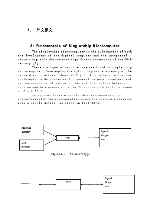
1、外文原文A: Fundamentals of Single-chip MicrocomputerTh e si ng le-c hi p m ic ro co mp ut er i s t he c ul mi na ti on of b oth t h e de ve lo pm en t o f t he d ig it al co m pu te r an d th e i n te gr at edc i rc ui t a rg ua bl y t h e to w m os t s ig ni f ic an t i nv en ti on s o f t he20th c e nt ur y [1].Th es e t ow ty pe s of ar ch it ec tu re a re fo un d i n s in g le-c hip m i cr oc om pu te r. So m e em pl oy t he spl i t pr og ra m/da ta m e mo ry o f th e H a rv ar d ar ch it ect u re, sh ow n in Fi g.3-5A-1, o th ers fo ll ow t he p h il os op hy, wi del y a da pt ed f or ge n er al-p ur po se co m pu te rs a nd m i cr op ro ce ss o r s, o f ma ki ng n o log i ca l di st in ct ion be tw ee np r og ra m an d d at a m e mo ry a s i n t he P r in ce to n ar ch ite c tu re, sh ow n i n F ig.3-5A-2.In g en er al te r ms a s in gl e-chi p m ic ro co mp ut er i sc h ar ac te ri zed b y t he i nc or po ra ti on of a ll t he un it s of a co mp ut er i n to a s in gl e d ev i ce, as s ho wn in Fi g3-5A-3.Fig.3-5A-1 A Harvard typeFig.3-5A-2. A conventional Princeton computerFig3-5A-3. Principal features of a microcomputerRead only memory (ROM).R OM i s us ua ll y f or th e p e rm an en t,n o n-vo la ti le s tor a ge o f an a pp lic a ti on s pr og ra m .M an ym i cr oc om pu te rs an d m ar e in te nd e d f or hi gh-v ol um e a p pl ic at io ns a n d he nc e t h e eco n om ic al m an uf act u re o f th e de vic e s re qu ir es t h at t he co nt en t s o f t he pr og ra m me m or y b e co mm it t ed pe rm a ne nt ly d u ri ng t he m an ufa c tu re o f ch ip s .Cl ea rl y, t hi s i m pl ie s ar i go ro us a pp ro ach to R OM c od e de ve l op me nt s in ce ch a ng es c an no t b e m ad e af te r m anu f a c tu re .Th is d ev e lo pm en t pr oc ess ma y in vo lv e e m ul at io n us in g a so ph is ti ca te d d e ve lo pm en t sy ste m w it h ah a rd wa re e mu la tio n c ap ab il it y as w el l as t he u se o f po we rf ul s o ft wa re t oo ls.So me m an uf act u re rs p ro vi de ad d it io na l RO M opt i on s byi n cl ud in g i n th eir r a n ge d ev ic es wi t h (or i nt en de d f o r u se w it h) u s er p ro gr am ma ble me mo ry. Th e sim p le st o f th es e i s u su al lyd e vi ce w hi ch c an o p er at e in a mi cro p ro ce ss or m od e b y u si ng s om e o f t he i np ut/o utp u t li ne s as a n a d dr es s an d da ta b us f ora c ce ss in g ex te rna l m em or y. T hi s t y pe o f de vi ce ca nb eh av ef u nc ti on al ly a s t h e si ng le ch ip mi cr oc om pu te r fro m w hi ch it is d e ri ve d al be it wi t h re st ri ct ed I/O a nd a m od if ied ex te rn alc i rc ui t. Th e u se o f th es ed ev ic es i s c om mo ne ve n i n pr od uc ti on c i rc ui ts wh er e t he vo lu me do es no t j us tif y t h e d ev el o pm en t c os ts o f c us to m o n-ch i p R OM[2];t he re c a n s ti ll be a s ig nif i ca nt sa vi ng i n I/O an d o th er c h ip s c om pa re d t o a co nv en ti on al mi c ro pr oc es so r b a se d ci rc ui t. Mo r e ex ac t re pl ace m en t fo r RO M dev i ce s ca n be o b ta in ed i n th e f o rm o f va ri an ts w it h 'p ig gy-b ack'E P RO M(Er as ab le pr o gr am ma bl e RO M )s oc ke ts o r d ev ic e s wi th EP RO M i n st ea d o f RO M 。
电气工程与自动化毕业论文中英文资料外文翻译
电气工程与自动化毕业论文中英文资料外文翻译The Transformer on load ﹠Introduction to DC MachinesIt has been shown that a primary input voltage 1V can be transformed to any desired open-circuit secondary voltage 2E by a suitable choice of turns ratio. 2E is available for circulating a load current impedance. For the moment, a lagging power factor will be considered. The secondary current and the resulting ampere-turns 22N I will change the flux, tending to demagnetize the core, reduce m Φ and with it 1E . Because the primary leakage impedance drop is so low, a small alteration to 1Ewill cause an appreciable increase of primary current from 0I to a new value of 1Iequal to ()()i jX R E V ++111/. The extra primary current and ampere-turns nearly cancel the whole of the secondary ampere-turns. This being so , the mutual flux suffers only a slight modification and requires practically the same net ampere-turns 10N I as on no load. The total primary ampere-turns are increased by an amount 22N I necessary to neutralize the same amount of secondary ampere-turns. In thevector equation , 102211N I N I N I =+; alternatively, 221011N I N I N I -=. At full load,the current 0I is only about 5% of the full-load current and so 1I is nearly equalto 122/N N I . Because in mind that 2121/N N E E =, the input kV A which is approximately 11I E is also approximately equal to the output kV A, 22I E .The physical current has increased, and with in the primary leakage flux towhich it is proportional. The total flux linking the primary ,111Φ=Φ+Φ=Φm p , isshown unchanged because the total back e.m.f.,(dt d N E /111Φ-)is still equal and opposite to 1V . However, there has been a redistribution of flux and the mutual component has fallen due to the increase of 1Φ with 1I . Although the change is small, the secondary demand could not be met without a mutual flux and e.m.f.alteration to permit primary current to change. The net flux s Φlinking thesecondary winding has been further reduced by the establishment of secondaryleakage flux due to 2I , and this opposes m Φ. Although m Φ and 2Φ are indicatedseparately , they combine to one resultant in the core which will be downwards at theinstant shown. Thus the secondary terminal voltage is reduced to dt d N V S /22Φ-=which can be considered in two components, i.e. dt d N dt d N V m //2222Φ-Φ-=orvectorially 2222I jX E V -=. As for the primary, 2Φ is responsible for a substantiallyconstant secondary leakage inductance222222/Λ=ΦN i N . It will be noticed that the primary leakage flux is responsible for part of the change in the secondary terminal voltage due to its effects on the mutual flux. The two leakage fluxes are closely related; 2Φ, for example, by its demagnetizing action on m Φ has caused the changes on the primary side which led to the establishment of primary leakage flux.If a low enough leading power factor is considered, the total secondary flux and the mutual flux are increased causing the secondary terminal voltage to rise with load. p Φ is unchanged in magnitude from the no load condition since, neglecting resistance, it still has to provide a total back e.m.f. equal to 1V . It is virtually the same as 11Φ, though now produced by the combined effect of primary and secondary ampere-turns. The mutual flux must still change with load to give a change of 1E and permit more primary current to flow. 1E has increased this time but due to the vector combination with 1V there is still an increase of primary current.Two more points should be made about the figures. Firstly, a unity turns ratio has been assumed for convenience so that '21E E =. Secondly, the physical picture is drawn for a different instant of time from the vector diagrams which show 0=Φm , if the horizontal axis is taken as usual, to be the zero time reference. There are instants in the cycle when primary leakage flux is zero, when the secondary leakage flux is zero, and when primary and secondary leakage flux is zero, and when primary and secondary leakage fluxes are in the same sense.The equivalent circuit already derived for the transformer with the secondary terminals open, can easily be extended to cover the loaded secondary by the addition of the secondary resistance and leakage reactance.Practically all transformers have a turns ratio different from unity although such an arrangement is sometimes employed for the purposes of electrically isolating one circuit from another operating at the same voltage. To explain the case where 21N N ≠ the reaction of the secondary will be viewed from the primary winding. The reaction is experienced only in terms of the magnetizing force due to the secondary ampere-turns. There is no way of detecting from the primary side whether 2I is large and 2N small or vice versa, it is the product of current and turns which causesthe reaction. Consequently, a secondary winding can be replaced by any number of different equivalent windings and load circuits which will give rise to an identical reaction on the primary .It is clearly convenient to change the secondary winding to an equivalent winding having the same number of turns 1N as the primary.With 2N changes to 1N , since the e.m.f.s are proportional to turns, 2212)/('E N N E = which is the same as 1E .For current, since the reaction ampere turns must be unchanged 1222'''N I N I = must be equal to 22N I .i.e. 2122)/(I N N I =.For impedance , since any secondary voltage V becomes V N N )/(21, and secondary current I becomes I N N )/(12, then any secondary impedance, including load impedance, must becomeI V N N I V /)/('/'221=. Consequently,22212)/('R N N R = and 22212)/('X N N X = . If the primary turns are taken as reference turns, the process is called referring to the primary side.There are a few checks which can be made to see if the procedure outlined is valid.For example, the copper loss in the referred secondary winding must be the same as in the original secondary otherwise the primary would have to supply a differentloss power. ''222R I must be equal to 222R I . )222122122/()/(N N R N N I •• does infact reduce to 222R I .Similarly the stored magnetic energy in the leakage field)2/1(2LI which is proportional to 22'X I will be found to check as ''22X I . The referred secondary 2212221222)/()/(''I E N N I N N E I E kVA =•==.The argument is sound, though at first it may have seemed suspect. In fact, if the actual secondary winding was removed physically from the core and replaced by the equivalent winding and load circuit designed to give the parameters 1N ,'2R ,'2X and '2I , measurements from the primary terminals would be unable to detect any difference in secondary ampere-turns, kVA demand or copper loss, under normal power frequency operation.There is no point in choosing any basis other than equal turns on primary andreferred secondary, but it is sometimes convenient to refer the primary to the secondary winding. In this case, if all the subscript 1’s are interchanged for the subscript 2’s, the necessary referring constants are easily found; e.g. 2'1R R ≈,21'X X ≈; similarly 1'2R R ≈ and 12'X X ≈.The equivalent circuit for the general case where 21N N ≠ except that m r hasbeen added to allow for iron loss and an ideal lossless transformation has been included before the secondary terminals to return '2V to 2V .All calculations of internal voltage and power losses are made before this ideal transformation is applied. The behaviour of a transformer as detected at both sets of terminals is the same as the behaviour detected at the corresponding terminals of this circuit when the appropriate parameters are inserted. The slightly different representation showing the coils 1N and 2N side by side with a core in between is only used for convenience. On the transformer itself, the coils are , of course , wound round the same core.Very little error is introduced if the magnetising branch is transferred to the primary terminals, but a few anomalies will arise. For example ,the current shown flowing through the primary impedance is no longer the whole of the primary current.The error is quite small since 0I is usually such a small fraction of 1I . Slightlydifferent answers may be obtained to a particular problem depending on whether or not allowance is made for this error. With this simplified circuit, the primary and referred secondary impedances can be added to give:221211)/(Re N N R R += and 221211)/(N N X X Xe +=It should be pointed out that the equivalent circuit as derived here is only valid for normal operation at power frequencies; capacitance effects must be taken into account whenever the rate of change of voltage would give rise to appreciablecapacitance currents, dt CdV I c /=. They are important at high voltages and atfrequencies much beyond 100 cycles/sec. A further point is not the only possible equivalent circuit even for power frequencies .An alternative , treating the transformer as a three-or four-terminal network, gives rise to a representation which is just as accurate and has some advantages for the circuit engineer who treats all devices as circuit elements with certain transfer properties. The circuit on this basiswould have a turns ratio having a phase shift as well as a magnitude change, and the impedances would not be the same as those of the windings. The circuit would not explain the phenomena within the device like the effects of saturation, so for an understanding of internal behaviour .There are two ways of looking at the equivalent circuit:(a) viewed from the primary as a sink but the referred load impedance connected across '2V ,or(b) viewed from the secondary as a source of constant voltage 1V with internal drops due to 1Re and 1Xe . The magnetizing branch is sometimes omitted in this representation and so the circuit reduces to a generator producing a constant voltage 1E (actually equal to 1V ) and having an internal impedance jX R + (actually equal to 11Re jXe +).In either case, the parameters could be referred to the secondary winding and this may save calculation time .The resistances and reactances can be obtained from two simple light load tests. Introduction to DC MachinesDC machines are characterized by their versatility. By means of various combination of shunt, series, and separately excited field windings they can be designed to display a wide variety of volt-ampere or speed-torque characteristics for both dynamic and steadystate operation. Because of the ease with which they can be controlled , systems of DC machines are often used in applications requiring a wide range of motor speeds or precise control of motor output.The essential features of a DC machine are shown schematically. The stator has salient poles and is excited by one or more field coils. The air-gap flux distribution created by the field winding is symmetrical about the centerline of the field poles. This axis is called the field axis or direct axis.As we know , the AC voltage generated in each rotating armature coil is converted to DC in the external armature terminals by means of a rotating commutator and stationary brushes to which the armature leads are connected. The commutator-brush combination forms a mechanical rectifier, resulting in a DCarmature voltage as well as an armature m.m.f. wave which is fixed in space. The brushes are located so that commutation occurs when the coil sides are in the neutral zone , midway between the field poles. The axis of the armature m.m.f. wave then in 90 electrical degrees from the axis of the field poles, i.e., in the quadrature axis. In the schematic representation the brushes are shown in quarature axis because this is the position of the coils to which they are connected. The armature m.m.f. wave then is along the brush axis as shown.. (The geometrical position of the brushes in an actual machine is approximately 90 electrical degrees from their position in the schematic diagram because of the shape of the end connections to the commutator.)The magnetic torque and the speed voltage appearing at the brushes are independent of the spatial waveform of the flux distribution; for convenience we shall continue to assume a sinusoidal flux-density wave in the air gap. The torque can then be found from the magnetic field viewpoint.The torque can be expressed in terms of the interaction of the direct-axis air-gapflux per pole d Φ and the space-fundamental component 1a F of the armature m.m.f.wave . With the brushes in the quadrature axis, the angle between these fields is 90 electrical degrees, and its sine equals unity. For a P pole machine 12)2(2a d F P T ϕπ=In which the minus sign has been dropped because the positive direction of thetorque can be determined from physical reasoning. The space fundamental 1a F ofthe sawtooth armature m.m.f. wave is 8/2π times its peak. Substitution in above equation then givesa d a a d a i K i m PC T ϕϕπ==2 Where a i =current in external armature circuit;a C =total number of conductors in armature winding;m =number of parallel paths through winding;Andm PC K aa π2=Is a constant fixed by the design of the winding.The rectified voltage generated in the armature has already been discussedbefore for an elementary single-coil armature. The effect of distributing the winding in several slots is shown in figure ,in which each of the rectified sine waves is the voltage generated in one of the coils, commutation taking place at the moment when the coil sides are in the neutral zone. The generated voltage as observed from the brushes is the sum of the rectified voltages of all the coils in series between brushesand is shown by the rippling line labeled a e in figure. With a dozen or socommutator segments per pole, the ripple becomes very small and the average generated voltage observed from the brushes equals the sum of the average values ofthe rectified coil voltages. The rectified voltage a e between brushes, known also asthe speed voltage, ism d a m d a a W K W m PC e ϕϕπ==2 Where a K is the design constant. The rectified voltage of a distributed winding has the same average value as that of a concentrated coil. The difference is that the ripple is greatly reduced.From the above equations, with all variable expressed in SI units:m a a Tw i e =This equation simply says that the instantaneous electric power associated with the speed voltage equals the instantaneous mechanical power associated with the magnetic torque , the direction of power flow being determined by whether the machine is acting as a motor or generator.The direct-axis air-gap flux is produced by the combined m.m.f. f f i N ∑ of the field windings, the flux-m.m.f. characteristic being the magnetization curve for the particular iron geometry of the machine. In the magnetization curve, it is assumed that the armature m.m.f. wave is perpendicular to the field axis. It will be necessary to reexamine this assumption later in this chapter, where the effects of saturation are investigated more thoroughly. Because the armature e.m.f. is proportional to flux times speed, it is usually more convenient to express the magnetization curve in termsof the armature e.m.f. 0a e at a constant speed 0m w . The voltage a e for a given fluxat any other speed m w is proportional to the speed,i.e. 00a m m a e w w e =Figure shows the magnetization curve with only one field winding excited. This curve can easily be obtained by test methods, no knowledge of any design details being required.Over a fairly wide range of excitation the reluctance of the iron is negligible compared with that of the air gap. In this region the flux is linearly proportional to the total m.m.f. of the field windings, the constant of proportionality being the direct-axis air-gap permeance.The outstanding advantages of DC machines arise from the wide variety of operating characteristics which can be obtained by selection of the method of excitation of the field windings. The field windings may be separately excited from an external DC source, or they may be self-excited; i.e., the machine may supply its own excitation. The method of excitation profoundly influences not only the steady-state characteristics, but also the dynamic behavior of the machine in control systems.The connection diagram of a separately excited generator is given. The required field current is a very small fraction of the rated armature current. A small amount of power in the field circuit may control a relatively large amount of power in the armature circuit; i.e., the generator is a power amplifier. Separately excited generators are often used in feedback control systems when control of the armature voltage over a wide range is required. The field windings of self-excited generators may be supplied in three different ways. The field may be connected in series with the armature, resulting in a shunt generator, or the field may be in two sections, one of which is connected in series and the other in shunt with the armature, resulting in a compound generator. With self-excited generators residual magnetism must be present in the machine iron to get the self-excitation process started.In the typical steady-state volt-ampere characteristics, constant-speed primemovers being assumed. The relation between the steady-state generated e.m.f. a Eand the terminal voltage t V isa a a t R I E V -=Where a I is the armature current output and a R is the armature circuitresistance. In a generator, a E is large than t V ; and the electromagnetic torque T is acountertorque opposing rotation.The terminal voltage of a separately excited generator decreases slightly with increase in the load current, principally because of the voltage drop in the armature resistance. The field current of a series generator is the same as the load current, so that the air-gap flux and hence the voltage vary widely with load. As a consequence, series generators are not often used. The voltage of shunt generators drops off somewhat with load. Compound generators are normally connected so that the m.m.f. of the series winding aids that of the shunt winding. The advantage is that through the action of the series winding the flux per pole can increase with load, resulting in a voltage output which is nearly constant. Usually, shunt winding contains many turns of comparatively heavy conductor because it must carry the full armature current of the machine. The voltage of both shunt and compound generators can be controlled over reasonable limits by means of rheostats in the shunt field. Any of the methods of excitation used for generators can also be used for motors. In the typical steady-state speed-torque characteristics, it is assumed that the motor terminals are supplied froma constant-voltage source. In a motor the relation between the e.m.f. a E generated inthe armature and the terminal voltage t V isa a a t R I E V +=Where a I is now the armature current input. The generated e.m.f. a E is nowsmaller than the terminal voltage t V , the armature current is in the oppositedirection to that in a motor, and the electromagnetic torque is in the direction to sustain rotation of the armature.In shunt and separately excited motors the field flux is nearly constant. Consequently, increased torque must be accompanied by a very nearly proportional increase in armature current and hence by a small decrease in counter e.m.f. to allow this increased current through the small armature resistance. Since counter e.m.f. is determined by flux and speed, the speed must drop slightly. Like the squirrel-cage induction motor ,the shunt motor is substantially a constant-speed motor having about 5 percent drop in speed from no load to full load. Starting torque and maximum torque are limited by the armature current that can be commutatedsuccessfully.An outstanding advantage of the shunt motor is ease of speed control. With a rheostat in the shunt-field circuit, the field current and flux per pole can be varied at will, and variation of flux causes the inverse variation of speed to maintain counter e.m.f. approximately equal to the impressed terminal voltage. A maximum speed range of about 4 or 5 to 1 can be obtained by this method, the limitation again being commutating conditions. By variation of the impressed armature voltage, very wide speed ranges can be obtained.In the series motor, increase in load is accompanied by increase in the armature current and m.m.f. and the stator field flux (provided the iron is not completely saturated). Because flux increases with load, speed must drop in order to maintain the balance between impressed voltage and counter e.m.f.; moreover, the increase in armature current caused by increased torque is smaller than in the shunt motor because of the increased flux. The series motor is therefore a varying-speed motor with a markedly drooping speed-load characteristic. For applications requiring heavy torque overloads, this characteristic is particularly advantageous because the corresponding power overloads are held to more reasonable values by the associated speed drops. Very favorable starting characteristics also result from the increase in flux with increased armature current.In the compound motor the series field may be connected either cumulatively, so that its.m.m.f.adds to that of the shunt field, or differentially, so that it opposes. The differential connection is very rarely used. A cumulatively compounded motor has speed-load characteristic intermediate between those of a shunt and a series motor, the drop of speed with load depending on the relative number of ampere-turns in the shunt and series fields. It does not have the disadvantage of very high light-load speed associated with a series motor, but it retains to a considerable degree the advantages of series excitation.The application advantages of DC machines lie in the variety of performance characteristics offered by the possibilities of shunt, series, and compound excitation. Some of these characteristics have been touched upon briefly in this article. Stillgreater possibilities exist if additional sets of brushes are added so that other voltages can be obtained from the commutator. Thus the versatility of DC machine systems and their adaptability to control, both manual and automatic, are their outstanding features.中文翻译负载运行的变压器及直流电机导论通过选择合适的匝数比,一次侧输入电压1V 可任意转换成所希望的二次侧开路电压2E 。
电气工程及其自动化专业 外文文献 英文文献 外文翻译 plc方面

1、外文原文(复印件)A: Fundamentals of Single-chip MicrocomputerTh e si ng le-ch i p mi cr oc om pu ter is t he c ul mi nat i on o f bo th t h e d ev el op me nt o f th e d ig it al com p ut er an d t he int e gr at ed ci rc ui ta r gu ab ly th e t ow m os t s i gn if ic ant i nv en ti on s o f t h e 20t h c en tu ry[1].Th es e to w typ e s of a rc hi te ctu r e ar e fo un d i n s in gl e-ch ip m i cr oc om pu te r. So m e em pl oy t he sp l it p ro gr am/d ata me mo ry o f th e H a rv ar d ar ch it ect u re, sh ow n i n -5A, ot he rs fo ll ow th e ph i lo so ph y, w i de ly a da pt ed fo r g en er al-p ur pos e c om pu te rs an d m i cr op ro ce ss or s, o f m a ki ng no lo gi c al di st in ct io n b e tw ee n p ro gr am a n d da t a m em ory a s i n th e Pr in cet o n ar ch it ec tu re,sh ow n in-5A.In g en er al te r ms a s in gl e-chi p m ic ro co mp ut er i sc h ar ac te ri zed b y the i nc or po ra tio n of al l t he uni t s o f a co mp ut er i n to a s in gl e dev i ce, as s ho wn in Fi g3-5A-3.-5A-1 A Harvard type-5A. A conventional Princeton computerFig3-5A-3. Principal features of a microcomputerRead only memory (ROM).R OM i s u su al ly f or th e p er ma ne nt, n o n-vo la ti le s tor a ge o f an a pp lic a ti on s pr og ra m .M an ym i cr oc om pu te rs an d mi cr oc on tr ol le r s a re in t en de d fo r h ig h-v ol ume a p pl ic at io ns a nd h en ce t he e co nom i ca l ma nu fa ct ure of t he d ev ic es r e qu ir es t ha t the co nt en ts o f the pr og ra m me mo ry b e co mm it te dp e rm an en tl y d ur in g th e m an uf ac tu re o f c hi ps . Cl ear l y, th is im pl ie sa ri g or ou s a pp roa c h t o R OM co de d e ve lo pm en t s in ce c ha ng es ca nn otb e m ad e af te r man u fa ct ur e .T hi s d e ve lo pm en t pr oce s s ma y in vo lv e e m ul at io n us in g a s op hi st ic at ed deve lo pm en t sy st em w i th a ha rd wa re e m ul at io n ca pa bil i ty a s we ll a s th e u se of po we rf ul so ft wa re t oo ls.So me m an uf act u re rs p ro vi de ad d it io na l RO M opt i on s byi n cl ud in g i n th ei r ra ng e de vi ce s wi th (or i nt en de d fo r us e wi th) u s er pr og ra mm ab le m em or y. Th e s im p le st of th es e i s us ua ll y d ev ice w h ic h ca n op er ate in a m ic ro pr oce s so r mo de b y usi n g so me o f th e i n pu t/ou tp ut li ne s as a n ad dr es s an d da ta b us f or acc e ss in g e xt er na l m e mo ry. T hi s t ype o f d ev ic e c an b e ha ve fu nc ti on al l y a s t he si ng le c h ip mi cr oc om pu te r fr om wh ic h i t i s de ri ve d a lb eit w it h r es tr ic ted I/O an d a mo di fie d e xt er na l ci rcu i t. T he u se o f t h es e RO Ml es sd e vi ce s is c om mo n e ve n in p ro du ct io n c ir cu it s wh er e t he v ol um e do es n o t ju st if y th e d e ve lo pm en t co sts of c us to m on-ch i p RO M[2];t he re c a n st il l b e a si g ni fi ca nt s a vi ng in I/O a nd ot he r c hi ps co mp ar ed t o a c on ve nt io nal mi cr op ro ce ss or b as ed c ir cu it. M o re e xa ctr e pl ac em en t fo r RO M d ev ic es c an b e o bt ai ne d in t he f o rm o f va ri an ts w i th 'pi gg y-ba ck'EP RO M(Er as ab le p ro gr am ma bl e ROM)s oc ke ts o rd e vi ce s w it h EP ROM i ns te ad o f R OM 。
(完整版)PLC英文文献+翻译

自动化专业本科毕业设计英文翻译学院(部):专业班级:学生姓名:指导教师:年月日Programmable Logic ControllerONE:PLC overviewProgrammable controller is the first in the late 1960s in the United States, then called PLC programmable logic controller (Programmable Logic Controller) is used to replace relays. For the implementation of the logical judgment, timing, sequence number, and other control functions. The concept is presented PLC General Motors Corporation. PLC and the basic design is the computer functional improvements, flexible, generic and other advantages and relay control system simple and easy to operate, such as the advantages of cheap prices combined controller hardware is standard and overall. According to the practical application of target software in order to control the content of the user procedures memory controller, the controller and connecting the accused convenient target.In the mid-1970s, the PLC has been widely used as a central processing unit microprocessor, import export module and the external circuits are used, large-scale integrated circuits even when the Plc is no longer the only logical (IC) judgment functions also have data processing, PID conditioning and data communications functions. International Electro technical Commission (IEC) standards promulgated programmable controller for programmable controller draft made the following definition : programmable controller is a digital electronic computers operating system, specifically for applications in the industrial design environment. It used programmable memory, used to implement logic in their internal storage operations, sequence control, timing, counting and arithmetic operations, such as operating instructions, and through digital and analog input and output, the control of various types of machinery or production processes. Programmable controller and related peripherals, and industrial control systems easily linked to form a whole, to expand its functional design. Programmable controller for the user, is a non-contact equipment, the procedures can be changed to change production processes. The programmable controller has become a powerful tool for factory automation, widely popular replication.Programmable controller is user-oriented industries dedicated control computer, with many distinctive features.First, high reliability, anti-interference capability;Second,programming visual, simple;Third, adaptability good;Fourth functional improvements, strong functional interface. TWO:History of PLCProgrammable Logic Controllers (PLC), a computing device invented by Richard E. Morley in 1968, have been widely used in industry including manufacturing systems, transportation systems, chemical process facilities, and many others. At that time, the PLC replaced the hardwired logic with soft-wired logic or so-called relay ladder logic (RLL), a programming language visually resembling the hardwired logic, and reduced thereby the configuration time from 6 months down to 6 days [Moody and Morley, 1999].Although PC based control has started to come into place, PLC based control will remain the technique to which the majority of industrial applications will adhere due to its higher performance, lower price, and superior reliability in harsh environments. Moreover, according to a study on the PLC market of Frost and Sullivan [1995], an increase of the annual sales volume to 15 million PLC per year with the hardware value of more than 8 billion US dollars has been predicted, though the prices of computing hardware is steadily dropping. The inventor of the PLC, Richard E Morley, fairly considers the PLC market as a 5-billion industry at the present time.Though PLCs are widely used in industrial practice, the programming of PLC based control systems is still very much relying on trial-and-error. Alike software engineering, PLC software design is facing the software dilemma or crisis in a similar way. Morley himself emphasized this aspect most forcefully by indicatingIf houses were built like software projects, a single woodpecker could d estroy civilization.”Particularly, practical problems in PLC programming are to eliminate software bugs and to reduce the maintenance costs of old ladderlogic programs. Though the hardware costs of PLC are dropping continuously, reducing the scan time of the ladder logic is still an issue in industry so that low-cost PLC can be used.In general, the productivity in generating PLC is far behind compared to other domains, for instance, VLSI design, where efficient computer aided design tools are in practice. Existent software engineering methodologies are not necessarily applicable to the PLC based software design because PLC-programming requires a simultaneous consideration of hardware and software. The software design becomes, thereby, more and more the major cost driver. In many industrial design projects, more than of the manpower allocated for the control system design and installation is scheduled for testing and debugging PLC programs.In addition, current PLC based control systems are not properly designed to support the growing demand for flexibility and reconfigurability of manufacturing systems. A further problem, impelling the need for a systematic design methodology, is the increasing software complexity in large-scale projects.The objective of this thesis is to develop a systematic software design methodology for PLC operated automation systems. The design methodology involves high-level description based on state transition models that treat automation control systems as discrete event systems, a stepwise design process, and set of design rules providing guidance and measurements to achieve a successful design. The tangible outcome of this research is to find a way to reduce the uncertainty in managing the control software development process, that is, reducing programming and debugging time and their variation, increasing flexibility of the automation systems, and enabling software reusability through modularity. The goal is to overcome shortcomings of current programming strategies that are based on the experience of the individual software developer. Three:now of PLCFrom the structure is divided into fixed PLC and Module PLC, the two kinds of PLC including CPU board, I/O board, display panel, memory block, power, these elements into a do not remove overall. Module type PLC including CPU module, I/O modules, memory, thepower modules, bottom or a frame, these modules can be according to certain rules combination configuration.In the user view, a detailed analysis of the CPU's internal unnecessary, but working mechanism of every part of the circuit. The CPU control works, by it reads CPU instruction, interprets the instruction and executes instructions. But the pace of work by shock signal control.Unit work under the controller command used in a digital or logic operations.In computing and storage register of computation result, it is also among the controller command and work. CPU speed and memory capacity is the important parameters fot PLC . its determines the PLC speed of work, IO PLC number and software capacity, so limits to control size.Central Processing Unit (CPU) is the brain of a PLC controller. CPU itself is usually one of the microcontrollers. Aforetime these were 8-bit microcontrollers such as 8051, and now these are 16-and 32-bit microcontrollers. Unspoken rule is that you’ll find mostly Hitachi and Fujicu microcontrollers in PLC controllers by Japanese makers, Siemens in European controllers, and Motorola microcontrollers in American ones. CPU also takes care of communication, interconnectedness among other parts of PLC controllers, program execution, memory operation, overseeing input and setting up of an output.System memory (today mostly implemented in FLASH technology) is used by a PLC for a process control system. Aside form. this operating system it also contains a user program translated foram ladder diagram to a binary form. FLASH memory contents can be changed only in case where user program is being changed. PLC controllers were used earlier instead of PLASH memory and have had EPROM memory instead of FLASH memory which had to be erased with UV lamp and programmed on programmers. With the use of FLASH technology this process was greatly shortened. Reprogramming a program memory is done through a serial cable in a program for application development.User memory is divided into blocks having special functions. Some parts of a memory are used for storing input and output status. The real status of an input is stored either as “1”or as “0”in a specific memory bit/each input or output has one corresponding bit in memory. Other parts of memory are used to store variable contents for variables used in used program. For example, time value, or counter value would be stored in this part of the memory.PLC controller can be reprogrammed through a computer (usual way), but also through manual programmers (consoles). This practically means that each PLC controller can programmed through a computer if you have the software needed for programming. Today’s transmission computers are ideal for reprogramming a PLC controller in factory itself. This is of great importance to industry. Once the system is corrected, it is also important to read the right program into a PLC again. It is also good to check from time to time whether program in a PLC has not changed. This helps to avoid hazardous situations in factory rooms (some automakers have established communication networks which regularly check programs in PLC controllers to ensure execution only of good programs).Almost every program for programming a PLC controller possesses various useful options such as: forced switching on and off of the system input/outputs (I/O lines), program follow up in real time as well as documenting a diagram. This documenting is necessary to understand and define failures and malfunctions. Programmer can add remarks, names of input or output devices, and comments that can be useful when finding errors, or with system maintenance. Adding comments and remarks enables any technician (and not just a person who developed the system) to understand a ladder diagram right away. Comments and remarks can even quote precisely part numbers if replacements would be needed. This would speed up a repair of any problems that come up due to bad parts. The old way was such that a person who developed a system had protection on the program, so nobody aside from this person could understand how it was done. Correctly documented ladder diagram allows any technician to understand thoroughly how system functions.Electrical supply is used in bringing electrical energy to central processing unit. Most PLC controllers work either at 24 VDC or 220V AC. On some PLC controllers you’ll find electrical supply as a separatemodule. Those are usually bigger PLC controllers, while small and medium series already contain the supply module. User has to determine how much current to take from I/O module to ensure that electrical supply provides appropriate amount of current. Different types of modules use different amounts of electrical current.This electrical supply is usually not used to start external input or output. User has to provide separate supplies in starting PLC controller inputs because then you can ensure so called “pure” supply for the PLC controller. With pure supply we mean supply where industrial environment can not affect it damagingly. Some of the smaller PLC controllers supply their inputs with voltage from a small supply source already incorporated into a PLC.Four:PLC design criteriaA systematic approach to designing PLC software can overcome deficiencies in the traditional way of programming manufacturing control systems, and can have wide ramifications in several industrial applications. Automation control systems are modeled by formal languages or, equivalently, by state machines. Formal representations provide a high-level description of the behavior of the system to be controlled. State machines can be analytically evaluated as to whether or not they meet the desired goals. Secondly, a state machine description provides a structured representation to convey the logical requirements and constraints such as detailed safety rules. Thirdly, well-defined control systems design outcomes are conducive to automatic code generation- An ability to produce control software executable on commercial distinct logic controllers can reduce programming lead-time and labor cost. In particular, the thesis is relevant with respect to the following aspects.In modern manufacturing, systems are characterized by product and process innovation, become customer-driven and thus have to respond quickly to changing system requirements. A major challenge is therefore to provide enabling technologies that can economically reconfigure automation control systems in response to changing needs and new opportunities. Design and operational knowledge can be reused inreal-time, therefore, giving a significant competitive edge in industrial practice.Studies have shown that programming methodologies in automation systems have not been able to match rapid increase in use of computing resources. For instance, the programming of PLC still relies on a conventional programming style with ladder logic diagrams. As a result, the delays and resources in programming are a major stumbling stone for the progress of manufacturing industry. Testing and debugging may consume over 50% of the manpower allocated for the PLC program design. Standards [IEC 60848, 1999; IEC-61131-3, 1993; IEC 61499, 1998; ISO 15745-1, 1999] have been formed to fix and disseminate state-of-the-art design methods, but they normally cannot participate in advancing the knowledge of efficient program and system design.A systematic approach will increase the level of design automation through reusing existing software components, and will provide methods to make large-scale system design manageable. Likewise, it will improve software quality and reliability and will be relevant to systems high security standards, especially those having hazardous impact on the environment such as airport control, and public railroads.The software industry is regarded as a performance destructor and complexity generator. Steadily shrinking hardware prices spoils the need for software performance in terms of code optimization and efficiency. The result is that massive and less efficient software code on one hand outpaces the gains in hardware performance on the other hand. Secondly, software proliferates into complexity of unmanageable dimensions; software redesign and maintenance-essential in modern automation systems-becomes nearly impossible. Particularly, PLC programs have evolved from a couple lines of code 25 years ago to thousands of lines of code with a similar number of 1/O points. Increased safety, for instance new policies on fire protection, and the flexibility of modern automation systems add complexity to the program design process. Consequently, the life-cycle cost of software is a permanently growing fraction of the total cost. 80-90% of these costs are going into software maintenance, debugging, adaptation and expansion to meet changing needs.Today, the primary focus of most design research is based on mechanical or electrical products. One of the by-products of this proposed research is to enhance our fundamental understanding of design theory and methodology by extending it to the field of engineering systems design. A system design theory for large-scale and complex system is not yet fully developed. Particularly, the question of how to simplify a complicated or complex design task has not been tackled in a scientific way. Furthermore, building a bridge between design theory and the latest epistemological outcomes of formal representations in computer sciences and operations research, such as discrete event system modeling, can advance future development in engineering design.From a logical perspective, PLC software design is similar to the hardware design of integrated circuits. Modern VLSI designs are extremely complex with several million parts and a product development time of 3 years [Whitney, 1996]. The design process is normally separated into a component design and a system design stage. At component design stage, single functions are designed and verified. At system design stage, components are aggregated and the whole system behavior and functionality is tested through simulation. In general, a complete verification is impossible. Hence, a systematic approach as exemplified for the PLC program design may impact the logical hardware design.可编程控制器一、PLC概述可编程控制器是60年代末在美国首先出现的,当时叫可编程逻辑控制器PLC(Programmable Logic Controller),目的是用来取代继电器。
电气 自动化 外文文献 外文翻译 英文文献
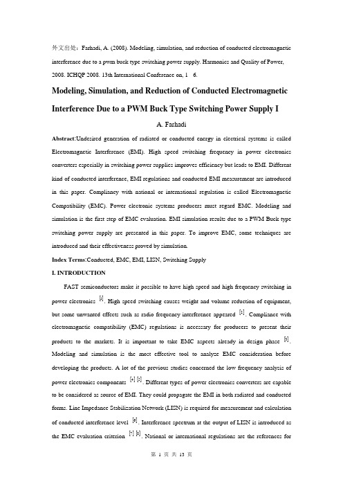
外文出处:Farhadi, A. (2008). Modeling, simulation, and reduction of conducted electromagnetic interference due to a pwm buck type switching power supply. Harmonics and Quality of Power, 2008. ICHQP 2008. 13th International Conference on, 1 - 6.Modeling, Simulation, and Reduction of Conducted Electromagnetic Interference Due to a PWM Buck Type Switching Power Supply IA. FarhadiAbstract:Undesired generation of radiated or conducted energy in electrical systems is called Electromagnetic Interference (EMI). High speed switching frequency in power electronics converters especially in switching power supplies improves efficiency but leads to EMI. Different kind of conducted interference, EMI regulations and conducted EMI measurement are introduced in this paper. Compliancy with national or international regulation is called Electromagnetic Compatibility (EMC). Power electronic systems producers must regard EMC. Modeling and simulation is the first step of EMC evaluation. EMI simulation results due to a PWM Buck type switching power supply are presented in this paper. To improve EMC, some techniques are introduced and their effectiveness proved by simulation.Index Terms:Conducted, EMC, EMI, LISN, Switching SupplyI. INTRODUCTIONFAST semiconductors make it possible to have high speed and high frequency switching in power electronics []1. High speed switching causes weight and volume reduction of equipment, but some unwanted effects such as radio frequency interference appeared []2. Compliance with electromagnetic compatibility (EMC) regulations is necessary for producers to present their products to the markets. It is important to take EMC aspects already in design phase []3. Modeling and simulation is the most effective tool to analyze EMC consideration before developing the products. A lot of the previous studies concerned the low frequency analysis of power electronics components []4[]5. Different types of power electronics converters are capable to be considered as source of EMI. They could propagate the EMI in both radiated and conducted forms. Line Impedance Stabilization Network (LISN) is required for measurement and calculation of conducted interference level []6. Interference spectrum at the output of LISN is introduced as the EMC evaluation criterion []7[]8. National or international regulations are the references forthe evaluation of equipment in point of view of EMC []7[]8.II. SOURCE, PATH AND VICTIM OF EMIUndesired voltage or current is called interference and their cause is called interference source. In this paper a high-speed switching power supply is the source of interference.Interference propagated by radiation in area around of an interference source or by conduction through common cabling or wiring connections. In this study conducted emission is considered only. Equipment such as computers, receivers, amplifiers, industrial controllers, etc that are exposed to interference corruption are called victims. The common connections of elements, source lines and cabling provide paths for conducted noise or interference. Electromagnetic conducted interference has two components as differential mode and common mode []9.A. Differential mode conducted interferenceThis mode is related to the noise that is imposed between different lines of a test circuit by a noise source. Related current path is shown in Fig. 1 []9. The interference source, path impedances, differential mode current and load impedance are also shown in Fig. 1.B. Common mode conducted interferenceCommon mode noise or interference could appear and impose between the lines, cables or connections and common ground. Any leakage current between load and common ground couldbe modeled by interference voltage source.Fig. 2 demonstrates the common mode interference source, common mode currents Iandcm1 and the related current paths[]9.The power electronics converters perform as noise source Icm2between lines of the supply network. In this study differential mode of conducted interference is particularly important and discussion will be continued considering this mode only.III. ELECTROMAGNETIC COMPATIBILITY REGULATIONS Application of electrical equipment especially static power electronic converters in different equipment is increasing more and more. As mentioned before, power electronics converters are considered as an important source of electromagnetic interference and have corrupting effects on the electric networks []2. High level of pollution resulting from various disturbances reduces the quality of power in electric networks. On the other side some residential, commercial and especially medical consumers are so sensitive to power system disturbances including voltage and frequency variations. The best solution to reduce corruption and improve power quality is complying national or international EMC regulations. CISPR, IEC, FCC and VDE are among the most famous organizations from Europe, USA and Germany who are responsible for determining and publishing the most important EMC regulations. IEC and VDE requirement and limitations on conducted emission are shown in Fig. 3 and Fig. 4 []7[]9.For different groups of consumers different classes of regulations could be complied. Class Afor common consumers and class B with more hard limitations for special consumers are separated in Fig. 3 and Fig. 4. Frequency range of limitation is different for IEC and VDE that are 150 kHz up to 30 MHz and 10 kHz up to 30 MHz respectively. Compliance of regulations is evaluated by comparison of measured or calculated conducted interference level in the mentioned frequency range with the stated requirements in regulations. In united European community compliance of regulation is mandatory and products must have certified label to show covering of requirements []8.IV. ELECTROMAGNETIC CONDUCTED INTERFERENCE MEASUREMENTA. Line Impedance Stabilization Network (LISN)1-Providing a low impedance path to transfer power from source to power electronics converter and load.2-Providing a low impedance path from interference source, here power electronics converter, to measurement port.Variation of LISN impedance versus frequency with the mentioned topology is presented inFig. 7. LISN has stabilized impedance in the range of conducted EMI measurement []7.Variation of level of signal at the output of LISN versus frequency is the spectrum of interference. The electromagnetic compatibility of a system can be evaluated by comparison of its interference spectrum with the standard limitations. The level of signal at the output of LISN in frequency range 10 kHz up to 30 MHz or 150 kHz up to 30 MHz is criterion of compatibility and should be under the standard limitations. In practical situations, the LISN output is connected to a spectrum analyzer and interference measurement is carried out. But for modeling and simulation purposes, the LISN output spectrum is calculated using appropriate software.基于压降型PWM开关电源的建模、仿真和减少传导性电磁干扰摘要:电子设备之中杂乱的辐射或者能量叫做电磁干扰(EMI)。
PLC的发展方向外文文献翻译、中英文翻译

外文资料The development direction of PLC:One is the development of the PLC operation in the direction of simplification.At present, one of the difficulties of PLC popularization is that the complicated programming makes the user prohibitive, and all programming languages of PLC are not the same in different manufacturers. Users often need to master more programming languages, which are difficult to control. Pid control, network communication, and so on. The programming and application of high speed counter, position control, data recording, formula and text display are also the difficulties in PLC programming. When programming them with common methods, we need to be familiar with the meaning of the special memory. They are assigned values at programming time and are accessed by the runtime to achieve corresponding functions. These programs also tend to have to do with interruptions. The process is cumbersome and error-prone, which hinders the further application of PLC. The development of PLC is bound to simplify the programming of complex tasks. At this point, Siemens acts as the forerunner, and only needs to input some parameters in the dialog box. Automatic generation of user programs, including interrupt programs, greatly facilitate the use of users.Second, PLC to high performance miniaturization direction development.PLC's function is getting richer and richer, and the volume is getting smaller and smaller. For example, Mitsubishi's FX-IS series PLC, the smallest type of machine, is only 60 × 90 × 75mm in volume, equivalent to a relay, but it has the ability to count at high speed, slope, alternate output and 16-bit four-bit operation, etc. It also has the adjustable potentiometer time setting function. PLC is no longer the early product that can only perform the logic operation of the switch quantity, but it has more and more powerful analog processing ability. And other advanced processing capabilities that used to be available only on computers, such as floating-point operations such as pid control, temperature control, precision Positioning, step drive, report statistics and so on. In this sense, the difference between PLC system and DCS (distributed Controlsystem) is becoming smaller and smaller. A process control system can also be constructed by using PLC.Third, the development of PLC network technology.There are two trends: on the one hand, the PLC network system is no longer a self-contained system, but is rapidly developing to an open system. In addition to forming its own characteristic PLC network system, the major brand PLC can also connect with the upper computer management system to achieve information communication and become a whole. Part of the information management system; on the other hand, field bus technology is widely used, PLC and other intelligent equipment installed on the site, such as intelligent instruments, sensors, intelligent solenoid valves, intelligent drive actuators, and so on, through a transmission medium (like twisted pair) Wires, coaxial cables, optical cables) link together and transmit information to each other according to the same communication protocol, thus forming a field network, which is more flexible in configuration, more convenient in expansion, and cheaper in cost than the simple PLC remote network. Performance price ratio is better, also more open meaning.Fourth, embedded PLC has a great space for development.The development of embedded PLC is diversified and has good performance at home and abroad: the netPLC, which combines fieldbus technology and PLC technology, introduced by Heuxun, Germany, has its own characteristics; A few years ago in China, Huazhong University of Science and Technology loaded embedded PLC system software into the EASYCORE1.00 core chipset as a hardware platform. The embedded PLC with multi-mode human channel is developed, and another development path is to develop the hardware / software integration of PLC and man-machine interface, which makes full use of case tools. Combined with the development platform and input of all kinds of embedded chips The hardware circuit library of the output channel is specially designed for developing customized PLC with ODM property for electromechanical equipment.The development space of embedded PLC in our country lies in the fact that it is very helpful to bring into full play the two characteristics of the development of automation industry in our country: there is a very strong market foundation for supporting electromechanical equipment, and it has enough, The best design and development team in the world. We can replace the universal PLC with the lowest cost, higher quality and custom-made design and production of embedded PLC.At the same time, the hardware, software, man-machine interface, communication and other aspects of embedded PLC function design is flexible, easy to cut, more close to the requirements of various grades of mechanical and electrical equipment. Embedded PLC is completely based on the technical foundation of embedded system. It can be used as .SOC chip, embedded operating system and programming environment that accords with EC61131-3 programming language standard, which makes it easy to find in the market.中文译文PLC的发展方向:一是PLC操作向简易化方向发展。
电气工程的外文文献(及翻译)
电气工程的外文文献(及翻译)文献一:Electric power consumption prediction model based on grey theory optimized by genetic algorithms本文介绍了一种基于混合灰色理论与遗传算法优化的电力消耗预测模型。
该模型使用时间序列数据来建立模型,并使用灰色理论来解决数据的不确定性问题。
通过遗传算法的优化,模型能够更好地预测电力消耗,并取得了优异的预测结果。
此模型可以在大规模电力网络中使用,并具有较高的可行性和可靠性。
文献二:Intelligent control for energy-efficient operation of electric motors本文研究了一种智能控制方法,用于电动机的节能运行。
该方法提供了一种更高效的控制策略,使电动机能够在不同负载条件下以较低的功率运行。
该智能控制使用模糊逻辑方法来确定最佳的控制参数,并使用遗传算法来优化参数。
实验结果表明,该智能控制方法可以显著降低电动机的能耗,节省电能。
文献三:Fault diagnosis system for power transformers based on dissolved gas analysis本文介绍了一种基于溶解气体分析的电力变压器故障诊断系统。
通过对变压器油中的气体样品进行分析,可以检测和诊断变压器内部存在的故障类型。
该系统使用人工神经网络模型来对气体分析数据进行处理和分类。
实验结果表明,该系统可以准确地检测和诊断变压器的故障,并有助于实现有效的维护和管理。
文献四:Power quality improvement using series active filter based on iterative learning control technique本文研究了一种基于迭代研究控制技术的串联有源滤波器用于电能质量改善的方法。
- 1、下载文档前请自行甄别文档内容的完整性,平台不提供额外的编辑、内容补充、找答案等附加服务。
- 2、"仅部分预览"的文档,不可在线预览部分如存在完整性等问题,可反馈申请退款(可完整预览的文档不适用该条件!)。
- 3、如文档侵犯您的权益,请联系客服反馈,我们会尽快为您处理(人工客服工作时间:9:00-18:30)。
1、外文原文A: Fundamentals of Single-chip MicrocomputerTh e si ng le-c hi p m ic ro co mp ut er i s t he c ul mi na ti on of b oth t h e de ve lo pm en t o f t he d ig it al co m pu te r an d th e i n te gr at edc i rc ui t a rg ua bl y t h e to w m os t s ig ni f ic an t i nv en ti on s o f t he20th c e nt ur y [1].Th es e t ow ty pe s of ar ch it ec tu re a re fo un d i n s in g le-c hip m i cr oc om pu te r. So m e em pl oy t he spl i t pr og ra m/da ta m e mo ry o f th e H a rv ar d ar ch it ect u re, sh ow n in Fi g.3-5A-1, o th ers fo ll ow t he p h il os op hy, wi del y a da pt ed f or ge n er al-p ur po se co m pu te rs a nd m i cr op ro ce ss o r s, o f ma ki ng n o log i ca l di st in ct ion be tw ee np r og ra m an d d at a m e mo ry a s i n t he P r in ce to n ar ch ite c tu re, sh ow n i n F ig.3-5A-2.In g en er al te r ms a s in gl e-chi p m ic ro co mp ut er i sc h ar ac te ri zed b y t he i nc or po ra ti on of a ll t he un it s of a co mp ut er i n to a s in gl e d ev i ce, as s ho wn in Fi g3-5A-3.Fig.3-5A-1 A Harvard typeFig.3-5A-2. A conventional Princeton computerFig3-5A-3. Principal features of a microcomputerRead only memory (ROM).R OM i s us ua ll y f or th e p e rm an en t,n o n-vo la ti le s tor a ge o f an a pp lic a ti on s pr og ra m .M an ym i cr oc om pu te rs an d m ar e in te nd e d f or hi gh-v ol um e a p pl ic at io ns a n d he nc e t h e eco n om ic al m an uf act u re o f th e de vic e s re qu ir es t h at t he co nt en t s o f t he pr og ra m me m or y b e co mm it t ed pe rm a ne nt ly d u ri ng t he m an ufa c tu re o f ch ip s .Cl ea rl y, t hi s i m pl ie s ar i go ro us a pp ro ach to R OM c od e de ve l op me nt s in ce ch a ng es c an no t b e m ad e af te r m anu f a c tu re .Th is d ev e lo pm en t pr oc ess ma y in vo lv e e m ul at io n us in g a so ph is ti ca te d d e ve lo pm en t sy ste m w it h ah a rd wa re e mu la tio n c ap ab il it y as w el l as t he u se o f po we rf ul s o ft wa re t oo ls.So me m an uf act u re rs p ro vi de ad d it io na l RO M opt i on s byi n cl ud in g i n th eir r a n ge d ev ic es wi t h (or i nt en de d f o r u se w it h) u s er p ro gr am ma ble me mo ry. Th e sim p le st o f th es e i s u su al lyd e vi ce w hi ch c an o p er at e in a mi cro p ro ce ss or m od e b y u si ng s om e o f t he i np ut/o utp u t li ne s as a n a d dr es s an d da ta b us f ora c ce ss in g ex te rna l m em or y. T hi s t y pe o f de vi ce ca nb eh av ef u nc ti on al ly a s t h e si ng le ch ip mi cr oc om pu te r fro m w hi ch it is d e ri ve d al be it wi t h re st ri ct ed I/O a nd a m od if ied ex te rn alc i rc ui t. Th e u se o f th es ed ev ic es i s c om mo ne ve n i n pr od uc ti on c i rc ui ts wh er e t he vo lu me do es no t j us tif y t h e d ev el o pm en t c os ts o f c us to m o n-ch i p R OM[2];t he re c a n s ti ll be a s ig nif i ca nt sa vi ng i n I/O an d o th er c h ip s c om pa re d t o a co nv en ti on al mi c ro pr oc es so r b a se d ci rc ui t. Mo r e ex ac t re pl ace m en t fo r RO M dev i ce s ca n be o b ta in ed i n th e f o rm o f va ri an ts w it h 'p ig gy-b ack'E P RO M(Er as ab le pr o gr am ma bl e RO M )s oc ke ts o r d ev ic e s wi th EP RO M i n st ea d o f RO M 。
T h es e d ev ic es a re na tu ra ll y mo re ex p en si ve th an e q ui va le nt R OM de v ic e, b ut d o pro v id e co mp le te ci r cu ite q ui va le nt s. E PRO M b as ed de vi ce s a r e al so ex tr em el y a tt ra ct iv ef o r lo w-vo lu me ap p li ca ti on s wh ere th ey pr ov id e th e a dv an ta ge s o f a si ng le-c hi p d e vi ce, i n te rm s o f on-c hi p I/O, et c. ,wi th t he c o nv en ie nc e of fl e xi bl e us er p rog r am ma bi li ty.Random access memory (RAM).R AM i s fo r th e st or ag e o f wo rk in gv a ri ab le s an d d at a u se d d ur in g pr o gr am e xe cu ti on. Th e s iz e of t h is m em or y va rie s w it h de vi ce ty p e bu t it h as th e s am ec h ar ac te ri st ic wid th (4,8,16 b its et c.) as t hep r oc es so r ,S pe cia l f un ct io n re gi st e rs, su ch a s s tac k p oi nt er o r t i me r re gi st er ar e o ft en l og ic all y i nc or po ra te d i n to t he R AM a r ea. It is al so c om mo n i n H ar ard ty pe mi cr oc om pu t er s to tr ea t t h e RA M a re a as a co ll ec ti on of r e gi st er; it is u n ne ce ss ar y to m a ke d is ti nc ti on b et we en RA M a nd p r oc es so r re gi ste r a s i s d on e i n t he ca se of a m i cr op ro ce ss or sy s te m si nc e R AM a n d re gi st er s a r e no t us ua ll y p h ys ic al ly s ep ara t ed i n a mi cr oco m pu te r .Central processing unit (CPU).T h e C PU is mu ch l i ke th ato f a ny mi cr op ro ce s so r. M an y a pp li c at io ns o f m ic ro c om pu te rs a nd m i cr oc on tr ol le rs i nv ol ve th e h and l in g of bi na ry-c o de d de ci m al (B CD) da t a (f or n u me ri ca l di sp lay s, fo r e xa mp le) ,he nc e i t is c o mm on t o f in d t ha t t he CP U i s w ell ad ap te d t o h an dl i ng t hi s t yp e o f da ta .I t i s a ls o co mm on to fi nd go od fa ci li ti es f o r t es ti ng, s e tt in g a nd re se tt i ng in di vi du al bi t s o f m em or y or I/O si nc e m an y c o nt ro l l er ap pl ic a ti on s i nv ol ve th e t ur ni n g on an d o ff of si ng le o u tp ut l in es o r t h e re ad in g th e s i ng le l in e. T hes e l in es a re r e ad il y in te rf ace d t o tw o-st at e d e vi ce s su ch a s s w it ch es,t h er mo st at s, s oli d-s ta te r el ay s, v al ve s, m ot or, e t c.Parallel input/output. P ar al le l i np ut a nd o ut pu t s ch em esv a ry so me wh at i n di ff er en t mi cr oc o mp ut er; i n mo st a m ec ha ni sm i s pr ov id ed t o at le as t al lo w so me fl ex ib il it y of ch o os in g w hi ch p i ns ar e ou tp ut s a n d w hi ch a re in pu t s. Th is m ay ap pl y to a ll ors o me o f th e po rts. S om e I/O li nes ar e su it ab le fo r d ir ec ti n te rf ac in g to, f o r ex am pl e, f luo r es ce nt d is pl ays, o r ca np r ov id e su ff ic ien t c ur re nt to ma ke in te rf ac in g o the r c om po ne nt s s t ra ig ht fo rw ar d. S om e d ev ic es al lo w a n I/O po rt to b e c on f ig ur ed a s a sy st em b us to a ll ow o ff-c hi p m e mo ry an d I/O exp a ns io n. Th is f a ci li ty i s po ten t ia ll y us ef ul as a pr od uc t ra nge de ve lo ps, s i nc e su cc es si ve e nh an ce me nt s may be co me t oo b ig f or o n-ch ip m e mo ry a nd i t is u nd es ir ab le n ot t o bu il d on t he e xi st in gs o ft wa re b as e.Serial input/output .S er i al co mm u ni ca ti on wi th t e rm in ald e vi ce s i s co mm on me an s of p ro vi din g a li nk u si ng a sm al l nu mb er o f l in es. T hi s so r t of co mm un ic at i on c an al so be e xp lo it ed fo r i n te rf ac in g sp eci a l fu nc ti on c hip s o r li nk in g sev e ra lm i cr oc om pu te rs to g et he r .B ot h the co mm on a sy nc hro n ou ss y nc hr on ou s co mmu n ic at io n sc he mes re qu ir e pr ot oco l s th atp r ov id e fr am in g (s ta rt a nd s to p) i nf or ma ti on .Thi s c an b ei m pl em en te d as a h ar dw ar e fa ci lit y o rU(S)AR T(Un iv er sal(sy nc hr on ou s) as y nc hr on ou sr e ce iv er/t ra ns mit t er) re li ev in g t h e pr oc es so r (an d t hea p pl ic at io ns p rog r am me r) o f th is l ow-l ev el, ti me-c on su mi ng, d e ta il. t is m ere l y ne ce ss ar y to s el ec te d a ba ud-r at e an dp o ss ib ly o th er op t io ns (nu mb er of st op bi ts, p ari t y, e tc.) an d l o ad(or re ad fr om)t he se ri al tr an s mi tt er(o r re c ei v er) b uf fe r. S e ri al iz at io n of t he d at a in t he a pp ro pr ia te f orm a t is t he n h a nd le d by t he ha r dw ar e ci rc ui t.Timing/counter facilities.M any ap pl ic at io n ofs i ng le-c hi p mi cro c om pu te rs r eq uir e a cc ur at e ev alu a ti on o fe l ap se d re al ti me .T hi s c an be det e rm in ed b y c ar ef u l as se ss me nt o f t he e xe cu ti on t i me o f ea ch br anc h i n a p ro gr am b ut th is r ap id ly b e co me s in ef fi cie n t fo r a ll bu t s im p le st p ro gr am s.T h e pr ef er re d a p pr oa ch i s t o us e t im er ci rc ui t t ha t c an i nd ep en d en tl y co un t p r ec is e t im e in c re m en ts a n d ge ne r at e a n i nt er ru pt af t er a pr es et t i me h as el ap se d .Th is ty pe o f ti m er i s u su al ly a r ra ng ed t o b e r e lo ad ab le wi th t h e r eq ui re d co un t .T he t im er t he n de cr em en ts t h is v al ue p ro duc i ng a n in te rr upt or s et ti ng a fl a g wh en t he c o un te r re ac he s z e ro. Be tt er t ime r s th en h av e the ab il it y to a u to ma ti ca ll y rel o ad t he i ni ti al c o un t va lu e. T hi s r el ie ve s th e p r og ra mm er of t he r es po ns ib il it y of r el oa di ng t he c ou nt er a nd a s se ss in g el ap sed ti me b ef or e the ti me r re st ar ted,w hi cho t he rw is e wo un d b e n ec es sa ry i f c o nt in uo us p re cis e ly t im edi n te rr up ts w er e re q ui re d (a s in a c l oc k ,f or e xa mp le).S om et im es a s so ci at ed w it h t i me r is an e ve nt co un te r. Wi th t h is f ac il it y t h er e i s us ua ll y a s pe ci al i np ut pi n ,t ha t ca n dr ive t he c ou nt er d i re ct ly.Timing components. T he c lo ck c ir c ui tr y of m os tm i cr oc om pu te rs re q ui re s on ly s imp l e ti mi n g c om pon e nt s. I fm a xi mu m p er fo rm an c e is re qu ir ed,a c ry st al mu st be u s ed t o e ns ur e t h e ma xi m um c lo c k f re qu en c y is ap pr o ac he d b ut n ot ex c ee de d.Ma ny c l oc k ci rc ui ts al s o wo rk w it h a r e si st or a nd c apa c it or a sl o w-co st t im in g c o mp on en ts o r can be d ri ve n fr om a n ex te rn al s o ur ce. Th is l att e r ar ra ng em en t i s u se fu l is e xte r na ls y nc hr on iz at io n o f t he m ic ro co mpu t er i s re qu ir ed.WORDS AND TERMSculmination n.顶点spilt adj.分离的volatile n. 易变的commit v.保证albeit conj.虽然custom adj.定制的variant adj.不同的piggy-back adj.背负式的socket n. 插座B:PLC[1]P L Cs (pr og ra mm abl e l og ic al c on tro l le r) f ac e ev er m or ec o mp le x c ha ll en ge s t he se da ys .Wh e re o n ce t he y q ui e tl y r ep la ced re la ys a nd ga ve a n o cc as io na l r ep o rt t o a co rp ora t e ma in fr am e, t h ey a re no w gr oup e d in to ce ll s,gi v en n e w jo b an d ne w l an gu ag es, a n d ar e fo rc ed to co mp et e ag ai nst a gr ow in g ar ray of c on tr ol p r od uc ts. Fo r thi s y ea r's an nu al P LC t ec hn ol og y u p da te ,weq u er ie d PL C ma ker s o n th es e to pic s a nd m or e .Programming languagesH i gh er l ev el P LC p r og ra mm in g la ngu a ge s ha v e b ee n ar o un d fo r s o me t im e ,b ut la t el y th ei r po pul a ri ty h as m us hro o mi ng. "A s R a ym on d Le ve il le,vi ce p re si de nt & g en er al m an age r, Si em en s E n er gy &Au to ma tio n .in c; Pr og ra mm a bl e co nt ro ls ar e b ei ng us ed f o r mo re an d m or e s o ph is ti ca te d ope r at io ns, la ng uag e s ot he r t ha n l a dd er l og ic be com e m or e p ra ct ic al,ef fi ci en t,an d p o we rf ul. Fo r e x am pl e, i t's ver y d if fi cu lt t o w r it e a tr ig on ome t ri c fu nc ti on u s in g la dd er l ogi c ."L an gu ag es ga i ni ng a cc ep ta nce in cl ud eB o ol ea n, c on tr ol s ys te m f lo wc ha rt i ng, an d s uc h fu n ct io n ch ar t l a ng ua ge s as G ra ph c et a nd i ts va ria t io n .A nd t he re's in cr ea si ng i n te re st i n la ngu a ge s li keC a nd B AS IC.PLCs in process controlT h us f ar,P LC s h av e n ot be en us ed e x te ns iv el y f or co n ti nu ou s p r oc es s co nt ro l .W il l th is c on tin u e? "Th e fe el ing th at I'v e g o tt en,"s ay s K en J an no tt a,ma ng er,pr od uc t p la nn ing,s er ie s O ne a n d S er ie s Si x pro d uc t ,at G E Fa nuc N or th A me ri ca ,'i s t ha t PL Cs w i ll b e us ed i n t h e pr oc es s in dus t ry b ut n ot n ece s sa ri ly f or p r oc es s co nt ro l."S e ve ra l ve nd or s -o bv io us ly b et tin g t ha t t he o pp os i te w il l h a pp en-ha ve i ntr o du ce d PL Cs o pti m iz ed f or p ro ces sa p pl ic at io n .R ich Ry an, ma ng er, c o mm er ci al m ar ket i ng,A l le n-br ad le y Pro g ra mm ab le C on tro l s Di v., ci te s P L Cs'si n cr ea si ng u se suc h i nd us tr ie s a s f o od,ch em ic al s,a n d pe tr ol eu m. R y an f ee ls t he re a r e tw o ty pe s o f a p pl ic at io ns i n w h ic h th ey'r e a p pr op ri at e. "one," he sa ys," is w he re th e s iz e o f t he pr oc es s c o nt ro l sy st em th a t's be in g au tom a te d do es n't jus t if yD C S[di st ri bu te d c o nt ro l sy st em].W i th t he st ar ti ng p ri ce ta gs of c h os e pr od uc ts bei n g re la ti ve ly hig h, a p ro gr am ma ble co nt ro ll er m a ke s se ns e f or s m al l, l ow lo op c o un t ap pl ic at ion .T he se co nd i s w he re y ou h ave to i nt eg ra te th e l oo p cl os el y w i th t hes e qu en ti al l og ica l .Ba tc h c on tr ol l er s ar e p ri me ex a mp le ,wh er e t h e se qu en ce a nd m ai nt ai ni ng t he p ro ce ss v ar ia ble ar ei n te rt wi ne d so cl o se ly t ha t th e b e ne fi ts o f ha vin g ap r og ra mm ab le c ont r ol le r to do t h e s eq ue nt ia l l og ic a l ou tw ei gh s s o me o f t he d is ad v an ta ge s of no t h av in g a d is tr ib u te d co nt ro l s y st em."B i ll B ar ko vi tz, p r es id en t of Tr ic o ne x, p re di ct s t h at "all f u tu re c on tr ol ler s t ha t c om e o ut i n t he pr oc es s co n tr ol s ys te m b u si ne ss w il l e mbr a ce a lo t o f m ore PLC t ec hn ol og y a n d a l ot mo re P L C fu nc ti on al ity th an t he y ev er d id b ef or e ."Communications and MAPC o mm un ic at io ns ar e v it al to a n in d iv id ua l au to mat i on c el l a n d t o be au to ma te d fa ct or y as a wh o le. W e've h ea rd a l ot ab ou t M A P in t he la st f e w ye ar s ,an d a l ot o f c om pa ni es ha ve j um p ed o n t he b an dw ag on.[2]Ma ny, h ow ev e r, w er e di sa ppo i nt ed w he n a f u ll y-de fi ne d and co mp le te d MA P s p ec if ic at io n did n't a pp ea r i m me di at el y .S ays La rr y Ko ma re k: "Ri gh t no w, M AP i s st il l a m o vi ng t a rg et f o r t he ma nu fa ct ur e rs,a sp ec if ic at i on th at is not f i na l .P re se nt ly, fo r e xa mp le. p eo p le a re in tr od uc i ng p ro du ct s t o m ee t th e MA P2.1st an da rd .Ye t2.1-b as ed p ro du cts wi ll b eo b so le te w he n the ne w st an da rd fo r M AP3.0 is i ntr o du ce d."B e ca us e o f t hi s, ma ny PLC ve nd ors a re ho ld in g off o n f ul l M A P im pl em en ta tio n s. O mr on, fo r e x am pl e, h as a n o n go in gM A P-co mp at ib il ity p ro gr am;[3]bu t Fr an k Ne wb ur n, vi c e p re si de nt o f O mr on's In du s tr i al D iv i si on,r ep o rt s t h a t be ca u se of th e l ack o f a f ir m de fi nit i on ,Om ro n's PLC s d on't y et t alk to M AP.S i nc e it's u nl ike l y th at a n in div i du al P LC w ou ld t al k tob r oa d MA P an yw ay,ma ke rs a rec onc e nt ra ti ng o n pro p ri et ar yn e tw or ks. Ac co rdi n g to Sa l P ro van z an o, u se rs fe ar th at if th e y d o ge t on b oa rd a n d v e nd or s wi thd r aw f ro m M A P, th e y'll b e t h e o n es l ef t ho ld ing a co mm un ic at ion s s tr uc tu re t hat's no ts u pp or te d.Universal I/OW h il e th er e ar e c o nc er ns a bo ut th e l ac k of c om pat i bl ec o mm un ic at io ns be t we en P LC s fr omd if fe re nt v en dor s, th ec o nn ec ti on a t the ot he r en d-th e I/O-is e ve n mo ref r ag me nt ed .Wi th r a re e xc ep ti on s, I/O is s ti ll pr opr i et ar y .Y et t h er e a re th os e w h o f ee l t ha t I/O w il l e ve nt ua lly b ec om e m or e u n iv er sa l .G E F an u c is ho pi ng t o d o t ha t wi th its Ge ni us sm ar t I/O li ne. Th e ind e pe nd en t I/O mak e rs a re p ul li ng i n th e sa me d i re ct io n.M a ny sa y t ha t I/O is su ch a h ig h-va l ue it em th at PLC m ak er s w i ll a lw ay s wa nt t o k ee p it pr op rie t ar y .A s Ke n J ann o tt a, s ay s: "T he I/O is g oi ng t o b e a d is pr op ort i on at e am ou nt of t he ha rd wa re s a le. C er ta in ly ea c h P LC v en do r is go in g to t ry t o p r ot ec t t ha t. "F or t ha t re as on,he s ay s, P LC ma k er s wo n't be gin se ll in gu n iv er sa l I/O sy st e m f ro m o th er v en d or. "if we s ta rt s el li ng th at k i nd o f pr od uc t, "sa ys j an no tt a, "wh at d o we m anu f ac tu re?"W i th m or e i nt el li g e n t I/O a pp ea ri n g, S al Pr ov an za n o fe els t h is w il l l ea d t o m or e d if fe re nt ia t io n am on g I/O fr o m di ff er en t m a ke rs. "W he re the I/O b ec om es ex tr e me ly i nt el li gen t a nd be co me s p a rt of th e s ys tem, "h e s ay s, "i t r e al ly is ha rd to de fi ne wh ic h i s th e I/O an d w hic h is C PU. It re all y CP U,i f yo u w ill, is e qu al ly i n te gr at ed i nt o t h e sy st em a s the I/O."Connecting PLC I/O to PCsW h il e di ff er en t P L Cs p ro ba bl y wil l c on ti nu e to us ep r op ri et ar y I/O, se ve ra l ve nd or s ma ke i t po ss ib le t o co nn ec t5 t h ei r I/O to I BM P C-co mp at ib le eq ui pm en t. A ll e-b ra de le y,C o ul d, a nd Ci nc in n at i Mi la cr on al r ea dy h av e, an d r um or ha s it t h at G E i s pl an ni n g so me th in g a lo n g th es e s am e li n es .[4]B il l K e te lh ut, ma na ge o f pr od uc t pl ann i ng a t GE F an uc N or thA m er ic a ,s ee s thi s s or t of t hi ng a s al te rn at iv e t o u ni ve rs al I/O."I t hi nk th e t re nd ,i ns te ad o f t ow ar d u ni ve rs a l I/O, wi ll b e m ul ti pl e ho st i n te rf ac e ," h e sa y s .J od ie G lo re ,d ir ec to r of m a rk in g, S qu ar e D Au to ma ti on P rod u ct s, V ie ws i t a s a no th eri n di ca ti on th at PL C s a re, a nd h av e b e en fo r s om e ti me, in du s t ri al c o mp ut er s.PLCs VS PCsI f t he I BM 7552, t he A ct io n In str u me nt s BC22,a nd o th erc o mp ut er s ar e a pp e ar in g on th e fa c to ry f lo or, w on't th is me ann e w co mp et it io n f o r PL Cs? Ri ch Ry a n: "Th er e ar e s o me c on tr ol f u nc ti on s th at ar e b et te r jo bs fo r c om pu te rs. Pro g ra mm ab lec o nt ro ll er s ha ve b ee n fo rc ed t o f i t in to t ho se ap p li ca ti on s. "Y et, th e ma jo rit y of ve nd or s we s ur ve ye d do n't l i ke t he "PC i n va si on" w il l po s e a pr ob le m f or th em .M os t s ai d t h at PL Cs an d P C s ar e e no ugh ap a rti n a rc hi te ct u re t ha t t he y wi l l us ua ll y d o t h e co nt ro l. Th ey do n't f ee l th at PC s w il l ta kej o bs f ro m P LC s j u st b ec au se PL C I/O mo du le s ca n n ow be c on ne ct ed to PC s; t he y b e li ev e th is si mpl y m ea ns th at PL Cs an d P Cs wi ll be a b le t o s ha re t h e sa me d at a."T he re a re i nh ere n t ar ch it ec tu ral di ff er en ce s bet w ee n a g e ne ra l pu rp os e c o mp ut er," s ay s R i ch R ya n, "an d a pr og ra mm ab le c o nt ro ll er .Th ere ar e ha rd wa re co n st ru ct s bu il t i n to a lm os t e v er y ma nu fa ct ure's pr og ra mm ab le c on tr ol le r to day th atc u st om iz e th e hard wa re t o ru n l add e r lo gi c an d t o s o lv e ma ch in e c o de. "O ne fu nd am e nt al d if fe re nce he ci te s is cal l ed s ta te of t h e ma ch in e .R yan: "Wh en y ou sh ut t he m ac hi ne of f, o r in te rr up t t h e cy cl e,or y ou j u mp t o a no th er sp o t in th e cy cl e,p r og ra mm ab le c o nt ro ll er s in her e nt ly r em em be r th e st at e of t he m a ch in e: w ha t t h e t im er s w er e, w h at th e c ou nt ers w er e ,wh at th e s t at es of al l t h e la tc he s we re .Co mp ut er s do n't in he re nt ly d o t h at."WORDS AND TERMSbet v.确信optimized n.优化程序corporate adj.共同的mushroom v.迅速发展trigonometric function 三角函数vendor n.厂商tag n.标签smart adj.智能型的compatible adj.兼容的2、外文资料翻译译文单片机基础单片机是电脑和集成电路发展的巅峰,有据可查的是他们也是20世纪最有意义的两大发明。