倍加福NBN4-12GM50-E3
MCTC-PES-E1扶梯可编程电子安全系统培训胶片-V1

附 录
系 统
MCTC-PES-E1
介 扶梯可编程电子安全系统
凯斯博电梯内部培训
绍
PES系统—开关电源:
安
全
名称
数量
适配型号(适配选择权归凯斯博所有)
功 能
开关电 源
1个
华耀 EPR-35-24 (35W,DC24V)
施耐德
明纬
ABL2REM24015H
NES-35-24
(35W,DC24V) (35W,DC24V)
编码
板。
使用普通继电器
支持共阴和共阳型LED显示板。
故
BM
公共端
障 说
操作器接口 RJ45
操作器接口
用于与操作器连接,实现参数修改、状态查看 等操作
明
通讯端子 MOD+/﹣
MODBUS通讯
与本司NICE2000扶梯一体化控制器通讯,安全 建议使用屏蔽双
故障时,NICE2000可以显示安全故障码
绞线
附 录
同上梯级检测方式
检查扶手带速度偏离梯级踏板或胶带的 实际速度大于-15%且持续时间大于15秒 ,则报扶手带欠速故障
当X15~X20外接低有效的传感器时,此 端子与DC+短接;外接高有效的传感器 时,此端子与DC-短接
1、光藕隔离,低电 平输入有效。 2、输入阻抗3.3K 3、输入电压范 围:0~30V
MCTC-PES-E1扶梯可编程电子安全系统 培训文档
V 1.0
2015
系 统
MCTC-PES-E1
介 扶梯可编程电子安全系统
绍
凯斯博电梯内部培训
安
全
MCTC-PES-E1安全系统是扶梯用可编程电子安全系统。
倍加福液位计UB4000-F42-I-V15

零线模式
᱖ذ pause
" 零线模式 " 中指定测量边界 A1 为 0,测量边界 A2 决定输出特性。 按下 A1 键 2 秒钟保存所选的输出模式,完成参数设定并确保接近开关返回标准模 式。再短按 A1 键将开始进行步骤 2 (声锥宽度的选择) 。 步骤 2,超声波声锥宽度的选择 在近距离内,通过步骤 2,超声波声锥的宽度可以根据不同的应用进行调整。 首先显示当前声锥的宽度。 所有可选的声锥宽度可以通过连续短按 A2 键进行选择, 每次按键后红色 LED 的闪烁序列将会发生变化,从而显示不同的声锥宽度。 声锥宽度
Release date: releasedate Issue date: 2007-10-09 134003_CN.xml
红色 LED 的闪烁序列
᱖ذ pause
A2 键
小声锥
中等声锥
pause ᱖ذ
大声锥
pause ᱖ذ
按下 A1 键 2 秒钟保存所选的声锥形状,完成参数设定并确保接近开关返回标准模 式。短按 A1 键将返回步骤 1 (输出功能的设定) 。 如果在进入参数设定模式 5 分钟后没有完成设定,接近开关将不更改任何设置并退 出设定模式。
上升模式
ူইఇ๕ A1 ଭ၍ఇ๕
ఇెଉݛ๕
ப൶
ణՔྷݔ ฉืఇ๕ A1 A2
A2
绿色 LED 的闪烁序列
᱖ذ pause
A2 键
A1 = 0 A2
附件
pause ᱖ذ
下降模式
MH 04-3505 安装附件 MHW 11 安装附件 DA5-IU-2K-V 显示器 V15-G-2M-PVC 电缆连接器 V15-W-2M-PVC 电缆连接器
★MDM300.I.S★

英国密析尔MICHELL 仪表制造商露点变送器,dewpointmeters ,冷/冷镜湿度计,相对湿度传感器,过程水分测定仪,碳氢露点分析仪,液体分析仪中的水分和氧气分析仪,是一家国际领先的高精度传感与结束在该领域有30多年的经验。
我们的产品范围的高精度电容湿度传感器,帮助客户测量微量水分,在其过程中的应用,而我们的相对湿度变送器,相对湿度和温度传感器被广泛应用于HV AC 应用,药品储存等生产流程控制的环境条件是至关重要的。
,再加上我们的参考露点湿度计,湿度校准系统使客户能够进行校准便携式湿度计和相对湿度的仪器内部的,节省费用和停机时间。
我们提供高速测量中的应用范围,包括发电站,燃烧优化控制CO 2的水平啤酒厂,清洁气体的过程,如硅片生产和纯气体生成氧气。
天然气行业和发电厂的客户节省数百万美元的维修和停机时间,通过使用我们的康达迈科Condumax II 烃露点分析仪,以确保传输的天然气质量在贸易交接,防止燃气燃烧器故障,延长寿命过程的设备。
我们在烃类液体中的水分分析仪适用于防爆,本质安全和实验室版本,并允许范围广泛的烃类液体,包括变压器油,液压油,石油馏分和纯烃中的水分含量的连续测量。
一个高速的便携式露点仪,提供快速的现场检查在许多应用中,包括压缩空气,天然气和高电压开关淬气露点或水分含量测量。
这款轻巧,ATEX ,IECEx 认证,FM ,CSA ,GOST 认证产品比其他任何同类产品让更多的测量每工作小时。
硬质耐磨,但符合人体工程学的情况下和一个易于使用的接口,可以在恶劣的工业环境中的舒适和实际操作。
产品特点∙ 在低压下从T95至-60℃,小于15分钟时间反复快速的测量∙ 更高的压力测量成为可能 - 高达350巴 ∙ 电池寿命长:长达48小时的典型使用费用之间∙ 直观的应用套件,允许快速和简单的连接到您的采样点∙ 耐用,易于处理和操作:专为在工业环境中使用∙ 4-20 mA 外部设备输入变送器校准和验证∙ 轻量级:小于1.5公斤 ∙13点可溯源校准证书MDM300的MDM300采样选项MDM300 MDM300要获得最佳性能,它是为您的测量点有适当的样品调节至关重要。
备品备件(仪电部20101001)
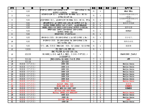
规 格 C65N C4 C65N D4 Z247-60 400V C2 C65N C2 C65N规格D2 C65N D2 C65N 400V50Hz C1 Z247-60 400V C1 GV2M308/2.5-4A规格 GV2ME07/1.6-2.5A GV2ME10/4-6.3A GV2ME16/9-214A SREAW RMC1-63 C6
PN:39874425,REV:08 EMI FILTER,DL-10D 250,10A, 50/60HZ,L:2*2.4mH,R:1.5M欧,C:2*0.47µF(X2),2*3300PF(Y) JBK3-250VA,50/60HZ,T40/E,IPOO JK3-550
C65N C63 C65N C40 C65N C32 C65N C25 C65N D25 C65N C16 C65N D16 C65N C10 multi9 C60a C10 5SJ62 MCB C10 400V 5SJ61 MCB C10 230V/400V DZ47C10 230/400V~6000A Multiq DPNK2 C10 50HZ230V C65N D10 C65N C6 Z247-60 400V C6 C65N D6
乐宇电气 铭纬自动化 施耐德
滤波器 变压器 变压器
断路器(空气开关) 断路器(空气开关) 断路器(空气开关) 断路器(空气开关) 断路器(空气开关) 断路器(空气开关) 断路器(空气开关) 断路器(空气开关) 断路器(空气开关) 断路器(空气开关) 断路器(空气开关) 断路器(空气开关) 断路器(空气开关) 断路器(空气开关) 断路器(空气开关) 断路器(空气开关) 断路器(空气开关)
单价
总价
生产厂家 Merlin Gerin Merlin Gerin CHNT Merlin Gerin Merlin Gerin Merlin Gerin Merlin Gerin CHNT 施奈德 Telemecanique Telemecanique Telemecanique 上海人民电器厂
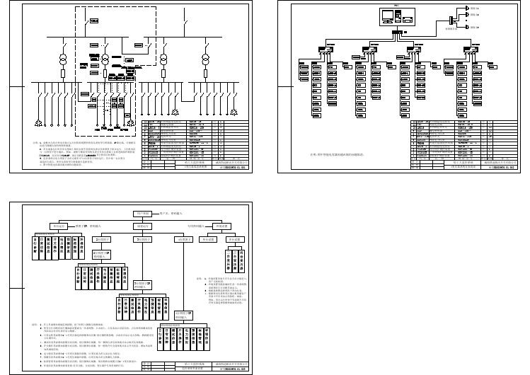
变压器监控系统图-变压器监控系统图
南京科远HCSE系列交流伺服用户手册(V1.02)
若在电源和伺服驱动器输入端之间加装接触器,则不允许用此接触器来控制伺服驱动器的启停。一定需要用该接触器控制 伺服驱动器的启停时,间隔不要小于一个小时。频繁的充放电易降低伺服驱动器内电容的寿命。若输出端和电机之间装有接触 器等开关器件,应确保伺服驱动器在无输出时进行通断操作,否则易造成伺服驱动器内模块损坏。 ■ 三相输入改成两相输入
HCSE系列交流伺服 用户手册
(V1.02)
南京科远电子科技有限公司
I
电机机型设置
用户拿到伺服驱动器和电机第一次运行时,请参照适配机型表(如果适配机型表中没有对 应的电机型号,请根据所用电机的额定转速和额定电流,来选择电机机型),确认电机机型设 置是否正确,如果不正确,运行时电机可能会出现振动或误报警现象,不能达到期望的控制效 果。机型参数为Pn223,属于隐藏参数,需要解锁方能进入,在数码管为“run”、”bb”或报 警状态显示界面下,按“上下下下”(一次UP键,三次DOWN键)即可解锁。机型设置正确后, 需重新上电,方可运行电机。以后如果电机型号有变动,则需重新设置。
1314面板按键操作说明1441按键的名称与功能1442基本模式的选择与操作1543状态显示16431位数据显示内容16432省略符号显示内容1644辅助功能模式下的操作fn17441辅助功能执行模式的用户参数一览及其功能17442显示伺服报警记录18443微动jog模式运行18444用户参数设定值进行初始化1945用户参数设定模式下的操作pn20451用户参数的设定2046监视模式下的操作un21461监视模式一览及其功能21462顺序用输入输出信号的监视显示22463指令脉冲计数器反馈脉冲计数器的监视显示2451试运行2452通用功能的设定25521伺服on设定25522超程设定25523伺服off时的停止方法选择2553位置控制运行25531用户参数的设定26532电子齿轮的设定27533编码器反馈信号输出分频系数27534位置指令28535平滑29537外部扭矩限制3054其他31541旋转检测速度31542超速报警功能31543数字输入接脚di输入滤波使能31544伺服控制信号输入input管脚功能配置
Banner Engineering Q40 Series 感应器说明书
Self-contained, dc-operated sensorsFor complete technical information about this product, including dimensions, accessories, and specifications, see/121516WARNING: Not To Be Used for Personnel ProtectionNever use this product as a sensing device for personnel protection. Do-ing so could lead to serious injury or death. This product does NOT include the self-checking redundant circuitry necessary to allow its use in personnel safety applications. A sensor failure or malfunction can cause either an ener-gized or de-energized sensor output condition.Models* Standard 2 m (6.5') cable models are listed.•9 m (30') cable: add suffix "W/30" (e.g., Q406E W/30).•4-pin Euro-style QD models: add suffix "Q " (e.g., Q406EQ ). A model with a QD connector requires a mating cable.DimensionsCabled ModelsQD Models40.1 mm (1.58")19.8 mm (0.78")Q40 Sensors - dc-Voltage Series Installation GuideP/N 116167 Rev. A5/30/201201161670HookupsNPN (Sinking) OutputsPNP (Sourcing) Outputs Cabled EmittersStandard HookupStandard Hookupbn bu10-30V dc+–10 - 30V dc+10 - 30V dc–Alarm HookupAlarm HookupNOTE: QD hookups are functionally identical.10 - 30V dc +–10 - 30V dc+–Fixed-Field Mode OverviewQ40 Series self-contained fixed-field sensors are small, powerful, infrared diffuse mode sensors with far-limit cutoff. The high excess gain of these sensors makes it possi-ble for them to detect objects of low reflectivity. The fixed-field design makes them ideal for detecting a part or surface that is directly in front of another surface, while ignoring the surface in the background.Excess GainThe excess gain curves for these products are available in the Photoelectric Sensors catalog or on the Ban-ner website. They show excess gain vs. sensing distance for sensors with 200 mm, 400 mm, and 600 mm (8", 16", and 24") cutoffs. Maximum excess gain for all models occurs at a lens-to-object distance of about 40 mm (1.57"). Sensing at or near this distance will make maximum use of each sensor’s available sensing power.Backgrounds and background objects must always be placed beyond the cutoff distance.These excess gain curves were generated using a white test card of 90% reflectance. Objects with reflectiv-ity of less than 90% reflect less light back to the sensor, and thus require proportionately more excess gain in order to be sensed with the same reliability as more reflective objects. When sensing an object of very low reflectivity, it may be especially important to sense it at or near the distance of maximum excess gain.The effects of object reflectivity on cutoff distance, though small, may be important for some applications.Sensing of objects of less than 90% reflectivity causes the cutoff distances to be “pulled” slightly closer to the sensor. For example, an excess gain of 1 for an object that reflects 1/10 as much light as the 90% white card is represented by the heavy horizontal graph line at excess gain = 10. An object of this reflectivity results in far limit cutoffs of approximately 190 mm, 250 mm, and 390 mm (7.48", 9.84", and 15.4") for the 200 mm, 400 mm, and 600 mm (8", 16", and 24") cutoff models, respectively.For highest sensitivity, the sensor-to-object distance should be such that the object will be sensed at or near the point of maximum excess gain. The background must be placed beyond the cutoff distance. Following these two guidelines makes it possible to detect objects of low reflectivity, even against close-in reflective backgrounds.or Cutoff Near Detector FarDetectorEmitter Object is sensed if amount of light at R1 is greater than the amount of light at R2Figure 1. Fixed-field ConceptAxisAs a general rule, the most reliable sensing of an object approaching from the side occurs when the line of ap-proach is parallel to the sensing axis.Figure 2. Fixed-field sensing axisSet-Up TipsIn the drawings and discussion in Excess Gain on page 2 and in Background Reflectivity and Placement on page 3, the letters E, R1, and R2 identify how the sensor’s three optical elements (Emitter “E,” Near Detector “R1,” and Far Detector “R2”) line up across the face of the sensor. In Figure 3. Reflective background - problem on page 3, Figure 4. Reflective background - solution on page 3, and Figure 5. Object beyond cutoff - problem on page 3, these elements align vertically; in Figure 6. Object beyond cutoff - solution on page 3, they align horizontally. Note how the pattern on the sensor’s lens helps to define the sensing axis of the sensor (Figure 2. Fixed-fieldQ40 Sensors - dc-Voltage Series Installation Guide - tel: 763-544-3164P/N 116167 Rev. Asensing axis on page 2). The sensing axis becomes important in situations like those illustrated in Figure 5. Object beyond cutoff - problem on page 3 and Figure 6.Object beyond cutoff - solution on page 3.Background Reflectivity and PlacementAvoid mirror-like backgrounds that produce specular reflections . False sensor response will occur if a background surface reflects the sensor’s light more strongly to the near detector (R1) than to the far detector (R2). The result is a false ON condition (Figure 3. Reflective background - problem on page 3). Use of a diffusely-reflective(matte) background will cure this problem. Other possible solutions are to angle the sensor or angle the background (in any plane) so the background does not reflect back to the sensor (see Figure 4. Reflective background - solution on page 3). Position the background as far beyond the cutoff distance as possible.An object beyond the cutoff distance, either moving or stationary (and when positioned as shown in Figure 5. Object beyond cutoff - problem on page 3), can cause unwanted triggering of the sensor because it reflects more light to the near detector than to the far detector. The problem is easily remedied by rotating the sensor 90°(Figure 6. Object beyond cutoff - solution on page 3) to align the sensing axis horizontally. The object then reflects the R1 and R2 fields equally, resulting in no false triggering. A better solution, if possible, may be to reposition the object or the sensor.Unwanted triggering of the sensor from an object beyond the cutoff can also be caused by attempting to sense a small object that is moving perpendicular to the sensor face, or by an object moving through the off-center position shown in Figure 5. Object beyond cutoff - problem on page 3. Making the object larger, centering the sensor relative to the object, or rotating the sensor to place the sensing axis perpendicular to the longer dimension of the object (Figure 6. Object beyond cutoff - solution on page 3) will solve the problem.Cutoff Reflective BackgroundFigure 3. Reflective background - problemE = EmitterR1 = Near Detector R2 = Far Detector CutoffFigure 4. Reflective background - solutionR1 = Near Detector R2 = Far Detector E = EmitterBackgroundorMoving ObjectCutoffFigure 5. Object beyond cutoff - problemCutoff Reflective BackgroundorMoving ObjectFigure 6. Object beyond cutoff - solutionSpecificationsSupply Voltage and Current10 to 30V dc (10% max. ripple)Supply current (exclusive of load current):Emitters: 25 mA Receivers: 20 mAPolarized Retroreflective: 30 mA Fixed-Field: 35 mASupply Protection CircuitryProtected against reverse polarity and transient voltagesRepeatabilityOpposed mode: 375 μsRetro and Fixed-Field: 750 μsRepeatability and response are independent of signal strength IndicatorsTwo LEDs (Green and Yellow)Green ON steady: power to sensor is ON Green flashing: output is overloadedYellow ON steady: N.O. output is conductingYellow flashing: excess gain marginal (1 to 1.5x) in light conditionQ40 Sensors - dc-Voltage Series Installation GuideP/N 116167 Rev. A - tel: 763-544-31643Output ConfigurationSPDT solid-state dc switch; Choose NPN (current sinking) or PNP (cur-rent sourcing) modelsLight Operate: N.O. output conducts when sensor sees its own (or the emitter's) modulated lightDark Operate: N.C. output conducts when the sensor sees dark; theN.C. (normally closed) output may be wired as a normally open marginal signal alarm output, depending upon hookup to power supply (U.S. pat-ent 5087838)Output Rating150 mA maximum (each) in standard hookup.When wired for alarm output, the total load may not exceed 150 mA.OFF-state leakage current: < 1 microamp @ 30V dcON-state saturation voltage: < 1V at 10 mA dc; < 1.5V at 150 mA dc Output Protection CircuitryProtected against false pulse on power-up and continuous overload or short circuit of outputsOutput Response TimeOpposed mode: 3 ms ON, 1.5 ms OFFRetro and Fixed-Field: 3 ms ON and OFFNOTE: 100 ms delay on power-up; outputs do not conduct during thistime.ConstructionPBT polyester housing; acrylic lensEnvironmental RatingLeakproof design rated NEMA 6P, IEC IP67. QD Models rated IP69K per DIN 40050-9.Connections2 m (6.5') or 9 m (30') attached cable, or 4-pin Euro-style quick-discon-nect fittingOperating ConditionsTemperature: -40° to +70°C (-40° to 158°F)Maximum relative humidity: 90% at 50°C (non-condensing) Vibration and Mechanical ShockAll models meet Mil. Std. 202F requirements. Method 201A (Vibration;frequency 10 to 60 Hz, max., double amplitude 0.06" acceleration 10G).Method 213B conditions H&I (Shock: 75G with unit operating; 100G for non-operation)Quick-Disconnect (QD) CablesBanner Engineering Corp Limited WarrantyBanner Engineering Corp. warrants its products to be free from defects in material and workmanship for one year following the date of shipment. Banner Engineering Corp. will repair or replace, free of charge, any product of its manufacture which, at the time it is returned to the factory, is found to have been defective during the warranty period. This warranty does not cover damage or liability for misuse, abuse, or the improper application or installation of the Banner product.THIS LIMITED WARRANTY IS EXCLUSIVE AND IN LIEU OF ALL OTHER WARRANTIES WHETHER EXPRESS OR IMPLIED (INCLUDING, WITHOUT LIMITATION, ANY WARRANTY OF MERCHANTABILITY OR FITNESS FOR A PARTICULAR PURPOSE), AND WHETHER ARISING UNDER COURSE OF PERFORMANCE, COURSE OF DEALING OR TRADE USAGE.This Warranty is exclusive and limited to repair or, at the discretion of Banner Engineering Corp., replacement. IN NO EVENT SHALL BANNER ENGINEERING CORP. BE LIABLE TO BUYER OR ANY OTHER PERSON OR ENTITY FOR ANY EXTRA COSTS, EXPENSES, LOSSES, LOSS OF PROFITS, OR ANY INCIDENTAL, CONSE-QUENTIAL OR SPECIAL DAMAGES RESULTING FROM ANY PRODUCT DEFECT OR FROM THE USE OR INABILITY TO USE THE PRODUCT, WHETHER ARIS-ING IN CONTRACT OR WARRANTY, STATUTE, TORT, STRICT LIABILITY, NEGLIGENCE, OR OTHERWISE.Banner Engineering Corp. reserves the right to change, modify or improve the design of the product without assuming any obligations or liabilities relating to any product previously manufactured by Banner Engineering Corp.Q40 Sensors - dc-Voltage Series Installation Guide。
P+F倍加福安全栅选型指导
1个有源4-20mA信号输入DCS/PLC。
2组单刀双掷继电器报警信号输入DCS/ESD/PLC。
用面板按键组态或PC机组态。两组继电器可进行高报或低报的任意组合。带显示。
KFD2-CRG-1.D
不含安全栅功能。其他同KFD2-CRG-EX1.D。
KFU8-CRG-EX1.D
供电:AC48-253V;DC20-90V。
KFD2-ST2-EX1.LB
单通道。
0-24V /5kHz频率信号输入DCS/PLC。现场线路监测。
KFD2-UFC-EX1.D
单通道。0.001Hz~5kHz频率。送1个0-24V无源频率信号、1个可设定量程的有源4-20mA信号、2个继电器报警信号输入DCS/PLC。现场线路监测。
PI,0-12V有源电压频率
热电偶应用时请订购冷端补偿器K-CJC。
PC机组态。可选PW-PK-KE组态软件包。
KFD2-UT2-EX2
双通道。
DI,NAMUR型开关信号或干接点信号。
(本栏隔离栅均有现场线路监测,并经电源模块实现故障报警。)
KFD2-SR2-EX2.W
双通道。继电器干接点信号输入DCS/PLC。
KFD2-SR2-EX1.W
KFD2-VR-EX1.18
单通道。
4kHz / 0-12V有源电压频率输入DCS/PLC。
PI,Bentley Nevada频率量传感器
KFD2-VR4-EX1.26
单通道。
Pick-up振动频率信号输入Bentley Nevada系统。
AI,4-20mA。2或3线制变送器。有源4-20mA信号
KFD2-CRG-EX1.D
单通道。继电器干接点信号输入DCS/PLC。
PESSRAE PESSRAL型式试验与现场检验(上海交大 胡晖)
产品概念
产品设计
验证与确认
功 能 安 全 管 理
型式试验内容——产品概念
安全要求规范(SRS) 安全确认计划 (V-V)
产品概念——安全要求规范
安全功能和 安全完整性等级 工作模式 故障响应时间 工作环境 电磁抗干扰
产品概念——安全功能
自动扶梯和自动人行道电气安全装置(或功能)
PESSRAE所检查的装置 检查超速并在速度超过名义速度1.2倍之前起作 用;向上运行时,检查非操纵逆转 最低安全完整性 等级(SIL) 2
产品设计—— FMEDA
元器件的失效率计算
元器 件 元器 件号 失效模式 失效模式 开路 C* 104 短路 数值随机变化 Tanα变化 开路 R* 1K 短路 数值随机变化 百分比 40 40 10 10 80 10 10 λTotal 诊断 状态 λS λSD 0 0 0 0 0 0 0 λsu 0.24 0 0.06 0.06 0.14 0 0.02 λDD 0 0.24 0 0 0 0.02 0 λD λDU 0 0 0 0 0 0 SN29500 0 SN29500 失效数 据来源
产品概念——软件安全要求规范 可编程电子硬件故障诊断 指令、传感器、执行器故障诊断 电源故障诊断 软件故障诊断
传感器 子系统
逻辑 子系统
输出 子系统
型式试验内容——产品设计
硬件设计 软件设计
产品设计——硬件设计
硬件系统结构设计详细描述; 电路板的布线图和布置说明; 故障(失效)模式、影响或诊断分析(FMEA或 FMEDA); 随机硬件失效引起的安全功能失效的概率(PFH) 和子系统安全失效分数(SFF)分析和估算说明;
产品设计——硬件结构设计要求 产品设计中硬件结构的选取 ISO22201对系统结构的规定(与IEC61508不同)
非洲猪瘟快检设备
非洲猪瘟快检设备تادعمةيقيرفلأافشكلاريزانخلا非洲猪瘟快检设备JD-PCR ىمحعيرسلا竞道非洲猪瘟检测仪配套非洲猪瘟病毒荧光pcr检测试剂盒、非洲猪瘟病毒荧光pcr核酸检测试剂盒均已经获得农业农村部产品批准,可以满意非洲猪瘟核酸现场快速检测需求。
可定量快速畜牧类疾病诊断如非洲猪瘟、禽感、猪瘟、猪蓝耳、伪狂犬等疾病,广泛应用于养殖场、屠宰场、食品加工厂、肉产品深加工企业、农业农村部、畜牧局、检验检疫单位使用。
仪器特点1.体积小,重量轻,易于携带。
轻松满意外出试验的需求。
2.内置7寸高清电容屏PDA,触屏操作,简便快捷。
3.Marlow高品质Peltier制冷片,结合德国PT1000温度传感器以及电性电阻加热补偿边缘的温度掌握模式,大升温速度7℃,大降温速度5℃,大大缩短试验时间。
4.整板3s快速采光模式,保证明验结果孔位全都性。
5.简洁直观的软件引导,轻松开启检测试验。
非洲猪瘟PCR检测仪应用领域□ 基础科学讨论□ 病原体检测□ 肉制品掺假□ 转基因检测□ 食品平安检测□ 药物开发及合理用药□ 基因表达□ 水体监测四、技术参数样品容量:8x0.2ml、支持8联管适用耗材:常见透亮PCR 耗材,8x0.2ml 排管,0.2ml 单管反应体系:5-120ul反应模式体系加热/制冷模块:进口半导体热电模块温度掌握范围:4C-99℃升降温平均速率2C/秒温控精度:0.1C温度匀称性: 0.2C温控区域数量:多点(2 点)梯度数:0 个梯度温度范围:无梯度孔数:无激发光源:免维护led激发光波长范围:400-700nm检测部件:进口光电检测器检测通道数:标配 1通道(FAM)、高配(选配)(FAM、VIC)适用染料和探针:FAM/SYBR Green I, VIC/HEX/CY3(选配), ROX/Texas Red(选配), Cy5,TAMARA(选配)软件功能:荧光定量 PCR 系统软件; 实时扩增反应曲线功能;特定标本实时反应曲线显示;数据分析功能;阴阳结果自动判定功能;图形化显示功能。