
Mini红外避障传感器用户手册v2.0
三、 规格参数
1.产品名称:Mini红外避障传感器
2.产品货号:RB-02S003
-3-
奥松机器人
3.工作电压:DC 3.3V~5V 4.工作电流:≥20mA 5.工作温度:-10℃ ~ +50℃ 6.检测距离:3~35cm 7.IO接口:4线制接口(-/+/S/EN) 8.输出信号:TTL电平(有障碍物低电平,无障碍物高电平) 9.调节方式:多圈电阻式调节 10. 有效角度:35° 11. 模块尺寸:28mm×23mm 12. 模块重量:9g
RobotBase 与
为哈尔滨奥松机器人科技有限公司注册商标。
基于对产品的持续完善与升级,本公司随时更改本资料或其中所提及的产品概不
另行通知。未经本公司书面同意或授权,不可擅自盗用、复制、出版本产品说明中局
部或全部内容。
免责声明:
使用者在使用本产品所做的任何应用(如实验、竞赛、二次开发),使用者须自行 承担风险。公司对于因使用本产品所产生的直接、间接或附带伤害(包括人身安全损 失、利润信誉损失等),不负任何责任,未满 14 岁儿童须在成人陪同下方可使用本产 品进行相关实验。
pinMode(pinI1,OUTPUT); pinMode(pinI2,OUTPUT);
pinMode(speedpin,OUTPUT); pinMode(pinI3,OUTPUT); pinMode(pinI4,OUTPUT); pinMode(speedpin1,OUTPUT); pinMode(IRR,INPUT); pinMode(IRM,INPUT); pinMode(IRL,INPUT); } void advance(int a)//前进
2. 请认真查看引脚功能说明,注意简明标识符,正确接线!切勿将电源线接反,造成
电子器件烧毁。
3. 接反电源会导致传感器电路板的损坏。传感器在出厂前经过了全面的测试,正常情
况下不要调节频率调节电位器。
4. Mini 红外探测传感器探测浅颜色物体的距离比深色物体的要远,所以调节传感器时
要将物体颜色和探测距离综合考虑。此外,Mini 红外探测传感器可以用在除机器人以
-7-
奥松机器人
{ analogWrite(speedpin,a);//输入模拟值进行设定速度 analogWrite(speedpin1,a); digitalWrite(pinI4,LOW);//使直流电机(右)逆时针转 digitalWrite(pinI3,HIGH); digitalWrite(pinI1,LOW);//使直流电机(左)顺时针转 digitalWrite(pinI2,HIGH);
back(120); delay(300); right(100); delay(100); } if(l==LOW &&m==HIGH && r==LOW ) { back(120); delay(300); right(100); delay(100); } if(l==HIGH &&m==LOW && r == HIGH )
公司网址: 机器人视频播客网址:/robotbase 奥松机器人基地微博:/robotbase
-2-
奥松机器人
一、注意事项
RobotBase
1. 在未认真阅读本说明之前请勿给加电!以免错误接线造成传感器永久损坏。
-8-
RobotBase
奥松机器人
void loop() {
int r,m,l; r=digitalRead(IRR); m=digitalRead(IRM); l=digitalRead(IRL); if(l==HIGH &&m==HIGH && r==HIGH) advance(120); if(l==LOW &&m==LOW && r==LOW ) {
} void right(int b)//右转 {
analogWrite(speedpin,b);//输入模拟值进行设定速度 analogWrite(speedpin1,b); digitalWrite(pinI4,HIGH);//使直流电机(右)顺时针转 digitalWrite(pinI3,LOW); digitalWrite(pinI1,LOW);//使直流电机(左)顺时针转 digitalWrite(pinI2,HIGH); } void left(int c)//左转 { analogWrite(speedpin,c);//输入模拟值进行设定速度 analogWrite(speedpin1,c); digitalWrite(pinI4,LOW);//使直流电机(右)逆时针转 digitalWrite(pinI3,HIGH); digitalWrite(pinI1,HIGH);//使直流电机(左)逆时针转 digitalWrite(pinI2,LOW); } void stop()//停止 { digitalWrite(pinI4,HIGH);//使直流电机(右)制动 digitalWrite(pinI3,HIGH); digitalWrite(pinI1,HIGH);//使直流电机(左)制动 digitalWrite(pinI2,HIGH); } void back(int d)//后退 { analogWrite(speedpin,d);//输入模拟值进行设定速度 analogWrite(speedpin1,d); digitalWrite(pinI4,HIGH);//使直流电机(右)顺时针转 digitalWrite(pinI3,LOW); digitalWrite(pinI1,HIGH);//使直流电机(左)逆时针转 digitalWrite(pinI2,LOW); }
RobotBase
四、Mini 红外避障传感器模块的功能图解
-4-
奥松机器人
RobotBase
1、传感器的接口:共 4 个,电路板标号分别为 EN、S、+、-。分别是传感器使能
端口、检测信号输出端口、Vcc、GND。
EN(传感器使能):置高,传感器不工作;置低,传感器工作。
S(反射信号输出):当 EN 置低的情况下,如果没有检测到物体,则 S 端口保持
勘误说明:
为了能够正确的传达产品的使用信息,我们花费很多时间和精力在这本手册上, 希望使用者能够认真阅读其中内容,然而难免仍有疏漏之处。如在本手册中发现错误, 欢迎利用电子邮件 robotbase@ 与我们联络。为了使手册更加完善,提供最 新最详实的资讯,我们会持续改善增补手册中内容。如有任何相关资讯更新皆会发布 在相4725590100i20b.html)这是实验代码的博文地址。
Arduino 实验代码如下。
int pinI1=8;//定义 I1 接口 int pinI2=9;//定义 I2 接口 int speedpin=11;//定义 EA(PWM 调速)接口 int pinI3=6;//定义 I3 接口 int pinI4=7;//定义 I4 接口 int speedpin1=10;//定义 EB(PWM 调速)接口 int IRR=3;//定义右侧避障传感器接口 int IRM=4;//定义中间避障传感器接口 int IRL=5;//定义左侧避障传感器接口 void setup() {
奥松机器人
RobotBase
Mini 红外避障传感器模块 用户手册 v2.0
公司网址: 公司电话:18945688768 机器人技术博客:/robotbase Arduino 教学博客:/arduino
4、 2WD 小车×1
5、 传感器支架×1
6、 通用 3P 传感器连接线×3
7、 杜邦线若干
8、 USB 数据通信线×1
通过配合调节调频和调距两个电位计,调到适合我们的检测距离。有障碍物位低
电平,无障碍物位高电平。使能跳线帽插上就是一直让传感器工作,拔下则可以通过
控制使能端让传感器是否工作。下面的实验代码是我们引用 Arduino 爱好者的一篇博
外的其它地方。传感器可以用在一个小区域内检测物体的存在,用于红外开关等。用
户可以发挥自己的想象,用在其它合适的场合。
二、产品介绍
Mini IR Dectector 是机器人基地专为轮式机器人设计的一款距离可调式避障传感 器。此传感器对环境光线适应能力强、精度高,其具有一对红外线发射与接收管,发 射管发射出一定频率的红外线,当检测方向遇到障碍物(反射面)时,红外线反射回 来被接收管接收,此时指示灯亮起,经过电路处理后,信号输出接口输出数字信号, 可通过电位器旋钮调节检测距离,有效距离 3~35cm,工作电压为 3.3V-5V,由于工作 电压范围宽泛,在电源电压波动比较大的情况下仍能稳定工作,适合多种单片机、 Arduino 控制器、BS2 控制器使用,安装到机器人上即可感测周围环境的变化。
{ back(120); delay(300); right(100); delay(100); } if(l==LOW && m==LOW && r ==HIGH ) right(100); if(l==LOW && m==HIGH && r ==HIGH) right(80); if(l==HIGH && m==LOW && r == LOW ) left(100); if(l==HIGH && m==HIGH && r==LOW ) left(80); }
上。
3、调节距离电位器:用于调整传感器探测的距离。当用户需要调整探测距离时,
用螺丝刀调整电位器阻值,按箭头方向旋转是将探测距离减小,相反方向旋转探测距
离增大。
4、频率调节电位器:用于产生 38KHz 频率的方波。正常情况下,在出厂前将阻
Mini红外避障传感器用户手册v2.0

-8-
RobotBase
奥松机器人
void loop() {
int r,m,l; r=digitalRead(IRR); m=digitalRead(IRM); l=digitalRead(IRL); if(l==HIGH &&m==HIGH && r==HIGH) advance(120); if(l==LOW &&m==LOW && r==LOW ) {
上。
3、调节距离电位器:用于调整传感器探测的距离。当用户需要调整探测距离时,
用螺丝刀调整电位器阻值,按箭头方向旋转是将探测距离减小,相反方向旋转探测距
离增大。
4、频率调节电位器:用于产生 38KHz 频率的方波。正常情况下,在出厂前将阻
值调好,无需用户调节。但由于外界环境的不同或振动,出现了接收不到反射信号的
文,(/s/blog_5e4725590100i20b.html)这是实验代码的博文地址。
Arduino 实验代码如下。
int pinI1=8;//定义 I1 接口 int pinI2=9;//定义 I2 接口 int speedpin=11;//定义 EA(PWM 调速)接口 int pinI3=6;//定义 I3 接口 int pinI4=7;//定义 I4 接口 int speedpin1=10;//定义 EB(PWM 调速)接口 int IRR=3;//定义右侧避障传感器接口 int IRM=4;//定义中间避障传感器接口 int IRL=5;//定义左侧避障传感器接口 void setup() {
MODbuS 微型红外温度传感系统说明书

JModels with Display Only U 4 to 20 mA or RS485 MODbuS ®Outputs U M iniature SensingHead and Configurable Electronics Module U S creen Color Change Indicates Alarm Mode U D ata Logging to MicroSD Card on Touch Screen Models U A larm Relay, Outputs Rated 24 Vdc—No Need for Separate Trip Amplifier U M aximum, Minimum, Average andInstantaneous Readings, Peak or Valley Hold, Reflected Energy CompensationStandard Features for Models with or without Display U H igh-Ambient Sensing Head Withstands up to 180°C (356°F) Without Cooling U A djustable Emissivity Setting— Suitable for a Wide Range of Target Materials Such as Paper, Plastics, Food, Painted Surfaces and Many More U T emperature Ranges from -20 to 1000°C (-4 to 1832°F)U R esistant to Interference from Movement of Sensing Head Cable—Ideal for Mounting on Robot ArmsMiniature InfraredTemperature Sensor SystemWith Optional High-Ambient Sensing Head and Touch Screen Displayto IP65OS-MINI SeriesThe new Omega ® mini infrared pyrometer is packed full ofexciting new features. Its miniature sensing head measures just 18 x 45 mm (0.71 x 1.8"), making it ideal for mounting in tight spaces. a high ambient version is capable of withstanding temperatures of up to 180°C (356°F) without water or air-cooling, allowing significant energy and cost savings to be made. manufactured from 316 stainless steel and sealed to IP65, the Omega mini sensing head is ideal for food and pharmaceutical applications among many others.a wide selection of optics allows the Omega mini to focus on small or large targets at short or long distances.The special low-noiseinterconnecting cable is resistant to interference from movement, making the sensing head ideal for mounting on robot arms. It can be supplied in lengths from 1 to 30 m (3.3 x 98').The electronics module is also available with a number ofdifferent options: The backlit touch screen interface provides a large, bright display of the measured temperature in digital format and a graph view that shows the history of the measured temperature. It also enables full configuration ofOS-MINI302-D-MA shown smaller than actual size.Comes with miniature sensing head.Optional touch screen for temperature indication and configuration.the sensor including temperature range setting between-20 to 1000°C (-4 to 1832°F), adjustable filtering, peak or valley hold processing, emissivity setting and reflected energy compensation. In alarm conditions, the whole display changes color to provide an immediate and obvious alarm indication. alarm modes and levels can be configured via the touch screen. When fitted with a microsd card, the Omega minialso functions as a data logger,providing a useful means ofrecording process temperaturesfor quality assurance andtraceability. The user can selectthe sample rate and the numberof samples to be taken andschedule the data logging tostart at a certain time. With a2 gb card, the user can store28.4 million time and datestamped readings, which providesalmost 1 year’s worth of data atthe fastest possible sample rateof 1 per second.Output options include 4 to20 ma, Rs485 mOdbus andalarm relays, which are rated24 Vdc so there is no need fora separate trip amplifier. Otheroptions include mounting brackets,an air purge collar, protective lenscover and laser sighting tool.24 Vdc100 mA -CB and -CRT models 24 Vdc 100 mA-BB and -BT modelsConnectionsSpecificationsMaximum Temperature Span(Touch Screen Models): 1020°C (1868°F)Minimum Temperature Span (Touch Screen Models): 100°C (212°F)Output: 4 to 20 ma or Rs485 mOdbusAccuracy:is greaterRepeatability: ± 0.5°C or 0.5%, whichever is greaterEmissivity Setting Range: 0.20 to 1.00Emissivity Setting Method:MA Models: in electronics boxMODbuS Display Models: Via Rs485; via touch screenResponse Time, t90: 240 ms (90% response)Spectral Range: 8 to 14 μmSupply Voltage: 24 Vdc ± 5%Maximum Current Draw: 100 ma Maximum Loop Impedance(MA and MA-R-D Models): 900 Ω (4 to 20 ma output)Models):alarm relays rated 24 Vdc, 1 a,isolated 500 VdcCable Length (Sensing Head to Electronics Module): 1 m (3.3') (standard), up to 30 m (98.4')(optional)Ambient Temperature (Sensing MA and MA-R-D C4 and C4-R-DModels with Touch Screen DisplayModels with RS485/MODbuS OutputJModels with No DisplaySD card adaptor.* To order, specify model number, temperature range, output and interface, for an additional cost.** Insert cable length in meters. Extended cable is added to standard cable length, add suffix to model number, for an additional cost.Ordering Examples: OS-MINI152-D-MA, miniature infrared temperature sensor with 15:1 optics, touch screen and configurable temperature range from -20 to 1000°C (-4 to 1832°F).OS-MINI302-MA-XT, miniature infrared temperature sensor with 30:1 optics, 4 to 20 mA output and fix range from 0 to 1000°C (32 to 1832°F).OS-MINI-HA201-D-C4, miniature infrared temperature sensor with high ambient sensing head and 20:1 optics, RS485 MODBuS, relay and touch screen. OCW-3, OMEGACARE extends standard 2-year warranty to a total of 5-year warranty.OS-MINI152-MA-MT-MINI-PMCE-(3), miniature infrared temperature sensor with 15:1 optics, 4 to 20 mA output, 0 to 250°C (32 to 482°F) rangeand 3 m (10') of extension cable.Options and Accessories K Type High Ambient Sensing HeadAir purge collar.Laser sighting tool.Measurement Temperature Range Specify temperature range from table below.。
MINI SMD 数字 AD 型热释电红外传感器 使用说明书

MINI SMD 数字AD 型热释电红外传感器Mini SMD AD Pyroelectric Infrared SensorsS22-P330Y 使用说明书V1.3森霸传感科技股份有限公司Senba Sensing Technology Co.,Ltd.森霸传感科技股份有限公司1.企业及产品概况:1.1体系认证●ISO14001认证公司获得ISO14001认证,在遵守国家环保法的基础上,通过采取各种改进措施,实现企业可持续性发展。
●ISO 9001认证公司获得国际标准化机构(ISO)的品质保证标准-即“ISO 9001”的认证。
1.2关于欧盟ROHS指令ROHS指令:欧盟提出的“关于在电子电气设备中限制使用某些有害物质的指令2011/65/EC”,公司生产的所有产品均符合欧盟ROHS指令。
1.3产品型号及检测原理1.3.1产品规格型号:本产品为SMD 数字AD 型双元热释电红外传感器,产品型号为S22-P330Y ,版本号为V1.3,若使用产品超出了产品列举的应用范围,请及时咨询产品应用或销售工程师。
1.3.2产品探测原理:传感器核心部件由热释电探测敏感元、红外滤光片和芯片IC三部分组成,其中探测敏感元为双元结构。
产品是将AD芯片与人体探测敏感元都集成在电磁屏蔽罩内的热释电红外传感器。
人体探测敏感元将感应到的人体移动信号传输到AD芯片上,其通过采集、滤波等输出16位数字信号,并通过外围电路的单片机实现相关功能。
2.非商业用途说明森霸传感科技股份有限公司(以下简称森霸)免费授权用户非商业性使用本产品说明书,并为用户提供产品变更和咨询服务。
若要进行商业性的销售、复制、散发或其他商业活动,须事先获取森霸的书面授权和许可。
另外,用户在使用本产品说明书时,不得违反法律、危害公共安全或损害第三方合法权益,森霸不承担由此引发的任何索赔责任。
3.产品说明3.1产品命名规则示例S:贴片型22:产品分类P:窗口:窗口尺寸4*43:感应单元:敏感元为双元结构3:脚位:功能脚位数量为30:红外滤光片:探测波长5-14um Y:芯片:表示其型号代码为YS22—P33Y森霸传感科技股份有限公司3.2产品特点⏹小型化⏹SMD回流焊贴装工艺⏹16位数字信号输出⏹单线串行数据⏹低电压、微功耗⏹适合超薄的产品外观设计3.3产品应用领域消费电子应用:⏹玩具⏹数码相框、门铃⏹电视机、冰箱、空调智能家居、安防应用:⏹USB报警器⏹入侵检测⏹网络摄像机⏹局域网监控器⏹私人警报器⏹汽车防盗系统灯饰应用:⏹室内、庭院、走廊、楼梯灯等的自动亮起和熄灯等3.4产品及推荐的焊盘尺寸图推荐焊盘尺寸图注:1、传感器双元结构,以X 向做左右横切运动时,其感应视角最大且探测距离最远。
Mini Beamer 传输器与接收器快速使用指南说明书
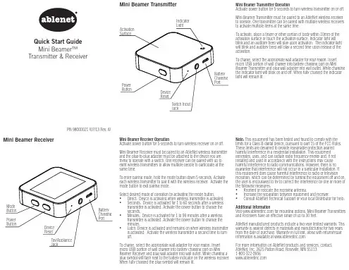
Note: This equipment has been tested and found to comply with the limits for a Class B digital device, pursuant to part 15 of the FCC Rules. These limits are designed to provide reasonable protection against harmful interference in a residential installation. This equipment generates, uses, and can radiate radio frequency energy and, if not installed and used in accordance with the instructions may cause harmful interference to radio communications. However, there is no guarantee that interference will not occur in a particular installation. If this equipment does cause harmful interference to radio or television reception, which can be determined by turning the equipment off and on, the user is encouraged to try to correct the interference by one or more of the following measures: • Reorient or relocate the receiving antenna. • Increase the separation between equipment and receiver. • Consult AbleNet Technical Support or your local Distributor for help.
MINI-BEAM 系列 传感器 说明书

P •Email: sensors@197 MINI-BEAM专家型TM传感器MINI-BEAM®专家型TM注意:i) 电缆式传感器型号后缀加“W/30”,电缆长度为9m(如:SME312FPB W/30)ii)型号后带QD的产品需另配接插件。
•Email: sensors@199 MINI-BEAM专家型TM传感器MINI-BEAM®专家型TM200MINI-BEAM 专家型TM 传感器M I N I -B E A M ®E x p e r t T M˝…¤31.2 mm(1.23")MINI-BEAM 专家型系列传感器(后缀LP ,LPC ,D ,DV ,CV ,CV2,CVG ,CVB ,及)电缆式接插件式MINI-BEAM 专家型系列传感器宽光束直接反射式(后缀为W 型)MINI-BEAM 专家型系列传感器玻璃光纤式(后缀为F ,FV ,FVG ,FVB 和FVW 型)MINI-BEAM 专家型系列传感器塑料光纤式(后缀为FP ,FPG ,FPB 和FPW 型)MINI-BEAM 专家型系列传感器-后视图 •Email: sensors@209 MINI-BEAM系列传感器MINI-BEAM®系列对于标准的MINI-BEAM:i) 电缆式传感器型号后加后缀“W/30”,电缆长度为9m(如:SM312FP W/30)ii) MINI-BEAM电缆式接插件型号后缀为“QDP”,长度150mm(如SM312FPQDP)iii) 型号后带QD的产品需另配接插件210MINI-BEAM 系列传感器M I N I -B E A M ®S e r i e s注意:直流MINI-BEAMs 如加上后缀“MHS ”(如:SM312LVMHS )则为高速型,响应时间0.3ms ,但同时减小了检测距离和过量增益。
•Email: sensors@211MINI-BEAM 系列传感器MINI-BEAM ®系列直流系列电缆式直流系列接插件式(4针Euro型)直流电缆式发射器直流接插件式发射器(4针Euro 型)4针Euro 型出线图可选接插件(QD )式直流MINI-BEAM 型传感器具有2m(6.5')或9m(30')的PVC 电缆,或是一个4针Euro 型的QD 接插件。
小区域红外发射器用户手册说明书

IR T1Small Area Infrared TransmitterMAN 212HIR T1 Small Area Infrared TransmitterImportant Safety InstructionsPlease read and keep these instructions.WARNING! To reduce the risk of fire or electric shock, do not expose the system to rain or moisture. Do not use this apparatus near water. The system should not be exposed to dripping or splashing, and objects filled with liquids such as beverages should not be placed on the transmitter or receivers. Clean only with a dry cloth.Attempting to service this device will void the warranty • Refer servicing to qualified personnel. Servicing is required when the system has been damaged in any way: if liquid has been spilled or objects have fallen into the unit, if the unit has been exposed to moisture, if the unit does notoperate normally, or if the unit has been dropped.• Do not block any ventilation openings. Install in accordance withmanufacturer’s instructions.• Do not install near any heat sources such as radiators, heat registers,stoves, or other apparatus that produces heat.• Use only attachments/accessories specified by the manufacturer.• Unplug the transmitter during lightning storms or when unused for long periods of time.• Be advised that different operating voltages require the use of differentattachment plugs. Check the voltage in your area and use the correct type.• Use only the power supply provided by Williams AV. Other power supplies may have similar specifications, but may not be equivalent in emissionsratings, in-rush current, etc. Use of an unapproved power supply may leave the device partially or completely inoperable, and will void the warranty.• Protect the power cord from being walked on or pinched, particularly atplugs, receptacles, and near the power jack on the transmitter.• This apparatus must be grounded.• The AC Power plug or an appliance coupler is used as the disconnectdevice, so the disconnect device should remain readily operable.For Customers in The United StatesThis equipment has been tested and found to comply with the limits for Class B digital device, pursuant to part 15 of the FCC rules.For Customers in CanadaThis Class B digital device meets all requirements of the Canadian Interference-causing Equipment Regulations. Cet appareil numérique de la classe B respecte toutes les exigencies du Règlement sur le matériel brouilleur du Canada.IR T1 Small Area Loop Infrared Transmitter Recycling InstructionsPlease help Williams AV protect the environment. Please take the time to dispose of your equipment properly.Product Recycling for Customers in the European Union:Please do NOT dispose of your Williams AV equipment in the householdtrash. Take the equipment to a electronics recycling center, or return theproduct to the factory for proper disposal.System OverviewThe IR T1 is a two-channel infrared transmitter combining infrared modulator and emitter technology into a single mountable enclosure—which reduces operating costs, eliminates the need for rack space and eases set-up.The IR T1 is ideal for high quality audio programs such as music, television audio, and audio description. The IR T1 will accept any line level stereo audio input. Infrared receivers detect the transmission and convert the light signals backinto audio signals. The IR T1 operating frequencies (2.3/2.8 MHz) minimize high efficiency lighting interference.No FCC license or radio approval is required with this equipment. It can be used anywhere in the world.NOTE: This equipment has been tested and found to comply with the limits fora Class B digital device, pursuant to part 15 of the FCC Rules. These limits are designed to provide reasonable protection against harmful interference when the equipment is operated in a commercial environment. This equipment generates, uses, and can radiate radio frequency energy and, if not installed and used in accordance with the instruction manual, may cause harmful interference to radio communications. Operation of this equipment in a residential area may cause interference, in which case the user will be required to correct the interference at his own expense.NOTE: A PLASMA MONITOR OR TELEVISION CAN DEGRADE THE AUDIO QUALITY OF THE IR T1 TRANSMITTER. FOR BEST PERFORMANCE, THE TRANSMITTER SHOULD BE POSITIONED AS FAR AWAY AS POSSIBLE FROM ANY PLASMA MONITOR, TELEVISION OR OTHER INTERFERING DEVICES. Installation ProceduresDetermine Coverage AreaWhen using the IR T1 transmitter with the RX22-4 receiver, the system coverage area will exceed 1,300 sq. ft. (120 sq. m.). Other receivers may have a reduced coverage area. Figure 1 illustrates typical coverage pattern for the IR T1. This can be affected by direct/indirect sunlight, reflections on walls, objects in the room and room construction. The patterns illustrated are the direct radiation pattern. Most objects block infrared light, so the transmitter cannot be concealed behind walls, glass, curtains, etc. The infrared radiation does not drop to zero outsidethe illustrated patterns; it decreases. It still may be useable at a greater distance, depending on the receiver sensitivity and the reflective characteristics of the room. Important: Remember to point the transmitter towards the listening audience. The front is the surface with the Williams AV logo as shown on the cover of this manual.See Figure 1 on the next page for a coverage pattern.IR T1 Small Area Infrared Transmitter Figure 1 - IR T1 Coverage PatternWIR RX22-4 Receiver - solid line || IR RX20 - dashed lineConnections & IndicatorsFigure 2 - IR T1 Rear ViewConnecting Power1. Snap in the correct adapter for your region into the TFP 055 power supply.2. Plug the USB end of the “USB to micro USB cord” into the power supply.3. Plug the micro USB end of the “USB to micro USB cable” into the IR T1.4. Plug the power supply into an AC outlet.Alternatively, you may plug the USB end of the cord into a direct USB power source, such as the USB port on a television, etc. to power the IR T1.On power up, the IR T1 performs a self-test to detect damage due to shipping, handling, tampering or incorrect operation. If any failure is present, the green power LED will blink rapidly. If this occurs, contact Williams AV Customer Service. This system is designed for class 2, low-voltage wiring. Always follow local electrical codes when using low-voltage wiring.IR T1 Small Area Loop Infrared Transmitter Audio Indicators (Ch. 1,2)The audio indicator LEDs (see Figure 2) will light up yellow when an adequate level of input audio is sensed on that channel. If audio is present, but not high enough to produce acceptable audio quality, the LED will not light. Once an adequate level of audio is fed to the unit, the LED will stay on. If the audio level falls below the acceptable threshold, the LED will go out, and the sleep timer will start to turn off that channel after approximately 12 minutes (See “Sleep Mode” below).Sleep ModeThe IR T1 is equipped with a sleep mode/power save feature. If a minimum acceptable audio level is not present on a channel (both channels are independent), a timer begins, and after approximately 12 minutes that channel will automatically go into sleep/power save mode. The timer begins when the yellow channel LED goes out. Both channels are independent; one can be broadcasting while the other goes to sleep (shuts off infrared output).This mode decreases power consumption by 80 percent. Audio will automatically begin broadcasting again when the audio input threshold is triggered.Connecting the Audio SourceThe IR T1 detects the presence of audio on the Audio Line Input jack, lights up the LED for the channel(s) where an adequate level of incomiing audio is present, and transmits on either/both channels.The IR T1 will accept line level mono or stereo audio inputs. See figure 3 for audio input cable configuration.The IR T1 uses a limiter circuit to control the gain of line level audio for optimum transmission. The yellow Audio Indicator LED should stay on when when an adequate level of input audio is present. If the audio indicators do not stay on, the audio level is too low. Adjust the gain of the audio source up until they stay on. Figure 3 - 3.5mm plug/input jack wiringOptional Receiver(s)WIR RX22-4 4-Channel, Body Pack Receiver (requires earphones, headphones, or neckloop)WIR RX20 2-Channel, Under-the-Chin ReceiverIR T1 Small Area Infrared TransmitterTroubleshootingThe IR T1 is equipped with a series of self-tests. If the power indicator on the unit is blinking rapidly, an error has occurs which requires returning the unit for service. The IR T1 “Power Indicator” is not lit:• Make sure the power supply is plugged into the transmitter and any remote power switch is on.• Make sure the electrical outlet is on.• Make sure the 5 VDC USB power supply is working.The IR T1’s Ch1 or Ch2 “Audio Indicator” does not light:• Make sure the IR T1 is plugged in.• Make sure the audio input is connected properly. Refer to figure 3.• Make sure an active and adequate level of audio signal is being sent to the IR T1 transmitter.No Sound through Receivers:• Check to make sure the receiver is operating on the same frequency as the transmitter.• If some of the receivers work but others don’t, check for bad batteries or earphones.• If none of the receivers work, check to see if the power and audio input cables are connected to the transmitter. Verify that the “Power Indicator” LED is on, and Ch1 or Ch2 “audio indicator” LED(s) are on.• Make certain the transmitter is not covered by objects which would block infrared light.Sound Through the Receivers is Weak and Noisy:• Make certain the user is facing towards the transmitter. Move the user closer to the transmitter, or reposition the transmitter closer to the user as appropriate.• Try adjusting the audio input level on the source.• Reposition the transmitter beam, making certain the front (curved) face of the transmitter is pointed directly towards the listener.Buzzing or Humming Noise in Sound System:• Check for ground loops or noise on the input signal.If these instructions do not address your problem or the issue persists, please call your authorized Williams AV dealer or representative.Mounting Options• STD 008 – TV Top Shelf (optional)• BKT 024 - Universal wall / ceiling mount (optional)• The IR T1 can be mounted on any camera tripod stands with a 1/4” - 20 threaded connectorIR T1 Small Area Loop Infrared Transmitter Infrared Transmitter SpecificationsModel IR T1Dimensions:Width: 5.65”(14.4 cm), Depth: 3.65”(9.3 cm), Height:1.15”(2.9 cm)Weight:8.3 oz (235 g)Color:BlackPower Supply:TFP 055 – 100-240VAC 50/60Hz Input, 5VDC, 0.2A USBOutput, Universal Supply with international adaptersOther USB Power Supply (must be at least 5VDC, 0.2A) Power Cable:USB to micro USB cableDC Power Input:Micro USB connector, 5VDC, 0.2APower Indicator:Green LEDSleep/Power Save Mode:Shuts off carrier when no audio present for 12 minutes Modulation:FM Wideband, ±50 kHz deviation max, 50 μS pre-emphasisCarrier Frequencies: 2.3MHz (Ch 1) and 2.8MHz (Ch 2)Default at power on = carriers off. Carriers areautomatically enabled upon presence of audio. Coverage Area:1,300 sq. ft (120 sq. m.) with the WIR RX22-41000 sq. ft. (93 sq. m.) with the IR RX20Audio Inputs: 3.5mm stereo line level input jack, Ch 1 connected to tip,Ch 2 connected to ring, GND connected to sleeve Audio Indicators:One Y ellow LED per channel, lights up and stays onsteady with minimum audio level.Signal-to-Noise Ratio:70 dB at onset of limitingFrequency Response:100 - 12,000 HzOperating Requirements:32°-122°F (0-50°C)Mounting Kit:Optional: STD 008 TV Top Shelf Mounting KitOptional: BKT 024 Omnidirectional mount for wall orceiling mountingCompatible Receivers:WIR RX22-4, IR RX20Warranty: 2 yearsApprovals/Regulatory Compliance:CE, RCM, FCC, Industry Canada, PSE, CUL, WEEE, RoHS, CB SchemeNOTE: Specifications are subject to change without notice.Visit our website for the latest specifications and publications: Hereby, Williams AV declares that the infrared equipment is in compliance withDirectives 2014/30/EU, 2014/35/EU and other Union harmonization as applicable. The full text of the EU declaration of conformity is available by contacting Williams AV at the following email address: *************************Limited WarrantyWilliams AV products are engineered, designed, and manufactured under carefully controlled conditions to provide many years of reliable service. Williams AV warrants the IR T1 infrared listening system against defects in materials and workmanship for two (2) years. During the first two years from the purchase date, we will promptly repair or replace the IR T1 infrared listening system. Microphones, earphones, headphones, batteries, chargers, cables, carry cases, and all other accessory products carry a 90-day warranty.WILLIAMS AV HAS NO CONTROL OVER THE CONDITIONS UNDER WHICH THIS PRODUCT IS USED. WILLIAMS AV, THEREFORE, DISCLAIMS ALL WARRANTIES NOT SET FORTH ABOVE, BOTH EXPRESS AND IMPLIED, WITH RESPECT TO THE IR T1 INFRARED LISTENING SYSTEM, INCLUDING BUT NOT LIMITEDTO, ANY IMPLIED WARRANTY OF MERCHANTABILITY OR FITNESS FOR A PARTICULAR PURPOSE. WILLIAMS AV SHALL NOT BE LIABLE TO ANY PERSON OR ENTITY FOR ANY MEDICAL EXPENSES OR ANY DIRECT, INCIDENTALOR CONSEQUENTIAL DAMAGES CAUSED BY ANY USE, DEFECT, FAILUREOR MALFUNCTIONING OF THE PRODUCT, WHETHER A CLAIM FOR SUCH DAMAGES IS BASED UPON WARRANTY, CONTRACT, TORT OR OTHERWISE, THE SOLE REMEDY FOR ANY DEFECT, FAILURE OR MALFUNCTION OFTHE PRODUCTS REPLACEMENT OF THE PRODUCT. NO PERSON HAS ANY AUTHORITY TO BIND WILLIAMS AV TO ANY REPRESENTATION OR WARRANTY WITH RESPECT TO THE IR T INFRARED LISTENING SYSTEM. UNAUTHORIZED REPAIRS OR MODIFICATIONS WILL VOID THE WARRANTY.The exclusions and limitations set out above are not intended to, and should not be construed so as to contravene mandatory provisions of applicable law. If any part or term of this Disclaimer of Warranty is held to be illegal, unenforceable, or in conflict with applicable law by a court of competent jurisdiction, the validity of the remaining portions of this Disclaimer of Warranty shall not be affected, and all rights and obligations shall be construed and enforced as if this Limited Warranty did not contain the particular part or term held to be invalid.If you experience difficulty with your system, call toll-free for customer assistance: 1-800-843-3544 (U.S.A.) or +1 952 943 2252 (outside the U.S.A.)If it is necessary to return the system for service, your Customer Service Representative will give you a Return Authorization Number (RA) and shipping instructions.Pack the system carefully and send it to:Williams AVAttn: Repair Dept.10300 Valley View RoadEden Prairie, MN 55344 USAY our warranty becomes effective the date you purchase your system. If your sales receipt is not available, the date code on the product will determine your warranty status.*******************/800-843-3544 / INTL: +1-952-943-2252©2021 Williams AV • All Rights Reserved MAN 212H。
Optex CD22系列迷你激光位置传感器用户手册说明书
Smallest displacement sensor in class* A mong devices equipped with displays in the 1 μm repeat accuracy class. Optex FA examination performed November 2015.Newly added amplifier unit that can be connected with CC-Link communication unitsBuilt-in amplifier & digital 4-digit displayFeaturing high performance functionality like high-end modelsRelated productsCC-Link communication UC1P .118Remote operation/calculation CDAP .450Specular reflection typeCD33P .47218 × 31 × 44 mm (W × D × H). The FASTUS CD22 series has achieved being the smallest displacement sensor in its class by adopting a new type of hybrid lens for the optical system and by integrating accumulated optical technology. By utilizing Optex FA’s know-how regarding the completion of measurement processing inside the sensor head, a feedback circuit that is the same as those on high-end displacement sensors has been equipped within the compact body.*Among devices equipped with displays in the 1 μm repeat accuracy class.Optex FA examination performed November 2015.Smallest in class*W18 × D31 × H44 mmPositioning for metal plate mountingDetection of presence/height of electronic componentsSlackness measurements for rubber materialsElectrode thickness measurement464Compact laser displacement sensor CD22 series Selection tableFor the pig tail type, please purchase an optional connector cable.When using a CDA amplifier unit, please select the RS-485 communication type.Regarding stainless steel housingtype (made-to-order)A type that features SUS316L for the housing can also bemade.ConnectorcablesDisplacement sensor amplifier unitCDA seriesOptionsDOL-1205-G02MCable length: 2 mDOL-1205-G05MCable length: 5 mDOL-1205-G10MCable length: 10 mCDA-M(master unit)CDA-S (slave unit)DOL-1205-G02M-RCable length: 2 m, robot cable typeDOL-1205-G05M-RCable length: 5 m, robot cable type* I mage shows DOL-1205-G02M. Robot cable type feature black instead of orange and shapes vary slightly.Features an organic EL display that can display clearly in bothJapanese and English.This external amplifier can be used for calculations using twoCD22 series units or connected to a CC-Link communicationunit.*For details, refer to page 450.Compact laser displacement sensor CD22 seriesFeaturesIdeal for robot mountingCD22 series models feature a compact and lightweight body, and because of their built-in amplifier, there are few limitations on installation space and wiring, meaning that sensors themselves can be mounted on robots or on moving parts.Connect with CC-Link to achieve “sensor visibility”By connecting a CDA series to a communication unit, connection to a CC-Link network is possible.It supports Mitsubishi iQ Sensor Solution (iQSS) and batch management of sensors can be performed easily with GX Works2.CC-Linkcommunication unit UC1Easy-to-see digital panelFeaturing an ultra-small body and easy-to-see built-in 4-digit digital panel meter.Confirmation of distance can be performed on the spot and the 4 operation buttons provide multi-functionality whileenabling easy operation.The housing features aluminum die-casting that suppresses measurement errors caused by temperatures or housing distortion.OUT: ON when output is ON ZERO: ON when zero reset is usedMANUAL: ON when "Extension mode"LASER: ON during laser emissionCC-Link communication unitUC1 series*For details, refer to page 118.The external amplifier unit enables remote operation and easy calculation settingWith its excellent visibility and operability, the external amplifier unit enables the CD22 series to be operated remotely even when mounted in narrow spaces such as inside machinery.Calculation of thickness and height differences can be performed easily using 2 sensor heads.Displacement sensor amplifier unitCDA series*For details, refer to page 450.Compact laser displacement sensor CD22 seriesHigh-accuracyWith the CD22 series, the causes of all measurement errors can be eliminated even in the case of workpieces in which highly accurate measurements were difficult thanks to “Tri-CORE” optimization technology that corrects receiving light waveforms by way of “digital sub-pixel processing”, a “high resolution electric shutter” and “unique algorithm”.Automatic sampling functionWith the CD22 series, in addition to normal receiving light quantity feedback, a “Sampling period: AUTO” mode has also been equipped that automatically adjust the sampling period when there are only low levels of reflected light from the workpiece.Thanks to this, high-speed measurements of even black workpieces and metal workpieces with low levels of reflected light are possible.Alarm hold functionAlarms may be generated during measurement due to small holes in the workpiece, etc.CD22 series models are equipped with an “alarmhold function” that enables the time until an alarm is identified to be set. It is possible to configure settings so that an alarm is not generated in the case of small holes, but is generated when there is no workpiece.During high-speed samplingresulting in some sections not being able to be measuredDuring low-speed samplingShape cannot be correctly obtainedworkpieces can be correctly obtainedWorkpiece in which receiving light quantity is decreased due Sampling period: When xedelectricalgorithmWhen alarm hold is not usedMeasurement not possible (9999)When alarm hold is usedAlarm holdCD22-15CD22-35 CD22-1000.21015Measurement distance (mm)L i n e a r i t y (%F S )200.10−0.1−0.2−0.3−0.4−0.50.30.40.50.220Measurement distance (mm)L i n e a r i t y (%F S )500.10−0.1−0.2−0.50.30.40.5−0.3−0.430400.25060708090110120130140100Measurement distance (mm)L i n e a r i t y (%F S )1500.10−0.1−0.2−0.3−0.4−0.50.30.40.5Black rubberStainless steel plateWhite ceramic (speci cation)Linearity characteristics data Low deviation depending on the workpieceCompact laser displacement sensor CD22 seriesSpecificationsAnalog output type¢Array Array<Measurement conditions>The measurement conditions are as follows unless otherwise designated: Ambient temperature: 23°C (normal temperature), Supply voltage: 24 VDC, Sampling period: 500 μs, Average number of times: 64, Center of measurement range, Measurement target: white ceramic.*1 A Class 1 type can also be made available (made-to-order product).*2 I n accordance with the FDA provisions of Laser Notice No. 50, the laser is classified as Class 1 or Class 2 per the IEC 60825-1 standard.*3 D efined with center strength 1/e2 (13.5%) at the center of measurement range. There may be leak light other than the specified spotsize. The sensor may be affected when there is a highly reflective object close to the detection area.*4 With an average of 512 times*5 In the case of the analog voltage output type, use a supply voltage of 12.0 VDC Minimum to obtain the proper output.RS-485 communication type¢<Measurement conditions>The measurement conditions are as follows unless otherwise designated: Ambient temperature: 23°C (normal temperature), Supply voltage: 24 VDC, Sampling period: 500 μs, Average number of times: 64, Center of measurement range, Measurement target: white ceramic.*1 A Class 1 type can also be made available (made-to-order product).*2 I n accordance with the FDA provisions of Laser Notice No. 50, the laser is classified as Class 1 or Class 2 per the IEC 60825-1 standard.*3 D efined with center strength 1/e2 (13.5%) at the center of measurement range. There may be leak light other than the specified spotsize. The sensor may be affected when there is a highly reflective object close to the detection area.*4 With an average of 512 times*5 Multi-drop connections by way of station number settings are not supportedCompact laser displacement sensor CD22 seriesI/O circuit diagram¢ Analog output type: With the NPN setting¢ Analog output type: With the PNP setting¢ Connector pin configuration(Sensor side)Brown 1Gray 3Black 2Blue 5White 4M12 connectorAnalog output typeBrown 1 12 to 24 VDC Black 2 Control output Gray 3 External input White 4 Analog output Blue 5 0 VRS-485 communication typeBrown 1 12 to 24 VDC Black 2 RS-485 (A)Gray 3 Not used White 4 RS-485 (B)Blue 5 0 VCompact laser displacement sensor CD22 series DimensionsSensorPig tail type Cable type(Unit: mm)Connector cables ¢ DOL-1205-G02M¢DOL-1205-G05M¢DOL-1205-G10M Connector cable (robot cable specification)¢ DOL-1205-G02M-R¢DOL-1205-G05M-RCable section material: PVCConductor cross-section: 5-wire × 0.5 mm2Cable section material: PVCConductor cross-section: 5-wire × 0.3 mm2 Precautions for laser useThis product emits a Class 1 or Class 2 visible laser beam that is compliant with JISC6802/IEC -60825-1/FDA laser safety standards. Labels for applicable standards areaffixed and attached to the sides of the sensor.Export to the United StatesIf this product is to be exported to the United States,it is necessary to follow laser standards as stipulatedby the American Food and Drug Administration(FDA). This product has already been submitted tothe CDRH (Center for Devices and RadiologicalHealth). If exporting to the United States, apply theattached seal to the product or replace the seal.Type of laser used in this product。
mini车载说明书
MINI-MDVRShenzhen Technology Co., Ltd.版权所有侵权必究All rights reserved目录1产品介绍 (3)1.1产品概述 (3)1.2产品的主要功能 (3)1.3性能参数 (3)2操作说明 (5)2.1前面板 (5)2.2后面板............................................................................................ 错误!未定义书签。
2.3遥控器 (5)3基本操作手册............................................................................................. 错误!未定义书签。
3.1系统的开启与登陆.......................................................................... 错误!未定义书签。
3.1.1系统开启 ........................................................................................ 错误!未定义书签。
3.1.2系统登陆 ........................................................................................ 错误!未定义书签。
3.2系统的查询与设置.......................................................................... 错误!未定义书签。
3.2.1设备操作 ........................................................................................ 错误!未定义书签。
KS-95T mini温(湿)度采集传输终端使用手册V2.0
版权所有 © 科台斯电子科技有限公司 2009。 保留一切权利。
非经本公司书面许可,任何单位和个人不得擅自摘抄、复制本文档内容的部分或全部。
注意
由于产品版本升级或其他原因, 本文档内容会不定期进行更新。 除非另有约定, 本文档仅作为使用指导, 本文档中的所有陈述、信息和建议不构成任何明示或暗示的担保。
7. 开箱...................................................................................................................................................... 20 8. 产品参数配置: .................................................................................................. 21
8.1 准备 ..................................................................................................................................................................... 21 8.2 软件界面说明 ..................................................................................................................................................... 23 界面概述: ........................................................................................................................................................... 23 设备串口参数配置: ........................................................................................................................................... 23 网络参数设置: ................................................................................................................................................... 24 传输参数设置: ................................................................................................................................................... 25 多中心传输模式设置: ....................................................................................................................................... 26 授权号码设置: ................................................................................................................................................... 26 保存 ....................................................................................................................................................................... 27 批量配置模式: ................................................................................................................................................... 27 短信命令生成工具: ........................................................................................................................................... 28 8.3 短信配置参数: ................................................................................................................................................. 29
迷你导航系统入门指南说明书
Getting StartedEach entered letter will appear at the top of the display. Say or select Space to enter a space between words. Say or select Delete to erase a letter entered incorrectly.When entering an address, the system searches the database for words that match the letters you are entering. As a result, you will notice that some letters are no longer available.When the system finds only one entry that matches, it completes the entry of the name for you. If the system finds more than one entry that matches your input, the system displays a list.Tip:If you are unsure of the spelling of a name, enter the letters that you are sure of, and then select List. The system displays a list of names that most closely matches your input.You can choose to have your keyboarddisplayed in alphabetized format asshown below:Or in a regular keyboard (QWERTY)format as shown below:See Keyboard Layout in the Setupscreen (second).HandsFreeLink™If you have a Bluetooth compatible cellphone that is “linked,” then CALL onthe Calculate route to screen isenabled.When you select CALL, the systemdials the number on shown on thescreen. If CALL is not available (darkgray), and your phone is “linked,” thenmake sure the phone has service or thatHFL is not in use; press the HFL BACKbutton.For more information onHandsFreeLink™, see the vehicleOwner’s Manual and the official website ().16Navigation SystemGetting StartedSystem Start-upWhen you turn the ignition to ON (II), it takes several seconds for the navigation system to boot up.The first screen to appear is the navigation system globe screen. The screen then changes to the Disclaimer screen:NOTE:The OK button does not appear immediately. It appears after the software is loaded.Read this disclaimer carefully so youunderstand it before continuing. Push inon the joystick, or touch OK, and themap screen will appear on the display.The “OK” cannot be activated by voice.If you do not press the joystick or touchOK, the screen will go dark after 30seconds. To return to the Disclaimerscreen, press any navigation or voicecontrol button.NOTE:If you do not select OK, and then enterthe Setup or Information screens, someitems are not available, and will showup as darkened buttons (grayed out).See System Function Diagram onpage 20.If you have entered any Calendarreminders, they are displayed after youselect OK.The Calendar reminder screenremains displayed until you select OK,Remind Later or press the CANCELbutton.If you select OK, the reminder will notshow up again. If you wish to have thereminder show up again later in the day,touch the Remind Later button.If you press the CANCEL button, themessage will be displayed the next timeyou start the vehicle.NOTE:The system will display the currentmessage and any older or previouslyunread messages, with the newestmessage listed first.Navigation System 17。