AMF零点定位系统产品说明书
AMF 系列 科里奥利质量流量计 用户手册说明书
AMF系列科里奥利质量流量计用户手册加拿大处弗洛有限公司TRUFLOW CANADA INC.目录0前言 (1)设备检查 (1)公司信息 (1)1安全说明 (1)1.1法律和指令 (1)1.2危险区域安装 (1)2原理及应用 (2)2.1测量原理 (2)2.2应用 (2)2.3设计 (2)3AMF系列技术规格 (3)3.1技术参数 (5)4安装 (6)4.1安全预防措施 (6)4.2安装简介 (6)4.3安装形式 (7)4.4变送器电气连接 (11)4.4.1电源线连接 (11)4.4.2脉冲输出接线 (11)4.4.3RS-485通讯口接线 (11)4.4.4电流环/HART输出接线 (11)5调试 (12)5.1电源 (12)5.2调零 (12)6服务/维护..............................................................126.1维护 (12)6.2运输/存储 (12)6.3维修 (12)6.4技术支持 (12)7.订购信息 (13)附录A故障分析 (16)附录B质量流量计变送器MODBUS协议使用手册17 B.1常规技术数据 (17)B.2电气连接 (17)B.2.1RS-485连接 (17)B.2.2通信设置 (17)B.3MODBUS协议 (17)B.3.1Modbus RTU (17)B.3.2数据类型 (17)B.3.3常用寄存器 (18)B.3.3.1过程测量寄存器 (18)B.3.3.2通信配置寄存器 (18)B.3.3.3过程控制寄存器 (20)B.3.3.4传感器参数寄存器 (22)附录C显示器操作手册 (23)C.1基本信息 (23)C.1.1显示单元 (23)C.1.2按键定义 (23)C.2功能表介绍 (23)C.2.1主界面详解 (23)C.2.2设置和查看界面 (24)变送器配置和产品定制信息 (26)0前言1)手册内容包含使用本设备所需的全部信息。
Micropulse 位置测量系统介绍及应用领域说明书

Large valve with controlled actuating driveAreas of use in which high reliability and precision are in demand are typical application areas for Micropulse Transducers.As integrated or compact versions with measuring lengths of 25 to 7,620 mm, Micropulse position measuring systems are able to be used universally.The non-contact working principle of the systems guarantees completefreedom from wear and a virtually endless service life. The high-preci-sion output signal serves as an absolute signal for the controller in a wide range of different interfaces.As a position measuring system for actual value recording, integrated in the pressure area of hydraulic cylinders, Micropulse Transducers are used in the most varied areas.Mobile hydraulicsAreas of application■Pitch adjustment on wind generators ■Positioning refl ection channels on thermosolar power plants ■Large, hydraulically powered valves ■Casting and rolling mills ■Lift controls ■Flight simulators ■Foundries■Logging machines■Automation engineering■Hydroelectric power stations ■Locks and fl oodgates ■Construction machinery ■Combine harvestersIndustrial applications ■Pumps and compressors ■Elevator and lifting technology ■Forging presses■High-pressure hydraulicsMicropulse TransducersA pplications Industry: hydraulic cylinder Heavy-duty cylinders raise the bridge to the planned road level after they are "fl oated" into position.s y o f C M A /F l o d y n e /H y d r a d y n e ŀ M o t i o n C o n t r o l ŀ H y d r a u l i c ŀ P n e u m a t i c ŀ E l e c t r i c a l ŀ M e c h a n i c a l ŀ (800) 426-5480 ŀ w w w .c m a f h .c o mSolar-thermal parabolic trough power plantSawmill machineryHydraulic riveting systemWind power plantMicropulse TransducersApplicationsMicropulse Transducers Applications Operating principle Design Product overview Profi le P Profi le PF Profi le AT Profi le BIWRod Rod Compact and Rod AR Rod EX, T Redundant and CD Filling Level Sensor SFAccessories BasicInformation and Defi nitionsSolar-thermal parabolic trough power plants y o f C M A /F l o d y n e /H y d r a d y n e ŀ M o t i o n C o n t r o l ŀ H y d r a u l i c ŀ P n e u m a t i c ŀ E l e c t r i c a l ŀ M e c h a n i c a l ŀ (800) 426-5480 ŀ w w w .c m a f h .c o mIn the automation of a wide range of different machine types, the high-priority requirements include maximum precision, no wear, easy installation, a high degree of protection and an advantageous price. Micropulse Transducers in a profi le housing fulfi ll requirements in the automation industry 100%.Areas of application ■Injection molding ■Pressing■Handling systems ■Portal robots■Woodworking machinery ■Packaging machinery ■Conveying■Straightening machinery ■Surgical tables■Concrete block making machineryInjection molding machineryFilm slitting machinery Micropulse TransducersApplicationsInjection molding machinerys y o f C M A /F l o d y n e /H y d r a d y n e ŀ M o t i o n C o n t r o l ŀ H y d r a u l i c ŀ P n e u m a t i c ŀ E l e c t r i c a l ŀ M e c h a n i c a l ŀ (800) 426-5480 ŀ w w w .c m a f h .c o mLevel monitoringLaundry pressThe non-contact magnetostrictive working principle is also ideal forspecial position measurement tasks.Areas of application ■Process technology ■Filling of foodstuffs■Level monitoring in milk tanks ■Filling units■Perfume manufacturing ■Pharmaceuticals ■Producing alcoholAutomation engineering Multiple-stage pressMicropulse TransducersApplicationsMicropulse + position measuring systems guarantee cost-effectiveness and quality in the manufacture of concrete blocks. In a concrete block machine, the Micropulse + position measuring system simultaneously and reliably measures the axis position of load and molding stroke movement.Micropulse Transducers Applications Operating principle Design Product overview Profi le P Profi le PF Profi le AT Profi le BIW Rod Rod Compact and Rod AR Rod EX, T Redundant and CD Filling Level Sensor SFAccessories BasicInformation and Defi nitionss y o f C M A /F l o d y n e /H y d r a d y n e ŀ M o t i o n C o n t r o l ŀ H y d r a u l i c ŀ P n e u m a t i c ŀ E l e c t r i c a l ŀ M e c h a n i c a l ŀ (800) 426-5480 ŀ w w w .c m a f h .c o mMicropulse TransducersOperating principleThe measuring element, the waveguide, consists of a special nickel-iron alloy with 0.7 mm outer and 0.5 mm inner diameter. A copper conductor is threaded through this tube. A short current pulse triggers the measurement process. This current generates a circular magnetic fi eld which, due to soft magnetic properties of the wave guide, isintegrated into it. A permanent magnet at the point of measurement is used as the marker element, whose lines of fi eld run at right angles to the pulsed magnetic fi eld.In the area of the wave guide, where both magnetic fi elds aresuperimposed, there is an elastic deformation in the micro range of the structure due to magnetostriction, which generates a mechanical wave that spreads on both sides.The nominal propagation velocity of this wave in the waveguide is 2,830 m/s, and is almost completely insensitive to environmental Operating principlee c h a n i c a l ŀ (800) 426-5480 ŀ w w w .c m af h .c o mRod housingsRod system componentsRod housings are mainly used in hydraulic cylinder applications. When installed in the pressure section of the hydraulic cylinder, the displacement sensor requires the same pressure rating as the actual hydraulic cylinder. In practice, the sensor must be able to withstand pressures up to 1,000 bar. The electronics are integrated in an alu-minum or stainless steel housing and the waveguide in a pressure-resistant tube made from nonmagnetic stainless steel that is sealed off at the front end with a welded plug. An O-ring seal in the fl ange at the opposite end seals off the high-pressure section. An magnet ring with magnets slides over the tube or rod with internal waveguide to mark the position prior to detection.A position measuring system consists of the actual transducer, themagnet and wiring for the electronic evaluation unit.Micropulse TransducersDesign Position measuring systems with electronic head andpressure-resistant encapsulated measurement section+Magnet ringsMicropulse Transducers Applications Operating principle Design Product overview Profi le P Profi le PF Profi le AT Profi le BIW RodRod Compact and Rod AR Rod EX, T Redundant and CD Filling Level Sensor SF Accessories BasicInformation and Defi nitionss y o f C M A /F l o d y n e /H y d r a d y n e ŀ M o t i o n C o n t r o l ŀ H y d r a u l i c ŀ P n e u m a t i c ŀ E l e c t r i c a l ŀ M e c h a n i c a l ŀ (800) 426-5480 ŀ w w w .c m a f h .c o mMicropulse TransducersDesignPosition measuring system with integrated measurement section and electronics+=Profi le housingsProfi le system componentsThe electronics and the waveguide are housed in an aluminumprofi led housing. The aluminum housing is sealed according to IP 67. The magnets act on the waveguide through the wall of the aluminum profi le.There are two different versions of magnet, namely captive and fl oating magnets. Floating magnets are secured directly on the moving machine part and move with the part above and along the profi le at a specifi ed distance. The advantage is that guide precision is not an issue with this type of sensor. The sensors tolerate anoffset to the side and at the height of up to a few millimeters. If these generous tolerances are exceeded, you can always revert to using captive magnets. With captive magnets, the profi le housing of the displacement sensor acts as a sliding rail along which the magnet travels. In this case, a control arm with spherical heads compensates for even highly unparallel movements.A position measuring system consists of the actual transducer, themagnet and wiring for the electronic evaluation unit.Maximum distance of 15 mm between theposition measuring system and the fl oating MagnetFloating andcaptive magnetsMagnets y o f C M A /F l o d y n e /H y d r a d y n e ŀ M o t i o n C o n t r o l ŀ H y d r a u l i c ŀ P n e u m a t i c ŀ E l e c t r i c a l ŀ M e c h a n i c a l ŀ (800) 426-5480 ŀ w w w .c m a f h .cMicropulse TransducersDesignExplosion-proof versionsMany applications require the use of displacement sensors inpotentially explosive areas. Flameproof magnetostrictive Micropulse Transducers are available in a wide range of designs for use in zones 0 and 1.Magnetostrictive displacement sensors are ideal for applications requiring a high degree of safety or availability. The sensors often have a 2-times or even 3-times redundant design in order to ensure mutual monitoring or provide a reserve channel when required. A displacement sensor with a 3-times redundant design incorporates 3 adjacent waveguides offset by 120° and housed in a collective protective tube along which a magnet moves, in much the same way as on standard housings. The magnets on the magnet act on all three measurement sections simultaneously. The evaluation of the 3 positions is done by 3 independent sets of electronics which are integrated into the same housing. Application examples include ship propulsion drives, power stations and train inclination technology.Safety through redundancyMicropulse Transducers Applications Operating principle Design Product overview Profi le P Profi le PF Profi le AT Profi le BIW Rod Rod Compact and Rod AR Rod EX, T Redundant and CD Filling Level Sensor SF Accessories BasicInformation and Defi nitionss y o f C M A /F l o d y n e /H y d r a d y n e ŀ M o t i o n C o n t r o l ŀ H y d r a u l i c ŀ P n e u m a t i c ŀ E l e c t r i c a l ŀ M e c h a n i c a l ŀ (800) 426-5480 ŀ w w w .c m a f h .cMicropulse TransducersP roduct overview extremely ruggedand reliableSeries Profi le style Profi le style Profi le AT Profi le BIW Rod RodCompact DesignPPFA1P1B, A, Z, YH, K, WInstallation versione.g. in hydraulic cylinders ■ ■External fi tting version e.g. on machine frames ■ ■ ■ ■Filling level sensor e.g. device fi lling systemsSpecial approvalsMagnet Floating/captive Floating/captiveFloatingCaptive push rod Ring or fl oat Ringor fl oatMulti-Magnet ■ ■ ■InterfacesAnalog voltage0...10 V , 10...0 V , –10 V ...10 V ■ ■ ■ ■ ■ ■ Analog current4...20 mA, 0...20 mA ■ ■■ ■ ■SSI ■ ■ ■SSI-SYNC ■ ■ ■CANopen ■ ■ ■ DeviceNet ■Profi bus DP■ ■ Start/stop pulse interface ■ ■ ■VARAN ■EtherCAT ■ ■ ■IO-Link ■From page76104116130136170s y o f C M A /F l o d y n e /H y d r a d y n e ŀ M o t i o n C o n t r o l ŀ H y d r a u l i c ŀ P n e u m a t i c ŀ E l e c t r i c a l ŀ M e c h a n i c a l ŀ (800) 426-5480 ŀ w w w .c m a f h .cMicropulse TransducersProduct overviewRodPro Compact Rod AR Rod DEX RodJ-DEXCTA12Rod NEX Rod PEX RodRedundant Filling level sensor HB/WBE2/E28B/JCK, B, ZB, ZTSF■ ■ ■ ■ ■ ■VehicleapprovalPotentially explosive operation Potentiallyexplosive operation Potentially explosive operation Potentially explosive operationCertifi ed forfoodstuffs KBA, e1Flameproof "d" zone 0,zone 1, ATEX, KOSHA, GOST, IECEX Flameproof "d", zone 0,Zone 1, ATEX,NEC, CSA, IECEX Protection type "n" zone 2Dust protec-tion zone 22Increased safety2 or3 times redundant Conforms with FDA, 3A, ECOLAB, EHEDG Ring or fl oat Ringor fl oatRing or fl oatRing or fl oatRingor fl oatRingor fl oatRing or fl oatFloat■ ■ ■ ■ ■ ■ ■ ■ ■ ■ ■ ■ ■ ■■ ■ ■■ ■■ ■■■ ■ ■ ■ ■ ■ ■190196204204204204204226Micropulse Transducers Applications Operating principle Design Product overview Profi le P Profi le PFProfi le AT Profi le BIW Rod Rod Compactand Rod AR Rod EX, T Redundant and CDFilling LevelSensor SFAccessories BasicInformation and Defi nitionss y o f C M A /F l o d y n e /H y d r a d y n e ŀ M o t i o n C o n t r o l ŀ H y d r a u l i c ŀ P n e u m a t i c ŀ E l e c t r i c a l ŀ M e c h a n i c a l ŀ (800) 426-5480 ŀ w w w .c m a f h .c o m。
K20新型零点定位系统
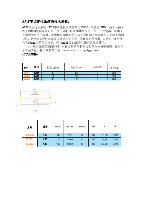
AMF 零点定位系统,K20零点定位系统拉紧力20KN ,夹紧力55KN 。
两个及两个以上的K20定位系统可用于加工500公斤到2000公斤的工件。
尺寸紧凑,可用于夹紧中等尺寸的零件。
可提供自动化型号,与工业机器人配套使用。
采用不锈钢材料,定位接头可任意角度安装进入定位孔,没有滚珠保持器,大钢珠,高刚性,具有10mm 误差自动校正。
可与AMF 其他液压/气压夹具配套使用。
用于减少更换工装的时间,可在金属切削和非切削等各领域中使用,也可用于食品工业,化工和制药工业。
尺寸及规格:
货号 型号 拉紧力(kN)
夹紧力(kN)
自动除尘
重量Kg 3051K10 8 25 √ 0,9 3028K20 17 55 √ 2,6 3028
K40
30
105
√
6,6
货号
型号 dia.D dia.DB dia.DN HA K R
305193 K10 78 77,5 22 30 16,50 G1/8 302851 K20 112 110,0 32 50 28,25 G1/4 302893
K40
148
146,0
40
62
32,50
G1/4
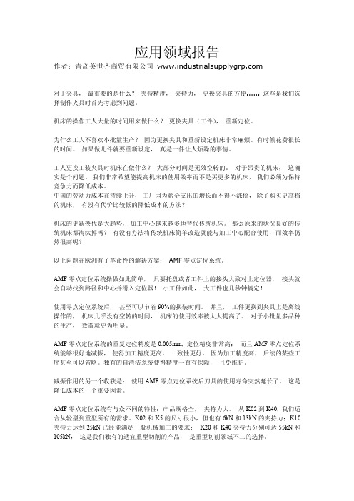
工件
定位和夹紧
夹具托盘
通过零点定位系
统定位和夹紧
零点定位单元
机床工作台。
零点定位系统应用报告
应用领域报告作者:青岛英世齐商贸有限公司对于夹具,最重要的是什么?夹持精度,夹持力,更换夹具的方便......这些是我们选择制作夹具时首先考虑到问题。
机床的操作工人大量的时间用来做什么?更换夹具(工件),重新定位。
为什么工人不喜欢小批量生产?因为更换夹具和重新设定机床非常麻烦。
有时候花费很长的时间。
如果做几件就要重新设定,真是一件让人烦躁的事情。
工人更换工装夹具时机床在做什么?大部分时间是无效空转的。
对于昂贵的机床,这确实是个问题。
我们非常希望能提高机床的使用效率而不是买更多的机床,我们必须为保持竞争力而降低成本。
中国的劳动力成本在持续上升,工厂因为薪金支出的增长而不得不涨价,除了购买更高档的机床,有没有代价比较低的降低成本的方法?机床的更新换代是大趋势,加工中心越来越多地替代传统机床。
那么原来的状况良好的传统机床都淘汰掉吗?有没有办法将传统机床简单改造就能与加工中心配合使用,而效率仍然很高呢?以上问题在欧洲有了革命性的解决方案:AMF零点定位系统。
AMF零点定位系统操做如此简单,只要托盘或者工件上的接头大致对上定位器,接头就会自动找到路径和中心并滑入定位器!小工件如此,大工件也几秒钟搞定!使用零点定位系统后,甚至可以节省90%的换装时间。
并且,工件更换到夹具上是离线操作的,机床几乎没有空转的时间,机床的使用效率被大大提高了。
对于小批量多品种的生产,效益就更为明显。
AMF零点定位系统的重复定位精度是0.005mm,定位精度非常高;而且AMF零点定位系统能够很好地减振,使得加工精度更高,一致性更好。
因为加工精度高,后续的某些工序甚至可以省略。
独有的自清洁系统使得精度一直有保障,且免维护。
减振作用的另一个收获是:使用AMF零点定位系统后刀具的使用寿命突然延长了,这是降低成本的一个重要因素。
AMF零点定位系统有与众不同的特性:产品规格全,夹持力大。
从K02到K40,我们适合从轻型到重型所有的需求。
K02和K5的尺寸很小,但也有6kN和13kN的夹持力;K10夹持力达到25kN已经能满足一般机械加工的要求;K20和K40夹持力分别可达55kN和105kN,这是我们独有的适宜重型切削的产品,是重型切削领域不二的选择。
上海安钧AMF型电磁流量计技术描述

上海安钧AMF 型电磁流量计技术描述一、AMF 型电磁流量计工作原理电磁流量计的工作原理基于法拉第电磁感应定律。
当一个导体在磁场内运动,在与磁场方向、运动方向相互垂直方向的导体两端,会有感应电动势产生。
电动势的大小与导体运动速度和磁感应强度大小成正比。
在图1-1中,当导电流体以平均流速V (s m /),通过装有一对测量电极的一根内径为D (m )的绝缘管子流动时,并且该管子处于一个均匀的磁感应强度为B (T )的磁场中。
那么,在一对电极上就会感应出垂直于磁场和流动方向的电动势(E )。
由电磁感应定律,可写做(1)式: V D kB E ⋅⋅=(V ) ………………(1) 式中k 是比例系数。
通常,体积流量可以写作V Dq4π=(s m /) (2)由公式(1)和(2)可得到:)(43s m BE k D q v π= (3)因此电动势可表示为:)(q 4v V D kBE π=………………………(4) 当B 是个常数时,公式(3)中A Bk D =14π,公式(3)改写为: )/(3s m AE q v =可见,流量q 与电动势E 成正比。
U图1.1 电磁流量计工作原理图1-2 转换器电路结构产品用途与适用范围1.1 特点:■可编程频率低频矩形波励磁,提高了流量测量的稳定性,功率损耗低;■采用新型含有FLASH存贮器的16位超低功耗微处理器,集成度高,运算速度快,计算精度高。
■全数字量处理,抗干扰能力强,测量可靠;■超低EMI开关电源,适用电源电压变化范围大,效率高,温升小。
抗EMC性能好;■中英文菜单操作,使用方便,操作简单,易学易懂;■高清晰度背光、宽温型LCD显示;■能进行双向流量测量、双向总量累计。
具有量程自动切换功能,更有效地提高了模拟电流和频率输出的测量精度,特别适用于昼夜流量范围变化大并需要发出控制信号的场合。
流量测量范围度可达50 : 1。
■内部有三个积算器,分别显示正向累计量、反向累计量及累计差值积算量,方便于流体计量和贸易交接。
GSM GPRS GPS定位追踪器 说明书

GSM/GPRS/GPS定位追踪器使用手册序言.非常感谢您购买我们的GPS定位跟踪器。
使用手册将详细的说明如何操作本产品。
因此务必请您在使用产品前认真的阅读本份使用手册。
如有更改,恕不另行通知。
每次更改将统一在最新的一次产品销售中发布。
生产商对于使用手册其中的过失和疏漏不承担法律责任。
目录1简介----------------------------------------------------------------------------------3 2应用领域----------------------------------------------------------------------------------3 3硬件3.1前面----------------------------------------------------------------------------------------33.2后面-----------------------------------------------------------------------------------------33.3侧面---------------------------------------------------------------------------------------33.4底面-----------------------------------------------------------------------------------------43.5内部----------------------------------------------------------------------------------------4 4规格描述-------------------------------------------------------------------------------------4 5使用说明5.1SIM卡的放置--------------------------------------------------------------------------------55.2电池和充电器------------------------------------------------------------------------------55.3设备启动------------------------------------------------------------------------------------65.4初始化设置----------------------------------------------------------------------------65.5设置密码-------------------------------------------------------------------------------------65.6授权设置------------------------------------------------------------------------------------75.7单次定位-------------------------------------------------------------------------------------75.8自动连续定位-------------------------------------------------------------------------------75.9监听----------------------------------------------------------------------------------------7监听模式””的转换----------------------------------------------75.10“定位模式定位模式””和“监听模式5.11电子栅栏--------------------------------------------------------------------------------85.12移位报警------------------------------------------------------------------------------85.13超速报警---------------------------------------------------------------------------------85.14IMEI码查询---------------------------------------------------------------------------95.15紧急报警--------------------------------------------------------------------------------95.16底电报警------------------------------------------------------------------------------95.17隐藏号码定位-------------------------------------------------------------------------95.18设置平台短信中心号--------------------------------------------------------------------95.19GPRS的设置---------------------------------------------------------------------------9 6警告注意------------------------------------------------------------------------11 7故障处理方法-----------------------------------------------------------------------111简介本产品基于GSM/GPS 网络和GPS 卫星定位系统,通过短信息或互联系对远程目标进行定位或监控.。
AMF25中文说明书(全)
按钮和LEDs----------------------------------------------------------------------------------50
显示菜单------------------------------------------------------------------------------------51
怎么看测量的数据?--------------------------------------------------------------------------51
包里有什么?-------------------------------------------------------------------------------6
IL-RA15遥控信号器--------------------------------------------------------------------------6
发电机保护------- -------------------------------------------------------------------------37市电故障-----------------------------------------------------------------------------------39
模拟输入-----------------------------------------------------------------------------------29
liise品牌发电机控制器amf 中文说明书
IL-NT-AMF20/25 中文说明书目录:目录 (2)一般准则 (5)本手册介绍了什么? (5)!!警告!! (5)标志符号 (5)文本 (6)一般说明 (7)控制系统的说明(以及所有的附件) (7)包装里面有什么? (7)IL-NT RS232 通讯插卡.......... .. (7)IL-NT RS232-485 通讯插卡. .............................................................................................................................................. ..11 IL-NT S-USB USB 通讯服务插卡 (11)IB-Lite 以太网通讯插卡. (12)IL-NT AOUT8 测量仪表驱动模块 (13)IL-NT BIO8 交替二进制输入/输出模块 (15)IL-NT RD 远程显示软件 (16)IGL – RA15远程信号器 (16)IG-IOM/PTM 模块 (17)IG-IB网桥 (18)IL-NT 终端.... . (18)IL-NT 端子和面板......... (18)安装 (20)控制器安装 (19)推荐使用的线路图.. (21)AMF 线路图 (21)软件应用支持 (22)电流接触器(设置点MCB逻辑=“通-关”) (22)ATS两个状态位置(设置点MCB逻辑=“通-合”) (21)ATS三个状态位置(设置点MCB逻辑=“通-断”) (22)准备工作的开始 (24)如何安装 (24)电流测量 (27)电压测量和发电机连接类型 (28)模拟量输入 (31)RS485 连接 (37)扩展模块(CAN 总线)连接 (39)输入和输出 (40)IL-NT二进制输入—默认 (40)二进制输入—列表 (40)二进制输出—列表 (43)模拟量输入 (54)模拟量输出 (54)设定点................................................................................................................................................................................. . (55)密码 (55)基本设定 (56)发动机参数 (61)发动机保护 (66)发电机保护 (69)AMF 设定 (73)日期/时间 (78)传感器规格 (80)*扩展I/O (80)短信/邮件 (81)*ECU---控制引擎支持 (83)确定ECU 配置 (84)从ECU 读参数 (84)从ECU 读出的配置信息 (85)模拟量输入 (85)连接说明 (85)传感器说明 (88)传感器校正 (88)传感器默认曲线 (88)功能描述 (89)“关”模式 (89)“手动”模式 (89)“自动”模式 (90)测试模式 (91)断路器计时 (92)报警管理 (94)传感器故障(FLS) (94)警告(WRN) (94)停机(SD) (94)市电失败 (MF) (94)电压相序监测 (95)发电机组工作状态 (98)报警一览表 (99)历史文档 (100)初始化屏幕 (101)顾客标准显示 (101)软件版本显示 (101)语言屏幕 (102)用户界面屏幕 (102)远程控制和数据记录 (102)直接连接到电脑 (102)电脑软件—LiteEdit (104)Modbus 协议 (104)远程通讯 (111)互联网连接 (111)推荐ISDN调制解调器 (111)推荐GSM调制解调器 (111)手机SIM卡设置 (111)IL-NT-RD远程监控软件 (112)一般说明 (112)警告............................................................................................................................................................................... .. (112)IL-NT-RD软件安装..................................................................................................................................................... (112)IL-NT-RD数据线............................................................................................................................................................ (113)功能描述 (116)Sw兼容性 (116)维护保养 (117)备用电池更换 (117)详细的技术参数 (119)输入/输出概述 (119)发电机保护 (119)语言支持 (120)电源 (120)*低温型 (120)技术数据 (121)尺寸规格和重量 (121)发电机 (122)二进制输入和输出 (122)模拟量输入 (122)速度传感器输入 (122)D+端子 (123)*CAN总线接口 (123)IL-NT RS232接口(可选择卡) (123)IL-NT RS232-485接口(可选择卡) (124)IL-NT S-USB接口(可选择卡) (124)IL-NT AOUT8接口(可选择卡) (124)IL-NT BIO8接口(可选择卡) (124)IGS-PTM (125)IGL-RA15 (125)IG-IB (126)一般准则本手册介绍了什么?重要安全说明保存此命令-----在安装过程中应遵循包含本手册IL -Nt系列控制器的重要操作指南和lnteli 发电机组控制器。
- 1、下载文档前请自行甄别文档内容的完整性,平台不提供额外的编辑、内容补充、找答案等附加服务。
- 2、"仅部分预览"的文档,不可在线预览部分如存在完整性等问题,可反馈申请退款(可完整预览的文档不适用该条件!)。
- 3、如文档侵犯您的权益,请联系客服反馈,我们会尽快为您处理(人工客服工作时间:9:00-18:30)。
一、概述:
1、产品名称:AMF 零点定位系统及附件
2、产品型号:K10.3,K20,K20.3
二、产品结构
1、锁紧钢珠
2、安装螺栓
3、螺纹销(辅助零点定位单元的安装,未在图中标出)
4、螺纹销,用于不使用自动除屑的应用
5、螺纹销,用于使用自动除屑的应用
6、安装工具
AMF零点定位系统使用说明书
三、产品安装及使用
(一)零点定位接头凹头的安装
不要讲安装工具⑥去掉
去掉保护橡胶圈
清洁安装孔,及安装表面,并涂入润滑
脂,将零点定位单元凹头装为安装孔,
并安装平
旋紧安装螺栓旋紧螺栓时使用扭矩扳手,M6,扭矩8Nm拆卸安装工具⑥
将螺纹销④或⑤旋入零点定位接头凹头内孔底部的螺纹孔,并用适合于不锈钢的胶粘结。
(二)零点定位接头凸头的安装
1、需要更换的夹具托盘
2、紧固螺栓
3、零点定位接头凸头
4、扭矩扳手K20M12扭矩120Nm 零点定位接头凸头(1)
单向定位接头凸头(2)
紧固定位接头凸头(3)
K10
M8
34Nm
扭矩
䴬⛯ᇐփ䬶Ⲻᑮ⭞࠼ᐹ
䘉⿽ᇊս䬰࠶ᐳ䘲⭘Ҿа㡜⭏ӗ⧟ຳDŽ
䴦⛩ᇊս䬰䎧ࡠ䲀ࡦ;ˈ<ᯩੁ㠚⭡ᓖⲴ⭘ˈᡀѪ৲㘳ส⛩˗অੁᇊս䬰ਚ䲀ࡦ䖜ᯩੁⲴ㠚⭡ᓖˈ
㘼㍗പᇊս䬰ਚ䎧ࡠ໎࣐ཀྵ㍗࣋Ⲵ⭘ˈ䘉ṧਟԕ؍䇱ᮤњᢈⴈⲴᆼޘᇊսˈ
䚯ݽ䗷ᇊսDŽঅੁᇊս䬰䴦⛩ᇊս䬰㍗പᇊս䬰
3
3
1
2
12
3ᇐփ䬶ᆿ㻻ᆊⲺࣖᐛተሮ
ተሮ
Dia.D1Dia.M S1S2K027,17M 53,614K510,00M 62,512K1015,00M 83,516K2025,00M125,523K40
25,00
M16
5,5
30
ഴ⽰
മѝᱮ⽪Ⲵᱟᇊս䬰઼㍗പ㷪ṃDŽ
注意:
单向定位接头的两个凸点连线需要垂直于零点定位接头和单向定位接头的连线方向。
公差要求:
A=零点定位接头凸头到单向定位接头凸头的距离+/-0.01mm
B=零点定位接头凸头到紧固定位接头凸头的距离+/-0.03mm
1、使用的压缩空气必须无水,并进行油雾润滑,润滑标准(~2-5ml/m³),使用DIN51524-2VG 32润滑油或相近的润滑油;
2、适当的维护有助于保证零点定位系统的长期使用。
在日常使用时请注意进行维护。
每天的维护:清理零点定位系统的铁屑,可以使用气枪或者真空吸屑器每月的维护:①肉眼观察零点定位系统的状态
②检查定位单元的紧固螺栓以及定位接头的紧固螺栓③检查零点定位系统的功能。
每年的维护:
K20气压型零点定位系统需要每年或者每15万次进行以下主动维护:①检查零点定位单元的密封圈②检查零点定位单元的弹簧
用户可根据实际生产情况进行强制、预防性更换这些元件。
四、使用与维护。