harmonized charls 中文使用说明
恒华水准计算与管理软件说明书

恒华测绘软件系列恒华水准计算与管理软件Version 4.0北京恒华集团2008.3前言 (4)第一章 HLevel概述 (5)1.1 系统简介 (5)1.2 安装及运行 (5)1.3 快速入门 (6)第二章计算、平差 (10)2.1 测站数据输入 (10)2.2 平差、求高程 (11)2.3 参数设置 (11)第三章工具 (15)3.1 按两种方式平差 (15)3.2观测数据乘系数 (15)3.3 统计分析 (16)3.4 解除平差 (16)3.5 分析错误 (16)3.6 楼号编辑器 (16)3.7 查看现有楼号 (17)3.8 电子水准数据转换 (17)第四章 HLevelManager概述 (18)4.1 系统简介 (18)4.2 安装及运行 (18)4.3 快速入门 (19)第五章计算沉降 (25)5.1 导入数据 (25)5.2 计算沉降 (25)5.3 搜索变化最大点 (25)第六章报表、图形输出 (27)6.1 单点数据报表 (27)6.2 日期数据报表 (29)6.3 最后统计分析数据 (30)第七章编辑功能 (39)7.1 单点复制功能 (39)7.2 日期复制功能 (39)7.3 批量修改点名 (39)7.4 批量修改日期 (39)7.5 直接快速修改数据 (39)7.6 相邻表编辑功能 (39)7.7 数据库备份/还原功能 (40)7.8 重新布点功能 (40)7.9 部分日期导出功能 (40)7.10 文本文件导入功能 (40)7.11 批量删除点 (40)7.12 批量删除日期 (41)第八章设置 (42)8.1 显示设置 (42)8.2 页眉页脚设置 (42)8.3 项目设置 (43)8.4 图形输出设置 (43)附录1 HLevel的文件组织 (45)1 HLevel (45)2 HLevelManager (45)附录2 所附实例文件目录 (45)附录3 回归分析函数原型 (45)前言“恒华水准计算与管理软件”简称(HLevel计算部分/HLevelManager管理部分)。
哈德威录波器规约使用说明

哈德威录波器规约一.规约简介使用范围:9793接入哈德威录波器、北京电研录波器、浪拜迪录波器。
只用于CPU3。
通讯通讯介质:网络二.规约转换内容●当前功能本规约具有FTP方式读录波器波形数据功能。
●修改记录三.TCP连接配置端口号= 0000 :没有使用服务器IP = 000.000.000.000 :录波器的IP地址前三位。
最低位由装置的映射地址(1.00)、可变相关信息决定(2.00,3.00)。
四.规约相关信息●当前信息用户名:STRING="replay":FTP登录时的用户名口令:STRING="hathaway":FTP登录时的口令FTP路径:STRING="DFR_Comtrade/":波形文件所在的目录故障记录文件名:STRING="message":故障记录表的文件名●修改记录五.装置相关信息●当前信息●修改记录六.可变装置相关信息●当前信息IP=8:该装置对应的ip地址最低位。
文件目录=VI_11:指定装置的波形文件存储位置。
波形间延时=120:需要经过多长时间的延时再要下一个。
●修改记录V2.66版新增:波形间延时=120:需要经过多长时间的延时再要下一个。
七.需要注意的问题1.用户名:STRING="replay" FTP登录时的用户名口令:STRING="hathaway" FTP登录时的口令FTP路径:STRING="DFR_Comtrade/" 波形文件所在的目录故障记录文件名:STRING="message" 故障记录表的文件名2.录波器V1.00的ip地址=添加TCP规约时设置的高三个字节和装置的影射地址组成。
例:添加TCP端口时ip设置为:198.87.120.0添加装置时设置的映射地址为121录波器的ip地址=198.87.120.1213.录波器V2.00用于将HA THAW AY的每一个单元作为一个装置。
Hart 菜单中英文对照

1. PROCESS VARIABLES 过程变量(只看) 1.Press过程变量 2. %range百分比量程 3. AO1 out模拟输出 4. Snsr tempe传感器温度 5. static 6.engr unit7.engr disp1. TEST DEVICE 测试设备1. Seft 自检2. Statics 状态2. DIAG/ SERVICE 2. LOOP TEST 回路测试1. 4mA2. 20mA3. Other4. END诊断和维修1.RE-RANGE 重设量程 ( 1.Keypad input 键区输入2.Apply values 实际输入 )3.CALIBRATION 校准 2.Trim analog output 修整模拟输出 ( 1.D/A trim 数/模刻度修整 2. Scaled D/A trim数/模刻度修整)3.Sensor trim 传感器修整 1. ZeroTrim 零点微调 2. Press过程变量 3. Lower Sensor Trim传感器下限微调1.Tag 位号4. Upper Sensor Trim传感器上限微调5. Sensor Trim Points传感器微调点6.clear snsr trim2.Unit 单位3.RE-RANGE 重设量程( 1.Keypad input 键区输入 2.Apply values 实际输入 )3. BASIC SETUP4. Device information 设备信息基本设置 5.Transfer function 变送器特性 Linear/Sq root线性/开方6.Damp 阻尼7.Low cut 1. %range百分比量程8.cut mode 2. Press过程变量1.PRES SENSOR压力传感器 3. Unit 1. ZeroTrim 零点微调2. Press过程变量3. Lower Sensor Trim传感器下限微调1. DEVICE SETUP 设备设置 1. SENSORS传感器4. Sensor trim 传感器修整 4. Upper Sensor Trim传感器上限微调5. Sensor Trim Points传感器微调点6.clear snsr trim1.offline 离线2. Pres 压力2. TEMP SENSOR传感器温度 (1.Sensor Temp 传感器温度 2. Amp temp3.snsr temp unit )2.online 在线3. AO1 out 模拟输出4. DETAILED SETUP 3.Statics pres Sensor (1.Statics pres 2.Statics pres unit )3.utility4. LRV 量程下限详细设置1.Process variables 过程变量2. RE-RANGE 重设量程3. Unit 单位4. Transfer function 变送器特性 Linear/Sq root线性/开方4.Hart Diagnostics 诊断5. URV 量程上限 2. SIGNAL CONDITION信号条件 5. Damp 阻尼 6. Low cut 7. cut mode 8.Bi-dir mode 9.H2Ocutliselect1. PROCESS VARIABLES (1. Press过程变量2. %range百分比量程3. AO1 out模拟输出4. Snsr tempe传感器温度 5. static 6.engr unit 7.engr disp)过程变量3. OUTPUT CONDITION输出条件 2. ANALOG OUTPUT 1.Loop test回路测试(4mA 20mA Other END) 2. D/A trim 数/模刻度修整 3.Scaled D/A trim数/模刻度修整(1.proceed 2.change )模拟输出 4.Auto recover 5.AO Lower Limit% 5.AO Upper Limit%3. AO1 Alarm type 模拟输出报警类型4. HART OUTPUT Hart 输出 (1.Poll Address波尔地址 2.Number request preambles 需求号码 3. Burst mode突发模式 4.Burst option突发选项)1.Display mode (1.Normal% er set 3. User set &% 4.Input press 5.Input press&% )4.Display condition 2.Display fnctn3.Engr disp range1. FIELD DEVICE INFO现场设备信息 1.Tag位号2.Date日期3.Descriptor描述4.Message信息5.Model型号6.Write protect写保护5. DEVICE INFORMATION7.Local Keys 本机键(ENABLE-允许 DISABLE-禁止) 8.Revision 9.Final assy #--Device ID设备信息1. Measurement Type 测量类型2. mod. Config. Type 模块组态类型3 .Isolator Material 隔离器材质 4. Fill Type 法兰类型2.SENSOR INFO传感器信息 5 .Proc. Conn. Type 过程连接类型 6. Proc. Conn. Materia 过程连接材质.O-Ring Material 模片材质 8. Drain/Vent Material 排液/排气材质3. SELF TEST 自检1.Manufacturer2.Model3.Unit4.LSL5. USL5. Review审核6.Min span7.LRV 8.URV。
海伯核采样器操作手册说明书
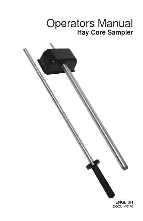
After obtaining enough samples, remove the bag from the steel cup, press the excessive air out from the plastic bag and secure it tightly. Add necessary markings (date, bale, crop, name, number) and store it properly. [cool place with non-fluctuating temperature]
Tests have shown that Hay Core Sampler’s cutting tip stays sharp for about 500 full depth core samples taken from dense round hay bale. You can also use drill to sharpen the cutting tip but use special care when sharpening the tip with the help of drill.
Cleaning and Storage After use clean the hay core sampler with a damp cloth and rub it dry. Store in dry place, preferably inside where the temperature stays above 32°F / 0°C and doesn’t fluctuate much.
USA
Do not wear any loose clothing when using Hay Core Sampler. Be aware that the cutting tip is very sharp, especially when using the cleaning rod. Use the rubber tip cover to protect the user and the tip when not using the item.
朗达尔医疗通信系统产品说明书

GESecurity Sound and Communicationsimagination at workProduct GuideTelligence ™Voice-over-IPPatient-Staff Communication SystemTelligence BridgeFacility LANTelligence LAN Hallway Network Room NetworkRoom Network Peripheral NetworkPeripheral NetworkStaff ConsoleAnnunciatorDomeLights Smart Station Smart StationPresence stations and lavatory stations PowerSwitchStation GatewayDesigned to meet the needs of your facility...ColorTouch ™ User Interface Patient-staff communications at your fingertips.HearingAid ™ AudioFor crystal clear voice communication.Choice ™ Programming You control system operation – it doesn’t control you.NiteLite ™ Station Illumination No more fumbling in the dark.Infinity ™ Dome Lights One light. Infinite possibilities.PC Connect ™ SoftwareA powerful software suite that takes system usability to a new level.••••••™HearingAid™ audiofor crystal clear conversation...Only Telligence has HearingAid technology, which allows staff to adjust talk and listen volume levels for each patient conversation. This ensures that conversations are understandable and productive. In addition to manual volume controls, HearingAid technology also incorporates automatic noise and echo cancellation, which suppresses non-essential noise to provide crystal clear voice communication with little background noise.ColorTouch ™ VoIP Staff ConsoleData Sheet 85100-0103The ColorTouch ™ VoIP Staff Consolevisually displays incoming calls fromstations and connected healthcareequipment, and provides a meansfor the operator to prioritize andrespond to selected events. As anintercom device, it provides audiblesignaling functions and facilitatestwo-way full-duplex staff/patient andstaff/staff communications.HC-CONSOLE ColorTouch ™ VoIP Staff Console ColorTouch ™ VoIP AnnunciatorData Sheet 85100-0110The ColorTouch ™ VoIP Annunciator of-fers all the performance-rich featuresof the Staff Console in a convenientwall-mounted configuration. Ideallysuited for hallways and staffrooms,it provides a bright, easy-to-see Col-orTouch LCD screen for one-touchcall answering, audible signalingfunctions, and two-way full-duplexcommunications. The annunciatormay be set to filter calls by type, soonly the most appropriate messagesreach its installed location.HC-ANNUN ColorTouch ™ VoIP Annunciator Adjustable viewing angle Compact desktop design Hands-free speakerphone Privacy handset HearingAid ™ audio featuresFull duplex speaker and microphone Hands-free audio Large LCD touchscreen HearingAid ™ audio features Call filteringprovide NiteLite™ on-board lighting, darkened rooms.Smart Patient and Staff/Duty StationsData Sheet 85100-0104Smart Patient Stations provide sepa-rate 18-pin receptacles for the con-nection of DuraPin ™ pillow speakersand two ¼" (0.64 mm) receptaclesthat can be programmed to accepteither an input from auxiliary equip-ment, or a bed call cord. Smart Staff/Duty Stations (HC-DUTY) have no bedconnections or call cord jacks.HC-PSTN1Single Smart Patient Station HC-PSTN2Dual Smart Patient Station HC-DUTY Smart Staff/Duty Station Smart Patient Stations with BedConnect ™Data Sheet 85100-0105Smart Patient Stations with Bed-Connect ™ provide convenient on-board 37-pin connectors for side-railcommunications with compatibleelectronic beds such as those manu-factured by Hill-Rom ® and Stryker ®.These stations have separate 18-pinreceptacles for the connection ofDuraPin ™ pillow speakers and two¼" (0.64 mm) receptacles that can beconfigured to accept an input fromauxiliary equipment, or a call cord.HC-PSTN1-BED Single Smart Patient Station with BedConnect ™HC-PSTN2-BED Dual Smart Patient Station with BedConnect™HearingAid ™ noise and echo cancellation Choice ™ configurable buttons NiteLite ™ on-board lighting Cleaning mode reduces accidental calls HearingAid ™ noise and echo cancellation Choice ™ configurable buttons NiteLite ™ on-board lighting Cleaning mode reducesaccidental callsPeripheral Stations Data Sheet 85100-0107Peripheral Stations are available in two types, push/pull stations (HC-PP series) and pushbutton stations(HC-PB). These Peripheral Stations are supervised initiating devices that provide patient room call-for-assis-tance indication to the patient-staff communications system. When aPeripheral Station is activated, vi-sual indication of the call displays atthe dome light associated with the patient room, and an appropriate call indication registers on the Col-orTouch ™ VoIP Staff Console, as well as any installed ColorTouch ™ VoIP Annunciators. An LED also illuminates on the front of the station until the call is canceled.Models come with field-configurablebuttons used for placing patient calls,requesting staff assistance, indicat-ing staff presence, or signaling asentinel event. There are also mod-els that include a relay for externalequipment, or an input for a roomsmoke detector. Peripheral Stationsmay also be fitted with optional pullcords, which can be used to operatethe devices.HC-PP3-PRES 3-Button Push/Pull Station, PresenceHC-PB2-CALLIN 2-Button Station, Staff Normal Call w/Smoke Input HC-PB2-CALLR 2-Button Station, Staff Normal Call w/Relay HC-PB3-CANCEL 3-Button Station, Remote CancelHC-PB2-CODE 2-Button Station, Code BlueHC-PB2-EMERG 2-Button Station, Staff EmergencyHC-PP2-LAV 2-Button Push/Pull Station, LavatoryChoice ™ configurable buttons NiteLite ™ on-board lighting Optional pull cord operation Dedicated LEDindicators Relay models available Optional two-level call priority on lavatory stationsAuxiliary Input & Call Cord StationsData Sheet 85100-0109Auxiliary Input and Call Cord Stations are addressable initiating devices that provide bedside call-for-assis-tance indication to the patient-staff communications system. When an Auxiliary Input or Call Cord Station is activated, visual indication of the call displays at the dome light associated with the patient room, and an ap-propriate call indication registers on the ColorTouch ™ VoIP Staff Console, as well as any installed ColorTouch ™ VoIP Annunciators. An LED also il-luminates on the front of the station until the call is canceled.Auxiliary Input Stations are typically used for the connection of medical equipment. Each device provides two inputs at dedicated ¼" jacks. Call Cord Stations provide one ¼" jack input to support a single call cord. They include a dedicated CANCEL button for each cord.HC-AUX2 Dual Auxiliary Input StationHC-AUX2-ISO Isolated Dual Auxiliary Input Station HC-CCSTN Single Call Cord StationChoice ™ configurable buttons NiteLite ™ on-board lighting Call cord connectors Dedicated LED indicators Isolated model available Supports up to 20 uniquenameable inputsOnly Telligence unleashes the power of Choice ™ Programmable Technology, putting you in control of each room with fully customizable station buttons and patient monitor alarms. The revolution-ary Infinity ™ Dome Light, with its exclu-sive multicolor LED design, lets you decide how each nurse call event is dis-played, making it easy to distin-guish between sentinel events and routine calls.Normal bed call Emergency Staff assist Monitor alarm Code Blue (flashing)Infinity ™ Series LED dome lights provide bright, easy-to-see visual annunciation that speeds response time and increases caregiver ef-ficiency. These devices are typically installed in corridors and outside pa-tient rooms to provide staff with visual cues as to the origin of calls placed on the system. The light color and flash rate indicates the type and priority of the call. Models are available with one, two, or four light sections.Thanks to advanced LED technology, each light section of Infinity Series LED dome lights are software-con-figurable to illuminate seven colors. This breakthrough capability means that one device model can serve many different purposes. For audible annunciation, a model is also avail-able with an integrated buzzer. This too may be programmed to signal at different rates depending on the nature of the call.HC-CL1-REDLED Dome/Zone Light, 1 Section HC-CL2Infinity ™ LED Dome/Zone Light, 2 Sections HC-CL4Infinity ™ LED Dome/Zone Light, 4 Sections HC-CL4-SUPV LED Supervision Module w/BuzzerSeven colors from a single light section Fully programmable Configurable flash rates and patterns Integrated buzzer available Advanced LED technologyGE Security call cords and DuraPin ™ pillow speakers are sturdy, resilient momentary contact devices used toinitiate calls from patient stations. Call cords plug into the patient sta-tion with a ¼-inch connector. Simple pushbutton operation places a call on the system. DuraPin ™ Pillow speak-ers feature patient-staff communica-tions as well as television control, and room lighting operation. Consult the data sheet for available models.Bed Receptacle, Single 37-Pin The Bed Receptacle-Single 37-Pin connector acts as an interface be-tween compatible GE Security pa-tient-staff communications systems and Hill-Rom ® or Stryker ® electronicbeds. It is specifically used to en-able side-rail communications with the patient-staff communications system.HC-BID-SS37 Bed Receptacle-Single 37-PinOptional numeric keypad available TV controls compatible with all major brands Compatible with Hill-Rom ® and Stryker ® beds Compatible with Hill-Rom ® and Stryker ® bedsPowerSwitch ™Data Sheet 85100-0101The Telligence PowerSwitch ™ is an Ethernet ® communication interface and power supply for all IP devices residing on the Telligence ™ patient-staff communications network. It interconnects with system compo-nents by means of standard network wiring, cabling, and connectors. An AC power source is required.HC-IPSWITCH8 Telligence PowerSwitch ™ Station Gateway ™Data Sheet 85100-0100The Telligence Station Gateway ™ facilitates the use of non-IP address-able stations on the Telligence ™ IP network. Each gateway supports up to 16 Smart Stations, including single and dual patient stations, and staff stations. Device wiring is via industry standard Cat 5/5e/6 cable. An AC power source is required.HC-GTWY1 Telligence Station Gateway ™Supports up to 16 smart stations Standard snap-in connectors 19" Rack mountableSupplies power and interconnection for all IP devices Eight 100 Mps Ethernet switch ports available Standard Cat 5/5e/6 cabling 19" Rack mountableSoftwareTelligence supports a powerful suite of software applications that offer centralized system management and comprehensive reporting. Allapplications can share data through a common database and interface. This interface represents a single integrated platform for communicat-ing with wireless devices, generating management reports, and providing a wide range of valuable features, tools, and utilities.PC Assignments provides easy assign-ment of staff, wireless devices, and patientbeds so patient calls are automatically delivered to the right caregivers.MapView ™ and ListView ™ provide con-venient graphical and list-based details concerning Telligence system Board ™ is an electronic whiteboard that displays real-time staff and patient information.PC Reporting measures response times to patient calls and other system activ-ity, and can even schedule reports forautomatic email delivery.PC Messaging provides convenient text messaging to mobile devices like pag-ers, wireless telephones and Vocera ™ pendantsMobility Suite delivers wireless system connectivity plus PC Assignments and PC Messaging , for a convenient all-in-onesolution.ADT Bridge allows HL7 import of key pa-tient information to the SQL database for display with Telligence applications.Innovative Clients Intuitive browser screens Powerful system connectivity Centralizedsystemmanagement,comprehensivereporting.GESecuritySound and CommunicationsU.S.T 888 GE SECURITYF 800 483 2495CanadaT 519 376 2430F 519 376 7258© 2006 General Electric CompanyAll Rights ReservedTelligence, ColorTouch, Station Gateway,PowerSwitch, HearingAid, Choice, NiteLite,Infinity, MapView, NetBoard, DuraPin, andBedConnect are trademarks of GE Security,Inc. Hill-Rom is a trademark of HillenbrandIndustries. Vocera is a trademark ofVocera Communications. Stryker is atrademark of Stryker Corporation. Ethernetis a trademark of Xerox Corporation.imagination at workP/N: 85100-0217。
harmonized charls documentation

harmonized charls documentation Harmonized Charles Documentation: Ensuring Standardization and Efficiency in Global TradeIntroduction:In today's interconnected global economy, international trade plays a vital role in driving economic growth and development. However, conducting cross-border trade can be a complex and challenging process due to various legal and regulatory requirements. To address these challenges and promote standardization and efficiency in global trade, the concept of harmonized Charles documentation has emerged. In this article, we will explore the importance of harmonized Charles documentation, its benefits, and the step-by-step process of implementing it.1. The Need for Harmonized Charles Documentation:International trade involves multiple parties, including exporters, importers, customs officials, and shipping companies. Each party needs to exchange information and documents accurately and efficiently to facilitate the smooth movement of goods acrossborders. Harmonized Charles documentation serves as a global standard for documenting trade transactions, ensuring consistency, transparency, and interoperability in the exchange of information.2. Benefits of Harmonized Charles Documentation:2.1 Standardization:Harmonized Charles documentation provides a standardized format for documenting trade transactions, including order details, product descriptions, quantities, values, and shipping instructions. The standardized format ensures consistency across different countries and enables seamless data exchange between trading partners, reducing errors and delays.2.2 Efficiency:By standardizing trade documentation, the process becomes more streamlined, reducing the time and effort required for data entry, verification, and processing. This increased efficiency benefits all parties involved, resulting in quicker customs clearance and faster delivery of goods.2.3 Reduced Costs:Efficient documentation processes lead to cost savings in terms of time, labor, and resources. By eliminating manual data entry and reducing errors, the need for costly rework and delays is minimized. Harmonized Charles documentation also reduces the risk of penalties and fines resulting from non-compliance with trade regulations.3. Implementing Harmonized Charles Documentation:Implementing harmonized Charles documentation involves a step-by-step process that requires collaboration between different stakeholders in the trade ecosystem. Here are the key steps involved:3.1 Stakeholder Engagement:Bringing all relevant stakeholders on board is essential for successful implementation. This includes exporters, importers, freight forwarders, customs authorities, and trade facilitation organizations. Engaging these stakeholders from the beginning ensures their understanding and commitment to the harmonization process.3.2 Training and Capacity Building:To effectively implement harmonized Charles documentation, adequate training and capacity building programs are crucial. This includes educating the stakeholders on the standardized formats, data fields, and procedures required for trade documentation. Training programs can be conducted by trade associations, customs authorities, or specialized training institutes.3.3 Integration of Systems:To enable seamless data exchange, various IT systems used by the stakeholders need to be integrated. This involves developing interfaces and protocols for data transmission, ensuring compatibility and interoperability among different systems. Trade facilitation organizations often play a key role in coordinating this integration process.3.4 Compliance and Adoption:Successful implementation of harmonized Charles documentation requires widespread adoption and compliance by all stakeholders. Customs authorities need to update their regulations and procedures to align with the standardized documentation requirements. Ensuring awareness and compliance among thetrading community is crucial for reaping the full benefits of harmonized Charles documentation.Conclusion:Harmonized Charles documentation undeniably plays a significant role in promoting standardization and efficiency in global trade. By providing a standardized format for trade documentation, it enhances transparency, reduces errors, and improves efficiency in the exchange of information. The step-by-step process of its implementation involves stakeholder engagement, training, system integration, and compliance. These efforts collectively contribute to smoother trade transactions, cost savings, and faster delivery of goods. As international trade continues to evolve, the importance of harmonized Charles documentation will only grow, enabling countries and businesses to fully realize the benefits of global trade.。
高速手 charity 操作指令与部件说明书

PLEASE CAREFULLY READ THROUGH THIS MANUAL BEFORE USING THE PRODUCT. OBSERVING ALL SAFETY INFORMATION, WARNINGS AND CAUTIONS WILL PROTECTYOURSELF AND OTHERS. PLEASE KEEP INSTRUCTIONS FOR FUTURE REFERENCE.AMERICAN SPECIALTIES, INC.441 Saw Mill River Road, Yonkers, NY 10701 (914) 476-9000Patented(DIM’Sinch(mm)Recommended Mounting Heights45-9/32"42-33/64" 30-45/64" 34-41/64"37-63/64" 42-33/64" 35-7/16"(1150)(1080)(780)(880)(965)(1080)(900)(710)(640)(340)(440)(525)(640)(460)27-61/64"25-13/64" 13-25/64" 17-21/64"20-43/64" 25-13/64" 18-7/64”(622)(552)(252)(352)(437)(552)(372)24-31/64"21-47/64" 9-59/64" 13-55/64"17-13/64" 21-47/64" 14-41/64”AMen WomenChildren 4-7 years Children 8-10 years Children 11-13 years Children 14-16 years HandicappedFrom Top of Hand Drying ChamberBFrom Datum PointCFrom Bottom of DryerAbove Finished Floor (AFF)Socket LocationT he dryer is supplied with a power cord. The power cord entry position is in the rear, right side bottom of dryer. The length of the power cord is 39-3/8 (1M). The power cord can reach to the right side within the distance of 21-21/32(550) and reach to the left side within the distance of 17-23/32 (450). Alternatively the unit may be hard wired """to a terminal block through a rear panel KO.FloorPower Cord Reach Range (PCRR)See Mounting Template on Installation Guide 1203270822MotorHeaterTotalModelInputDIM’S inch(mm)PatentedDetail A Unit Rear(37)")222-17/64(57.5)"ofWall Plate(fig. 1)(fig. 2)(fig. 3)(fig. 4)(fig. 5)VIEW SSECURITY SCREW1. Make sure power supply breaker is switched off. Installation must be carried out in accordance with the current edition of the local wiring regulations code having jurisdiction. Installation requiring hard wiring should be performed only by a qualified electrician.2. Place template against wall at desired height (see mounting height recommendations) and mark locations of eight (8) mounting holes and wire service entry at knockout (KO) location.Note: For two or more dryers, dryers should be no closer than 24 inches (610 mm) on center.3. Use L-Key (supplied) to unlock security hex socket screw and withdraw filter access drawer.4. a. Drill eight (8) holes at locations marked of Ø9/32" (Ø7) x 1-3/8" (35) deep if using wall anchors supplied with unit (fig.1)b. Remove template and Insert eight (8) plastic anchors (supplied) into drilled holes (fig. 2).Install supplied anchors flush with wall face, or install other fastening system suitable for wall conditions (not supplied).nserting eight (8) screws (supplied) to fix backplate into plastic c. Attach base plate to wall by i anchors (fig. 3). For wood wall/studs use Ø1/4 inch (M6) screws at length that will ensure 1 inch (25) min. stud penetration. For masonry walls use expansion bolts or anchors for Ø1/4 inch (M6) screws to ensure penetration 1/4 inch (6) deeper than anchor. Shim if necessary to ensure base plate is flat against wall.5. a. Hang the dryer on the base plate (fig. 4). b. For in-wall (concealed) power supply -Provide supply wire to KO location according to local code and attach securely to chassis at KO with strain relief connector (supplied).c. For Surface Mounted Conduit (exposed) power supply or using power cord (supplied) - Provide appropriate conduit to entry location according to local code and attach securely to chassis with correct strain relief connector (not supplied) or install unit on wall within PCRR to duplex outlet.d. Install locking screw (supplied) into wall plate through the hole at backplate center bottom. (fig. 5)6. a. Connect hard wired power provided at KO location to terminal block behind cover panel (RH-bottom) behind filter drawer. Turn on circuit breaker to initiate ‘stand by- ready to operate’ status. A . Connect the live wire (colored Brown, Red or Black) to the terminal block marked "L".B . Connect the neutral wire (colored Black, Blue, White or Grey) or connect the second live wire (colored Red or Orange) to the terminal block marked "N".C . Connect the ground wire to the terminal block marked " " . Bare grounding (earth) wires should be sleeved with green and yellow or green tubing. Colors of live and neutral wires depend on voltage of supply service and requirements of Building and Electrical Code having jurisdiction. b. Connect power cord to initiate ‘stand by- ready to operate’ status.7. Replace the filter access drawer, being careful to not over-tighten the security screw.8. See separate sections for owner options on heater operation and air speed adjustment.See Installation Guide 1203270822Connections:Put your hands into the opening.Rub hands together to speed dry.Remove hands and dryer will stop automatically.Dryer maintains operation for 1 second after last sensor activation to evaporate droplets.1.2.3.Cleaning and MaintenanceWipe the cover with a damp cloth and mild cleaning solution. Do not Soak, Do not hose down.Never use abrasives to clean the cover. Caustic chemicals may damage unit finish. No internal parts need any regular cleaning.Periodic cleaning of the unit is recommended to ensure optimum performance.4.PatentedDisconnect power at the service breaker before installing or servicing.This product is intended for installation by a qualified service person. Select wire ga to suit unit model ratings. All units must be supplied with a 3-wire service. The ground wire must be connected to the dryer's ground terminal.Failure to properly ground unit could result in severe electrical shock and/or death.1. Self-Threading pan head screws №10 x 1-1/4" (M5 x 32) x 8 pcs2. Plastic expansion anchor Ø9/32" x 1-3/8" (Ø7 x 35) x 8 pcsL-Key Security hex driver 4 mm x 1 pcs (5/32" pin-hex will work if tool is lost)Deep C-socket Wrench (for Cord Strain Relief Nut) PatentedPlease unpack the unit and check the quantityof the tools and kit.Sound volume during operation may be modified by adjusting the motor speed. When lowering the motor speed, the drying time will increase. The factory setting for dryer motor speed is high. 1. (fig. 1).Use L-Key (supplied) to unlock and withdraw filter access drawer. 2. Use small flat blade screwdriver, gently turn adjustment control shaft clock-wise [CW] to (fig. 2) increase power to maximum (shaft will hard stop; DO NOT OVERTURN!). Turn tool gently CCW to reduce power as required (shaft will hard stop; DO NOT OVERTURN!). Note that at minimum power the unit may not start if low line Voltage condition exists.3. Replace the filter access drawer and lock the security screw, being careful to not over tighten screw.SpeedControl3. Replace the filter access drawer and lock the security screw, being careful to not over tighten screw.Dryer has a switch that can turn the heater ON or OFF . The heater switch doesn't affect the drying time. In cold climates, it may be more comfortable if it is on when drying hands. However, it will save half of the energy if it is off. This function can be adjusted depending on the needs of the owner. The factory setting for the heater is ON.To turn the heater ON/OFF:1. (fig. 1).Use L-Key (supplied) to unlock and withdraw the filter access drawer. 2. Switch it to the right to turn ON the heater. Switch it to the left to turn OFF the heater (fig. 2).PatentedPatentedOFF ONTo adjust the dryer motor speed:1. (fig. 1).Use L-Key (supplied) to unlock and withdraw the filter access drawer. 2. Change the SUPER filter (fig. 2) by lifting up out of the drawer by lifting tabs. Dispose of the old filter appropriately and replace with a new filter, HEPA side (white) up. See P/L for replacement P/N.3. Replace the filter access drawer and lock the security screw, being careful to not over tighten screw.SUPER Filter-In general use (normal indoor washrooms), it's recommended to change the SUPER filter every six (6) months.In dusty environments (factories, outdoor washrooms), it's recommended to change it every three(3) months.The absorbent ceramic can absorb 70g of water, and has the capacity to take a full load approximately 280 times per day. The ceramic also can evaporate water. During normal use, water will be evaporated continuously and maintain the absorbent function.Maintenance simply requires clearing its surface. Normally, its lifetime will be the same as the machine. Improper use or maintenance could result in breakage; see below for replacement instructions.PatentedLIFTING TAB (TYP)HEPA Filter (white corrugated)Antibacterial Filter (green)Carbon Filter (black)Antibacterial FilterCarbon FilterHEPA FilterGasketReuse)MAKE SURE POWER IS OFF PRIOR TO STEP Fig. 2SEE PAGE 9.1. Use the L-Key to loosen the security screw and remove the filter access drawer. (fig. 1)2. Use the L-Key to remove and retain the security screw from the base plate and remove the dryer. (Fig. 2)3. Use a Philips screwdriver to loosen the two (2) screws on the ceramic, and replace it with a new one, making sure to use the washers and being careful to not over tighten the screws. (fig. 3)4. Rehang the dryer back on the wall plate and secure the security screw into the base plate.5. Reconnect in-wall power cord, if so equipped. Replace terminal cover.6. Replace the filter drawer and lock the security screw, being careful to not over tighten the screw.7. Restore power for operation.(fig. 3)PatentedHANDLE(BY OTHERS)Generally, the remaining water following usage will evaporate from the absorbent ceramic plate. During high usage frequency events excessive water will flow automatically to the drain tray. The capacity of the drain tray is 8 oz (240 ml). It is recommended that the drain tray be cleaned every three (3) months under heavy usage conditions and every four to six (4 ~ 6) months under light usage conditions in indoor washrooms. The drain tray is retained on tracks molded into the bottom opening of the filter access drawer. It is important that the wide end of the drain tray be inserted first and be positioned fully at the back of the track. The bottom center recess is to be used as a finger grip handle to assist in removing and reinstalling the drain tray. Water will flow through the overflow drain port if the drain tray is full. A drain tube (not included) may be added as required by owner preference. The size of the drain tubing (by others) is I.D. 15/64" (Ø6), O.D. 25/64" (Ø10), length is determined per installation to suit REUSE (TYP)(REUSE EXISTING)All of our dryers are designed and manufactured to provide years of dependable performance. Component parts are guaranteed to be free of defects in material and workmanship for a period of Five (5) years. This guarantee will be honored provided that the dryer is installed and maintained in accordance with the instructions. Parts damaged during the Installation are the purchaser's responsibility. ASI's warranty covers defects exclusively, and only liability for the replacement of defective parts will be accepted. This warranty does not cover wear and tear, or misuse and abuse. Transportation, freight costs and labor are also excluded. Defective parts must be returned prepaid, accompanied by the unit serial number, to the point of purchase. This warranty is granted solely to the original purchaser of the unit and is subject to registration.Motor Replacement-Brush Replacement-Common First Disassembly StepsFirst , Make sure power is OFF before starting step fig. 2. Second , Either unplug power cord or disconnect in-wall power connections behind terminal cover (item 6) prior to starting step fig. 2.(fig. 3)(Item 12)Start with steps fig’s 1-3(Item 63)Heater assembly Item # 14Heater Replacement-(Item 14)Start with steps fig’s 1-3. Remove blower housingupper (Item 9) see step fig. 4 under motor replacement.Start with steps fig’s 1-3. Remove blower housingupper (Item 9) see step fig. 4 under motor replacement.CBM Replacement-Heater ON/OFF - Speed Control - CBM Replacement-(Item 26)Start with steps fig’s 1-3Retain and Reuse Item # 51 x 2(Item 34)Start with steps fig’s 1-3Item # 33Plug in SocketSensor Module Replacement-Start with steps fig’s 1-3(Item 19)Nozzle M anifold Replacement-Start with steps fig’s 1-3. Remove blower housing’ upper (Item 9)see step fig. 4 under motor replacement.(Item 16, 17)Item # 17CBMCircuit Board Modulethe sensing range(-)Chamber Replacement-(Item 18)Start with steps fig’s 1-3. Remove blower housing’ upper (Item 9)see step fig. 4 under motor replacement.N-Chamber Item # 18screwdriverConversion from power cord (as supplied) to in-wall power supply (by others)-See also installation guide 1203270822.Start with steps fig’s 1-3. Make sure power is OFF before starting.Remove power cord (item # 60) from terminal block and strain relief using C-socket wrench. Provide power supply (by others) in appropriate voltage for model selected at location per diagram in detail A (pg 2 this manual) and step 5.b. (pg 3 this manual). Feed power cord into cord-grip strain relief (item # 36) and follow step 6.a. Connections A-C (pg 3 this manual). Insertion of 16AWG ~ 14AWG stranded wires into terminal block (item # 35) receptacles will be easier and provide better results if crimp-on wire tips (item # 64) are installed on wire ends prior to feeding cable through cord-grip (item # 36). If solid wire power cable is provided, tips are not required.(37)"Datum(by others)(5)ofSTUBKey Part #Description Qty Key Part #Description Qty。
马尔斯顿原点 5 合成器用户手册说明书

VALVES
2x ECC83 + 1x EL84
SPEAKER
Celestion Eight-15 8”
POWER CONTROL
2 way switchable High and low
TILT CONTROL
Single channel control Adjust between normal and high treble
2. Connect the supplied mains (power) lead into the mains input on the rear panel first (rear panel function 4.1) and then into an electricity outlet.
- 1、下载文档前请自行甄别文档内容的完整性,平台不提供额外的编辑、内容补充、找答案等附加服务。
- 2、"仅部分预览"的文档,不可在线预览部分如存在完整性等问题,可反馈申请退款(可完整预览的文档不适用该条件!)。
- 3、如文档侵犯您的权益,请联系客服反馈,我们会尽快为您处理(人工客服工作时间:9:00-18:30)。
harmonized charls 中文使用说明harmonized charls:中文使用说明
Harmonized CHARLS(中国健康和养老追踪调查)是一项面向中国中老年人群的大规模长期调查项目,旨在了解中国老年人的健康状况、经济状况和社会福利状况。
本文将为您提供关于Harmonized CHARLS的中文使用说明。
首先,作为调查项目的参与者,您需要了解如何参与Harmonized CHARLS调查。
在项目的实施过程中,调查人员会收集您的个人信息和相关数据。
这包括但不限于您的年龄、性别、教育背景、职业信息、居住情况、医疗保健情况等。
为确保隐私安全,调查人员将严格保密您的个人信息。
其次,为了提高调查的准确性和可比性,Harmonized CHARLS使用统一的问卷调查工具,并遵循统一的数据收集和处理标准。
因此,作为参与者,您需要根据问卷的具体要求提供准确和完整的信息。
请您按照实际情况如实回答问题,确保数据的真实性和可靠性。
此外,Harmonized CHARLS采用面访方式进行调查。
调查人员会在事先约定的时间和地点与您进行面访,并向您解释调查的目的和流程。
您可以自愿选择参与调查,并在任何时候有权选择退出。
同时,调查人员将严格遵守伦理原则和法律规定,保证您的权益和数据的保密性。
最后,Harmonized CHARLS的调查数据在保护个人隐私的前提下供给研究人员和政策制定者使用。
这些数据有助于揭示中国老年人的健康问题和社会需求,并为相关政策的制定提供科学依据。
同时,调查结果也将公开发布,以促进学术交流和社会公众对老年人问题的认识。
总之,作为参与者,您的参与对于Harmonized CHARLS调查项目具有重要意义。
通过您的参与,我们能够更好地了解和关注中国老年人的健康状况与需求,推动社会福利政策的改善。
感谢您的支持与合作!
请您在参与调查前仔细阅读并理解以上内容,并在同意参与后遵循调查人员的指示完成相关问卷和面访。
如有任何疑问或需要进一步了解,您可以与调查人员进行沟通,获得更详细的信息和指导。
谢谢您参与Harmonized CHARLS调查项目,您的贡献将为社会福利事业做出宝贵的贡献!。
