量能科技镍氢电池规格书EPT BATTERY AAJ1800-L Ni-MH SPECIFICATION
SB18650S1800mAh规格书 2
*电池具有使用寿命,如果使用电池的设备的工作时间比平常少得多,要对电池进行更换。
*电池寿命终止后要立刻从设备中取出。
*当长期不用时,要将电池从设备中取出并放在低温低湿的环境中保存。
*电池应在远离静电的场所进行充电、使用和储存。
*如果电池的接线端变脏,在使用之前用干布擦净。
6
浸泡性能
不爆炸、不起火
在室温下将充满电的电池在清水里浸泡24小时
7
重物冲击
性能
不爆炸、不起火
将充满电的电池放置在一个平面上,将一重10㎏重锤自61cm高度自由落下,冲击在已固定在夹具中的电池(电池面积最大的面应与台面垂直)
5.3电芯可靠性特性
序号
项目
标准
测试方法
1
高温高湿实验
电池的工作性能、外观不受影响
合肥赛力新能源有限公司
锂离子电池规格书
电池型号:18650S/2000mAh
标称电压:3.7V
拟定:审核:批准:
合肥赛力新能源有限公司
地址:合肥市高新技术开发区香樟大道189号
电话:(0551)5774558
传真:(0551)5302123
邮编:230088
合肥赛力新能源有限公司
报告类别
产品规格书
部门
在环境温度为25±5℃的条件下,标准充电后静置10分钟,3C5A放电至3.00V,循环3次,当有一次放电达到标准,即可终止。
5
0.5C5A循环寿命
放电容量≥初始容量*70%
测试电池的初始状态和初始容量,在环境温度为25±5℃的条件下,以0.5C5A电流恒流放电至3.00V,再以0.5C5A电流恒流充电至4.20V,然后4.20V恒压充电至截止电流,静置10min,再进行下一个充放电循环,直至1000次循环。
Pylontech US2000可重充锂离子电池产品说明书
Rechargeable Lithium-Ion Batteryo r PS2UMul anaut cdInformation Version: 2.1This manual introduces US2000 from Pylontech. Please read this manual before you to installthe battery and follow the instruction carefully during the installation process. Any confusion, please contact Pylontech immediately for advice and clarification.Contents1.SAFETY PRECAUTIONS (1)1.1 Before Connecting (1)1.2 In Using (1)2. INTRODUCTION (3)2.1 features: (3)2.2 Specifications (4)2.3 Equipment Interface Instruction (5)US2000 Product Front Interface (5)Definition of RJ45 Port Pin (6)Definition of RJ11 Port Pin (7)LED Indicators Instructions (7)3. SAFE HANDLING OF LITHIUM BATTERIES GUIDE ................................................................................. .93.1 Schematic Diagram of Solution (9)3.2 Explanation of Symbol (9)3.3 Tools ........................................................................................................................................... .103.4 Safety Gear .............................................................................................................................. .104. INSTALLATION ..................................................................................................................................... .114.1 Package Items (11)Unpacking and check the Packing List (11)4.2 Installation Location (12)Installation (12)A. Put battery modules into cabinet and connect the cables: (12)B. Power On (15)C. Installation with bracket: (16)D. Multiple Battery Groups CAN/RS485 Communication Cable Connection (20)5. TROUBLE SHOOTING STEPS (22)5.1 Problem determination based on: (22)5.2 Preliminary determination steps: (22)5.3 The battery cannot be charged or discharged (22)6. EMERGENCY SITUATIONS (23)19BPSV01051 /231.Safety PrecautionsReminding1)It is very important and necessary to read the user manual carefully (in the accessories)before installing or using battery. F ailure to do so or to follow any of the instructions or warnings in this document can result in electrical shock, serious injury, or death, or can damage battery, potentially rendering it inoperable.2)If the battery is stored for long time, it is required to charge them every six months, and theSOC should be no less than 90%;3)Battery needs to be recharged within 12 hours, after fully discharged; 4)Do not expose cable outside;5)All the battery terminals must be disconnected for maintenance;6)Please contact the supplier within 24 hours if there is something abnormal. 7)Do not use cleaning solvents to clean battery;8)Do not expose battery to flammable or harsh chemicals or vapors;9)Do not paint any part of battery, include any internal or external components; 10)Do not connect battery with PV solar wiring directly;11)The warranty claims are excluded for direct or indirect damage due to items above. 12)Any foreign object is prohibited to insert into any part of battery.Warning1.1 Before Connecting1)After unpacking, please check product and packing list first, if product is damaged orlack of parts, please contact with the local retailer;2)Before installation, be sure to cut off the grid power and make sure the battery is in theturned-off mode;3)Wiring must be correct, do not mistake the positive and negative cables, and ensure noshort circuit with the external device;4)It is prohibited to connect the battery and AC power directly;2 / 232)It is prohibited to connect the battery with different type of battery. 3)It is prohibited to put the batteries working with faulty or incompatible inverter; 4)It is prohibited to disassemble the battery (QC tab removed or damaged);5)In case of fire, only dry powder fire extinguisher can be used, liquid fire extinguishers areprohibited;6)Please do not open, repair or disassemble the battery except staffs from Pylontech orauthorized by Pylontech. We do not undertake any consequences or related responsibility which because of violation of safety operation or violating of design, production and equipment safety standards.19BPSV01055)The embedded BMS in the battery is designed for 48VDC, please DO NOT connectbattery in series;6)Battery system must be well grounded and the resistance must be less than 1 ;7)Please ensured the electrical parameters of battery system are compatible to relatedequipment;8)Keep the battery away from water and fire.1.2 In Using1)If the battery system needs to be moved or repaired, the power must be cut off and thebattery is completely shutdown;2. IntroductionUS2000 lithium iron phosphate battery is one of new energy storage products developed and produced by Pylontech, it can be used to support reliable power for various types of equipments and systems. US2000 is especially suitable for application scene of high power, limited installation space, restricted load-bearing and long cycle life.US2000 has built-in BMS battery management system, which can manage and monitor cells information including voltage, current and temperature. What’s more, BMS can balance cells charging and discharging to extend cycle life.Multiple batteries can connected in parallel to expand capacity and power in parallel for larger capacity and longer power supporting duration requirements.2.1 features:¾The whole module is non-toxic, non-polluting and environmentally friendly;¾Cathode material is made from LiFePO4 with safety performance and long cycle life;¾Battery management system (BMS)has protection functions including over-discharge, over-charge, over-current and high/low temperature;¾The system can automatically manage charge and discharge state and balance current and voltage of each cell;¾Flexible configuration, multiple battery modules can be in parallel for expanding capacity and power¾Adopted self-cooling mode rapidly reduced system entire noise;The module has less self-discharge, up to 6 months without charging it on shelf, no memory effect, excellent performance of shallow charge and discharge;¾Working temperature range is from -10 to 50 , (Charging 0~50 ; discharging -10~50 ) with excellent discharge performance and cycle life;¾Small size and light weight, standard of 19-inch embedded designed module is comfortable for installation and maintenance;3 / 2319BPSV01054 / 232.2 Specifications19BPSV0105US2000 Nominal Voltage (V) 48 Nominal Capacity (Wh) 2400 Usable Capacity (Wh) 2200 Dimension (mm) 440*410*88.5Weight (Kg)24 Discharge Voltage (V) 45 ~ 53.5 Charge Voltage (V)52.5 ~ 53.5Recommend Charge/Discharge Current (A) 25 Max. Charge/Discharge Current (A) 50 Peak Charge/Discharge Current (A) 100A@15secCommunication RS232, RS485, CANConfiguration (max. in 1 battery group) 8pcsWorking Temperature 0ć~50ć Charge -10ć~50ć DischargeShelf Temperature -20ć~60ćProtective class IP20 Cooling type Natural CoolingHumidity 0 ~ 85%Certification TÜV / CE / UL / UN38.3 Design life 10+ Years (25ć/77̧)Cycle Life>4,500 25ć Reference to standards IEC62619, IEC62040,IEC62477-1,UL1973,UL1642,VDE2510-50, IEC61000-6-2,IEC61000-3,UN38.35 / 2319BPSV01052.3 Equipment Interface InstructionThis section details the front and back panel of the interface functions.US2000 Product Front InterfacePower Switch Power Switch: to turn ON/OFF the whole battery BMS standby, no power output.ON/OFF ON/OFF light: green LED lighting to show the Power Switch is ON, and the BMS has electricity (No power output).RUN RUN light: green LED flashing to show the battery running status.Alarm Alarm light: red LED flashing to show the battery has alarm, and lighting to show the battery is under protection.SOC SOC light: green LEDs to show the battery’s current capacity.Start Start Button: press more than 0.5s to start the battery module, Power output ready.ADD SwitchADD Switch: 4 ADD switches, Dip1 to definite different baud rate (“0” is 115200, “1” is 9600). ”0”and”1”, refer to picture right. “0XXX” setup the baud rate 115200, and “1XXX” setup the baud rate 9600. The settings will be active only after restart the battery.The slave battery’s address will be assigned automatically. 1 master battery can supervise 7 slave batteries (maximum 8 batteries in each battery group). Multiple battery group should setup the master batteries’ ADD switch. (Refer to Chapter 4 / D)10 0 0 0th: Single battery group’s master battery should setup as this.1 0 0 1st: 1st battery group’s master battery should setup as this.0 1 0 2nd: 2nd battery group’s master battery should setup as this.1 1 0 3rd: 3rd battery group’s master battery should setup as this.0 0 1 4th: 4th battery group’s master battery should setup as this.1 0 1 5th: 5th battery group’s master battery should setup as this.0 1 1 6th: 6th battery group’s master battery should setup as this.1 1 1 7th: 7th battery group’s master battery should setup as this.Console Console Communication Terminal: (RJ11 port) follow RS232 protocol, for manufacturer orprofessional engineer to debug or service.CANCAN Communication Terminal: (RJ45 port) follow CAN protocol, for output batteriesinformation.RS485R485 Communication Terminal: (RJ45 port) follow RS485 protocol, for output batteriesinformation.Link Port 0, 1Link Port 0, 1 Communication Terminal: (RJ45 port) follow RS485 protocol, for communicationbetween multiple parallel batteries.Definition of RJ45 Port Pin Array1 RS485 B--2 RS485 A GND3 -- --4 -- CANH5 -- CANL6 GND --7 RS485A (recommend) --8 RS485B (recommend) --6 / 23 19BPSV01057 /23Definition of RJ11 Port Pin1 GND2 TXD3 RXD 4GNDPower Terminals Power cable terminals: there are two pair of terminals with same function, one connect to equipment, the other one paralleling to other battery module for capacity expanding. F or each single module, each terminal can achieve charging and discharging function.F or power cables uses water-proofed connectors. It must keep pressing this Lock Button during pulling out the power plug.Dry Contact Terminal Dry Contact Terminal: provided 1 way input and 3 ways output dry contact signal.LED Status Indicators RUN Lamp (No.6 Figure 2-1): green, long lighting when charging and flash when discharging; ALM Lamp (No.7 Figure 2-1 7): red, flashes when alarm and long bright if equipment failure orprotected;Battery capacity indicator (No.8 F igure 2-1): 6 green lamps, each light represent 16.6%capacity.LED Indicators Instructions123456Power off - - - - - - - -Power on ŏŏŏŏŏŏŏŏIdle/Normal ŏ - - - - - - - Charge ŏ - Show soc; highest LED flashon: 0.5s; off 0.5sDischarge ŏShow socAlarm ALR:ŏ; Other LEDs are same as above. System error/Protect-ŏ - - -- -ŏ/ŏ ON ŏ flash, on: 0.3s; off: 3.7s ŏ/ŏflash, on:0.5s; off: 1.5s19BPSV0105BMS function:Charge/Discharge End Cells BalanceCharge Over Voltage Intelligent Charge Model Charge/Discharge Over Current Charge/Discharge Current Limit High/Low Temperature Capacity Retention CalculateShort Circuit Administrator MonitorPower Cable Reverse Operation Record8 / 23 19BPSV01059 / 2319BPSV0105 3. Safe handling of lithium batteries Guide3.1 Schematic Diagram of Solution3.2 Explanation of SymbolPublic GridLocal LoadINVERTER BATTERY MODULE(1)(2)* Do not disconnect or disassemble by non-professional personnel.* Do not drop, deform, impact, cut or spearing with a sharp object.* Do not place at a children or pet touchable area.* Do not place near open flame or flammable material.* Do not cover or wrap the product case.* Do not sit or put heavy things on battery.* Do not touch the leaking liquid.* Avoid of direct sunlight.* Avoid of moisture or liquid.* The product Ingress Protection (IP) class is IP20.* Make sure the grounding connection set correctly before operation.* Follow the product manual to make wiring connection.* If leaking, fire, wet or damaged, switch off the breaker on DC side andstay away from battery.* Contact your supplier within 24 hours if anything failure happens.10 / 23 19BPSV01053.3 ToolsThe following tools are required to install the battery packWire cutter Crimping Modular Plier S crew DriverNOTE Use properly insulated tools to prevent accidental electric shock or short circuits.If insulated tools are not available, cover the entire exposed metal surfaces of the available tools, except their tips, with electrical tape.3.4 Safety GearIt is recommended to wear the following safety gear when dealing with the battery packInsulated gloves Safety goggles Safety shoes11 / 2319BPSV0105 4. Installation4.1 Package ItemsUnpacking and check the Packing List1)For battery module package:Two power cables and one communication cable for each battery package:Grounding cable:Grounding cables use 10AWG yellow-green cables. 2)For battery system connects to inverter:Two long power cables (current capacity 120A ) and one communication cable for each energy storage system: NOTE These three long cables are NOT in battery package , they are in another extra small cable box .If there is anything missed please contact dealer.US2000 modules’ grounding is based on metal directly touch between the module’ssurface and rack’s surface. So it needn’t grounding cables at all. If uses normal rack,it can remove the paint at the corresponding place.Or install a grounding cable to the grounding point of the modules.180180210 100020002000 350012 / 2319BPSV0105 4.2 Installation LocationMake sure that the installation location meets the following conditions:The area is completely water proof.The floor is flat and level.There are no flammable or explosive materials.The ambient temperature is within the range from 0°C to 50°C.The temperature and humidity is maintained at a constant level.There is minimal dust and dirt in the area.If the ambient temperature is outside the operating range, the battery pack stops operating to protect itself. The optimal temperature range for the battery pack to operate is 0°C to 50°C. Frequent exposure to harsh temperatures may deteriorate the performance and life of the battery pack. InstallationA. Put battery modules into cabinet and connect the cables:CAUTIONThe distance from heat source is more than 2 metersThe distance from air outlet of inverter is more than 0.5 meters.Do not cover or wrap the battery case or cabinet.Do not place at a children or pet touchable area.The installation area shall avoid of direct sunlight. There is no mandatory ventilation requirements for battery module,but please avoid of installation in confined area.The aeration shall avoid of high salinity, humidity ortemperature.13 / 2319BPSV0105 ķPut the battery into the cabinet;ĸDrive the 4 pcs screws;ĹConnect the cables between battery modules. If useĺConnect the cables to inverterThe power cables’ current capacity is 120A. If the battery string’s current over this limit, it must configure 2 pare external power cables to reach 240A.14 / 2319BPSV010515 / 2319BPSV0105 B. Power OnDouble check all the power cable and communication cable.(1)Switch power onSwitch on all the battery modules and the green LED light below will be on:(2)The one with empty Link Port 0 is the Master Battery Module, others are slaves (1 masterbattery configure with maximum 7 slave batteries):(3)Press the red button of master battery to power on, all the battery LED light will be on one byone from the Master battery:C. Installation with bracket:16 / 23 19BPSV010517 / 23 19BPSV010518 / 2319BPSV0105Aim at the 4 pare of Location Pin and Location Hole, stack the batteriestogether. And hasp the 4 agraffes together.19 / 2319BPSV0105 Maximum 4 batteries can be athwart stacked ˖One or two batteries can be sidelong stackedCables connection and batteries system start are same as cabinet installation.NOTEAfter installation, do not forget to register online for full warranty:/service/supportNOTEz To start the system, if has grid power, it should turn on the inverter at first, to avoid current pulse of the inverter add on the battery bank.z Between battery bank and inverter should install breaker to protect system safety.z All the installation and operation must follow local electric standard.D. Multiple Battery Groups CAN/RS485 Communication Cable Connection20 / 2319BPSV010519BPSV010521 / 235. Trouble Shooting Steps5.1 Problem determination based on:1)Whether the battery can be turned on or not;2)If battery is turned on, check the red light is off, flashing or lighting;3)If the red light is off, check whether the battery can be charged/discharged or not.5.2 Preliminary determination steps:1)Battery cannot turn on, switch on the lights are all no lighting or flashing.If the battery external switch is ON, the RUN light is flashing, and the external power supply voltage is 48V or more, the battery still unable to turn on, please contact distributor.2)The battery can be turned on, but red light is lighting, and cannot charge or discharge. If thered light is lighting, that means system is abnormal, please check values as following:a)Temperature: Above 50 or under -10 , the battery could not work.Solution: to move battery to the normal operating temperature range between -10 and 50b)Current: If current is greater than 100A, battery protection will turn on.Solution: Check whether current is too large or not, if it is, to change the settings on power supply side.c)High Voltage: If charging voltage above 54V, battery protection will turn on.Solution: Check whether voltage is too high or not, if it is, to change the settings on power supply side.d)Low Voltage: When the battery discharges to 44.5V or less, battery protection will turn on. Solution: Charge the battery for some time, the red light turn offExcluding the four points above, if the faulty is still cannot be located, turn off power switch of the battery and repair.5.3 The battery cannot be charged or discharged1)Cannot be charged:Disconnect the power cables, measure voltage on power side, if the voltage is 53~53.5V, restart the battery, connect the power cable and try again, if still not work, turn off battery and contact distributor .2)Unable to discharge:Disconnect the power cables and measure voltage on battery side, if it is <44.5V, please charge the battery; if voltage is above 48V and still cannot discharge, turn off battery and contact distributor.22 / 2319BPSV01056. Emergency Situations1)Leaking BatteriesIf the battery pack leaks electrolyte, avoid contact with the leaking liquid or gas. If one is exposed to the leaked substance, immediately perform the actions described below.Inhalation: Evacuate the contaminated area, and seek medical attention.Contact with eyes: Rinse eyes with flowing water for 15 minutes, and seek medical attention.Contact with skin: Wash the affected area thoroughly with soap and water, and seek medical attention.Ingestion: Induce vomiting, and seek medical attention.2)FireNO WATER! Only dry powder fire extinguisher can be used; if possible, move the battery pack toa safe area before it catches fire.3)Wet BatteriesIf the battery pack is wet or submerged in water, do not let people access it, and then contact Pylontech or an authorized dealer for technical support.4)Damaged BatteriesDamaged batteries are dangerous and must be handled with the utmost care. They are not fit for use and may pose a danger to people or property. If the battery pack seems to be damaged, pack it in its original container, and then return it to Pylontech or an authorized dealer.NOTEDamaged batteries may leak electrolyte or produce flammable gas. If such damage occurs, please contact Pylontech: *********************.cn23 / 2319BPSV0105。
镍氢电池规格AA-1500mAH
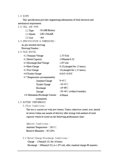
1.0SCOPEThis specification provides engineering information of both electrical and mechanical requirement.2.0CELL AND TYPE2.1 Type :Ni-MH Battery2.2 Model :LH-150AAH2.3 Size :AA3.0SPECIFICATION & DIMENSIONS:As per attached drawing.Drawing Number:4.0PACK RATING4.1 Nominal V oltage 1.2V/Cell4.2 Rated Capacity 1500mAh/0.2C4.3 Discharge End V oltage 1.0V/cell4.4 Rate Charge 0.1C(charged for 15 hours)4.5 Fast Charge 1C(charged for 1.25 hours)4.6 Trickle Charge 0.01C~0.05C4.7 Temperature (recommended)Standard Charge 0~45℃Trickle Charge -10~45℃Discharge -10~60℃Storage -20~40℃(within 6 months)4.8 Maximum Discharge Current:4500mA(continued)5.0BATTERY PERFORMANCE5.1Test Conditions:The test is carried out with new battery. Unless otherwise stated, tests shouldbe down within one month of delivery after testing with method of ratedcapacity which be listed on the following performance chart.Ambient Conditions:Ambient Temperature:20±5℃Relative Humidity:65±20%5.2Rated Charge/Discharge Conditions:Charge:150mA(0.1C) for 16 hoursDischarge:300mA(0.2C) to 1.0V/cell, after standard charge 60 minutes.6.0COSMETICBatteries should be without any cracking、rupture、dirt、shading、leakage and deformation.7.0STANDARD OF QUALITY ASSURANCE (AQL)All test ahould be done according the following method.(ref. MIL-STD-105E)Including:Capacity、Performance、Voltage、Internal Resistance8.0ASSURANCE PERIOD:One year of guarantee is valid for the defects caused by processing and materials.9.0NOTE:9.1Don‟t dispose of cell into fire or dismantled under any condition.9.2Don‟t mix different cells and capacity in same battery assembly.9.3Charge and discharge under specified ambient temperature recommend to ourspecification.9.4Short circuit leading to cell venting must be avoided.9.5Never solder onto cell directly.9.6Cell reversal should be avoided.9.7Use battery in extreme condition may affect the service life, such as extremetemperature、deep cycle、extreme over charge and over discharge.9.8Battery should be stored in a cool & dry place, please discharge before massstorage or transportation.9.9Once problems be found, stop using and send battery to local agent.REMARK:1.Cycle life:IEC61436Repeat 1 to 50 cycles, until the discharge time of the 50 cycle is less than 3 hours.10. CELL SPECIFICATION:。
NEC Energy Solutions ALM 12V35 高性能、长寿命、安全的铅离子电池说明书

HIGH PERFORMANCE, LONG LASTING, SAFE BATTERIES FOR TOUGH, CRITICAL APPLICATIONSNEC Energy Solutions ALM ™ family of lithium-ion batteries offers exceptional performance and long operating life.The ALM 12V35 delivers significant advantages over lead-acid batteries:High energy capacity even under high discharge rateand deep cyclingIndustry-leading service life in both cycling andfloat applicationsIntegrated, redundant safety protection circuitsAvailable Energy (at 1hr rate)Up to 60% greater Cycle Life (to 50% DOD)10–50X longer Calendar/Float Life Up to 5X longer Charging Time 10–100X faster Weight (Kg)50% lighterLong LifeExceptional 100% deep discharge cycle life Superior float, calendar, and shelf lifeExcellent partial state-of-charge enduranceHigh PerformanceHigh rate power delivery with consistent energy capacityFast, simple charging. Compatible with most lead acidchargersIntegrated intelligence and communications (ALM i-Series)Scalable arrays up to 48V, 350Ah (4S10P) without externalBattery Monitoring System (BMS)Robust SafetyEverSafe™ battery technology. Protection at the cell, battery,and system levelFast response short circuit protectionSafe, proven, high-performance Nanophosphate ® LiFePO4chemistrySealed ABS plastic case (UL 94-5VA flame retardant)Environmentally friendly; cells contain no lead or cadmiumTough, Critical ApplicationsStrong performance and long life across temperatureextremesLight weight with superior energy densitySimple, scalable system configurability up to 18kWh of energyUPS SYSTEMSTELECOM BACKUP POWERPV SOLAR-STORAGEOFF-GRID POWER ELECTRIC MOBILITYMEDICAL EQUIPMENT1001,00010,000100,0001,000,00010,000,00020406080100# o f C y c l e s t o 70% B O L C a p a c i t yDelta SOC (%)Cycle Life vs. Delta SOCBehavior of Lithium Nanophosphate® cellNumber of cycles is dependent upon average SOC, charge/discharge rates, temperature and calendar time.Actual results will depend on specific use cases. Contact NEC Energy Solutions for more details.The ALM12V35 is available in standard (s), intelligent (i), and High Power (HP) series to match application requirements. The i-Series offer integrated CAN or SMbus communications for access to critical battery status, usage tracking, State of Charge (SOC), run time to empty, and other parameters.Nominal Voltage13.2 V Nominal Capacity135 Ah Available Energy (BOL)462 WhMax. Charge/Discharge Current Pulse(1 sec)250 AMax. Inrush CurrentCharge or Discharge (0.3s)500 AMax. Continuous Discharge Current (to 100% Depth of Discharge)105 A4 210A4Max. Continuous Charge Current105 A4 210A4 Max. Recommended Charge Voltage14.4 VMax. Charger Voltage (w/o damage)60 V Recommended Float Voltage13.6 - 14.4 VCharge time @ max rate 20 min.@ 3C10 min.@ 6CMin. Float Voltage13.6 V Under-voltage Limit (min)8 V Operating Temperature5-40 to +60°C Recommended Storage Temperature2-40 to +35°C Transportation3-40 to +80°C1. Minimum Capacity – 33.6 Ah at beginning of life (BOL)2. Storage at higher temperature reduces the battery’s life3. Transportation up to two weeks4. Duration of maximum constant current is thermally limited by internalelectronics and depends on ambient temperature.5. Charge and discharge power, and energy availability, will be limited at the lowand high ends of the specified operating temperature range.SAFETY AND COMPLIANCEIEC62133; UL 1973REACH, RoHS and Battery Directive (2006/66/EC)Meets FCC 47CFR 15 Class B, IEC61000-6-1,-2, -3, -4, ICES-003 UN Manual of Tests and Criteria Part III1011121314110100TerminalVoltage(V)Discharge Time (Minutes)Typical 400W Constant PowerDischarge Behavior45°C25°C0°C-20°C1011121314110100 TerminalVoltage(V)Discharge Time (Minutes)Typical Constant Current DischargeBehavior at 25°C0.5C1C2C3C6C1011121314110100TerminalVoltageDischarge Time (Minutes)Typical Constant Power DischargeBehavior at 25°C200W400W825W1250WEnd Voltage30 min45 min60 min90 min120 min180 min240 min 10V886598456305231156118End Voltage20 min30 min45 min60 min90 min120 min240 min 10V10569463523189TELECOMMUNICATIONS POWER SYSTEMS Communications gear, whether in public or private networks, must meet critical up-time requirements, despite being deployed in harsh and difficult to access locations. The ALM 12V35 dramatically exceed the performance and life expectations of traditional back-up power solutions, whether in stable, weak,or off-grid environments. ALM 12V35 is ideal for:Base stations, Small cells, outside plant OSP equipment,Distributed Antenna Systems (DAS)Private wireless, Microwave systems, Central office power back-upOFF-GRID OR WEAK-GRID POWER SYSTEMS Off-grid power systems demand fast and frequent charge and discharge cycles, often in harsh environments with portability requirements. The ALM 12V35’s long cycle life, fast charging, and light weight are ideal for these challenging applications:Oil / gas / mining, remote sensors, electronic road signs, lightingUPS SYSTEMSUninterruptible Power Supplies are ubiquitous not only in data centers and small offices, but also in a broad array of industrial applications – anywhere where computers are used in critical applications. The exceptional power delivery capabilities, long life, and light weight ALM 12V35 enable UPS systems including:Industrial Automation, Data Center, Server UPSINTEGRATED PV SOLAR-STORAGE SYSTEMS Advanced battery systems promise to extend the utility ofthe solar PV systems experiencing rapid global adoption.In residential and small commercial environments with unreliable electric grids, high performance batteries are critical components. The fast charging and long life ability of ALM 12V35 – even in frequent partial state-of-charge scenarios – are key to effective PV+storage applications including:Remote sites, Residential PV with weak-grid systems, Small Commercial back-upMEDICAL EQUIPMENTMedical equipment increasingly relies on advanced batteries for operational portability. However, sidelining equipment for hoursto accommodate battery charging or frequent servicing directly impacts the cost and quality of patient care. The fast recharging and long operating life of the ALM 12V35 maximizes the value for:Mobile Carts, Diagnostic EquipmentELECTRIC MOBILITYMobility assistance systems for disabled persons energy storage that delivers consistent high power when needed,light weight and fast recharging. NEC Energy ALM batteries significantly outperform lead-acid batteries in these applications, including:Wheelchairs, Disability Scooters70%75%80%85%90%95%100%0 2.557.51012.51517.520Projected Cycle and Calendar Life ScenariosNEC Energy Solutions, Inc.155 Flanders RoadWestborough, MA 01581(508) 497-7319 Performance may vary depending on use conditions and application. NEC Energy Solutions, Inc. makes n o warranty explicit or implied with this data sheet. Contents subject to change without notice.ALM 12V35 (i-SERIES) INTELLIGENT BATTERIESThe intelligent ALM 12V35i batteries allow unprecedented monitoring and control of battery systems, eliminating the need for external sensors and monitoring systems. Each ALM 12V35i maintains detailed information on battery and cell-level operation, including:Battery voltage and current Relative State of Charge (SOC) Cell voltage and temperaturesFull charge and remaining capacity Cycle countIn addition, each ALM 12V35i allows user programmablethresholds and alarms for capacity, remaining time, under and over-voltage warnings, and temperature warnings. Battery activity, including time at different temperatures, is logged and available to the user. NEC Energy offers a Windows-based graphical software application for demonstrating the ALM 12V35i’s capabilities.The ALM 12V35i’s management functions are accessible through CAN Bus or SMBus interfaces. The CAN Bus interface allows 40 or more batteries to be daisy-chained into one link, and may be connected to a wide variety of smart power system controllers used in telecommunications and other industrial power systems. The SMBus interface allows up to 8 daisy-chained batteries and is specifically designed for medical cart and UPS systems.PHYSICAL AND MECHANICAL SPECFICATIONSORDERING INFORMATIONPower System ControllerDevice ControllerCommunicationsGatewayor or CAN bus or SMBus。
镍氢AAA800规格书
容量1
最小 典型
尺寸
直径 高度
重量
充电
内阻 at 1000Hz.
标准 快速
环境温度 充电
标准
快速 放电 储存
1.2V
0.2C放电
1C 放电
750毫安时2 800毫安时
700毫安时 750毫安时
毫米
寸
10.5
0 -0.5
Байду номын сангаас
44.5
0 -1.0
克
0.413
0 -0.020
1.752
0 -0.039
盎司
12
0.42
55欧姆 (充满电后)
80毫安(0.1C) X16小 时
800毫安(1C) X 1.25小时 oC
0oC to 45oC 10oC to 40oC -10oC to 50oC -10oC to 40oC
单体电池尺寸
电压(V)
电压(V)
主要特性 标准充电特性
1.8
1.7 1.6 1.5 1.4
00.5
Φ3.2
注: 1. 以0.1C充电需15小时充满。 2.额定容量,0.2C, 20oC 3. 平均容量,仅供参考 4. 内阻和重量仅为参考。
电压(V)
放电特性
1.5 1.4 1.3 1.2 1.1 1.0 0.9 0.8
0
放电: 800毫安 1.25小时 温度:100C/68 0F
150
300
余姚市中盛电子科技有限公司
规格说明书
发 往: 型 号: 编 制: 审 核:
岚宝电 器
NI-NH AAA 800H
魏姣辉 张娜达
地 址:浙江省余姚市梁辉镇南庙村 电 话:0574-62578042 邮 箱:wangxk2009@
量能科技(EPT BATTERY)镍氢电池生产流程图

EPT 深圳市量能科技有限公司
文件名称:生产和服务过程的控制程序 NI-MH 电池单粒生产流程图
去离 子水
文件编号 版本号 页码
DPP-013 A1 2/4
球镍、亚钴
发泡镍 镍带
Байду номын сангаас
铜网 合金粉
钢壳 底垫
隔膜
KOH
LiOH
NaOH
密封圈
密封胶 盖帽
混粉
制片
排钢壳
裁隔膜
配电液
浸胶圈
制片
称重分档
焊小纸
称重分档 软化 点焊
整形 贴胶纸
卷绕
测电阻 滚槽
涂胶 注液
加上垫 加圈
点焊 压盖 封口 洗电池 化成 测电压 分容 入库 包装出货
来料 (工序)过程 可选工序 全检工序 重点工序 (工序)终止
编制:
审批:
M300电池规格书V1.3_zlj_20100209

M300电池规格书文件编号项目名称拟制审核日期版本历史及修订说明1 编写目的和适用范围本规格书适用于无距科技 M300 机型使用的电池模块。
2 技术规格要求注1:加有PTC保护片;注2:测试条件:充电:1C充电到4.2 V放电:0.5C放电到3.0V当放电容量降至初始容量的80%时,所完成的循环次数定义为该电池的循环寿命;或者当其中任何一次循环的放电时间小于1.6小时,寿命即为终止。
注3:标准充电后,在规定条件下(温度: 23°C ±5°C湿度: 65 ± 20%RH)贮存30天,再以0.2C放电至3.0V所放出的容量。
注4:标准充电后, 在环境温度20℃±5℃的条件下,将电池开路搁置30d(周),再以0.2CA电流5放电至3.0V.2.2 电池保护性能要求2.3 充电曲线要求A充电曲线2.3.1 0.2 C5A充电,当电流端电压达到充电限制电压时,改为在环境温度20℃±5℃的条件下,以0.2C5A,恒压充电,直到充电电流小于或等于0.01C5测试结果要求:电池在恒流充电过程中,电池充电电量应占电池实际容量≥85%.其余部分电量应在恒压充电过程中完成.2.3.2 1 CA充电曲线5A充电,当电流端电压达到充电限制电压时,改为恒在环境温度20℃±5℃的条件下,以1C5A.压充电,直到充电电流小于或等于0.01C5测试结果要求:电池在恒流充电过程中,电池充电电量应占电池标称容量≥60%.其余部分电量应在恒压中充电过程中完成.2.3.3 0.2 CA放电曲线分析测试5A电流放电至终止将电池按4.2.3规定充电后搁置0.5h~1h,在20℃±5℃的条件下以0.2C5电压3V。
测试结果要求在手机关机截止电压中放出电量曲线应≥电池标称容量中的90%,应.整体放电曲线具有平台性.2.4 重物冲击电池放置于冲击台上,将10KG重物自1M高度自由落下,冲击已固定在夹具中的电池(电池的面积最大的面应与台面).测试结果要求:电池允许变形,但应不起火,不爆炸.2.5 热冲击1)电池放置于热箱中,温度以(5℃±2℃)/min的速率升至130℃±2℃并保温30min.测试结果要求电池应不起火,不爆炸.2.6 过充电将电池拆除保护板后,将接有热电偶的电池置于通风橱中,连接正负极于一恒流恒压电源,调节电流至3C5A、电压为4.5V,然后对电池以3C5A充电,直到电池电压为4.5V,电流将到接近0A。
电池规格书(Ni-MH SC2500mAh)
NI-MH BATTERYDELIVERY SPECIFICATIONS镍氢电池规格书******************PRESENTED TO(呈送):MODEL NO.(产品型号): Ni-MH SC2500mAh 1.2VDATE(制作日期): 20th July 2012 Customer Part No.(客户物料编码) :Add:地址:Postcode(邮编): http(网址):Tel(电话): Fax(传真):E-mail(邮箱):1. Scope (适用范围)This specification governs the performance of the following Nickel-Metal Hydride cylindricalbattery 。
本规格书适用于下述型号的可充性圆柱形镍氢电池。
2. Innovation model(亿诺型号):Ni-MH SC2500mAh 1.2V。
3. External Appearance(外观)The cell / battery shall be free from cracks, scars, breakage, rust,discoloration, leakage and deformation. 电池/电池组外观无破裂、划痕、变形、生锈、污迹、电解液泄漏等不良现象。
4. Ratings(规定参数)The data involving the nominal voltage and the approximate weight of the battery pack。
5. Performance(电池性能)Unless otherwise stated, tests should be done within one month of delivery under the following conditions: 除非其它规定,测试应在到货之日起1个月内进行,并且符合以下测试条件:Relative humidity(相对湿度):65±20%。
- 1、下载文档前请自行甄别文档内容的完整性,平台不提供额外的编辑、内容补充、找答案等附加服务。
- 2、"仅部分预览"的文档,不可在线预览部分如存在完整性等问题,可反馈申请退款(可完整预览的文档不适用该条件!)。
- 3、如文档侵犯您的权益,请联系客服反馈,我们会尽快为您处理(人工客服工作时间:9:00-18:30)。
EPT BATTERY CO LTD Product specificationCustomer:Model:EPT AAJ1800mAh-LDate: 2010-5-12Type:- Rechargeable Nickel MetalHydrideModel:EPT AAJ1800mAh-LCell Size: AANominal voltage: 1.2VTypical Weight about 25g(ref)Capacity (20℃, discharge at 0.2Cto ccv=1.0V)Typical: 1830mAh(ref)Minimum: 1800mAhCharge condition(20℃)Charging Condition: charge at 180mA for16h Fast Charge: 900mA~1800mADT/dt=0.8℃/min(0.5C~0.9℃0.8C~1℃/min(1C) /TCO:(45~55) ℃ /time: charge capacity reach to 105% nominal capacity) Trickle charge: 0.05 I t A ~0.1 I t AMax over-charge current 0.1 I t A charge for 48 hrsDischarge conditionDischarge cut off voltage: 1.0VMaximum Discharge Current 1800mAStorage Temperature(65±20%RH)Storage(1year)-20℃~25℃Storage(six month)-20℃~35℃Storage(1 month)-20℃~45℃Storage(7days)-20℃~55℃Operation temperature(Relative humidity:65±20%RH)Discharge: -20℃~60℃Charge:0℃~45℃Fast charge 10℃~40℃Trickle charge 0℃~45℃1、PERFORMANCEUnless otherwise stated, tests should be done within one month of delivery under the following conditions Ambient Temperature Ta:20±5℃Relative Humidity:65±20%RHNotes: Standard Charge/Discharge Condition:Charge:180mA(0.1 IA)×16 hrs Discharge: 360mA (0.2 I A) to 1.0V/CellNotes:1. RT: Ambient Temperature.2. Approximate charge time from discharged rate, for reference only. 1.1.2 IEC 61951-2(2003)IEC61951-2(2003) Cycle Life Test:3. EXTERNAL APPEARANCEThe cell / battery shall be free from cracks, scars, breakage, rust, discoloration, leakage and deformation4. WARRANTYOne year limited warranty against workmanship and material defects.5. WARRANTY5.1 Do not reverse charge batteries5.2 Do not short circuit batteries, permanent damage to batteries may result5.3 Do not subject batteries to adverse condition such as extreme temperature, deep cyclingand excessive5.4 Store batteries in a cool dry place, Always disharge batteries before bulk storage orshipment.5.5Do not solder directly to cells or batteries.5.6 If find any noise, excessive temperature or leakage from a battery, please stop its use.5.7 Do not incinerate or mutilates batteries, may burst or release toxic material.5.8 Do not mix new batteries in use with semi-used batteries, over-discharge may occur. 5.9 Do not remove the outer sleeve from a battery pack nor cut into its housing.5.10 Never put a battery into water or seawater6. CAUTION6.1 Batteries should be charged prior to use6.2 For charging methods please referred to our technical handbookUse the correct charger for Ni-MH batteries6.3 Avoid batteries being used in an airtight compartment. Ventilation should be providedinside the battery compartment ,otherwise batteries may generate hydrogen gas , which could cause an explosion if exposed to an ignition source6.4 Do not attempt to take batteries apart or subject them to pressure or impact. Heat may begenerated or fire may result. The alkaline electrolyte is harmful to eyes and skin, and it may damage clothing upon contact6.5 Keep away from children. If swallowed, contact a physician at once.6.6 When using a new battery for the first time or after long term storage, please fully charge thebattery before use6.7 When using a new battery in use with semi-used batteries, over-discharge may occur. 6.8When connecting a battery pack to a charger, ensure correct polarity.6.9 When the battery is hot, please do not touch it and handle it, until it has cooled down.6.10 When find battery power down during use, please switch off the device to avoid overdischarge.6.11 Unplug a battery by holding the connector itself and not by pulling at its cord.6.12 After use, If the battery is hot. Before recharging it, allow it to cool in a well-ventilated placeout of direct sunlight.7、storage7.1 In order to ensure the battery to maintain the capacity level, We suggest Ni-MH battery andbattery pack should be stored under the condition of the -20 ~ 35 ℃, low humidity, nocorrosive gases 。
7.2 Ni-MH battery to avoid the high temperature or high humidity storage, otherwise it wouldlead to the battery leakage, rust, and the lower capacity7.3 The long-term storage may lead to NIMH batteries and battery packs to reduce the capacityand need 1-3 charge / discharge cycles to reach the maximum discharge capacity.7.4 Three months after placing the battery need to be charge/discharge for one cycles。
Type :Rechargeable Nickel Metal Hydride Cylindrical Cell Nominal Dimension :Φ=14.5mm(with sleeve) H=50.5mm Applications: Recommended discharge current180mA to 1800mA Nominal Voltage: 1.2VCapacity:Minimum: 1800mAh Typical: 1830mAhWhen discharged at 0.2C to 1.0V at 20℃ Charging Condition: 180mA for 16 hrs at 20℃ Fast Charge: 900mA to 1800mA (0.5to1C) Charge termination control recommended control parameters: △V: 0~5mvDT/dtˉ: 0.8℃/min(0.5 to 0.9 C)70.8~1℃/min(1C)TCOˉ: 45~50℃Timeˉ: 105% nominal inputFor reference only Service life: >500 cycles (IEC standard) Continuous: 180mA maximum current for 48 hrs Overcharge No conspicuous deformation And/or leakage Weight: about 25g Internal Resistance: Max 35mΩ upon fully charged at1000HZMax. Charging Voltage :1.5V at 180mA charging Ambient Temperature :Standard charging:0 to 45℃Fast charging :10 to 45℃Discharging :-20 to 50℃Storage : -20 to 35℃1 C0.5CFast charge (charge control required) Voltage (V)Charge 0.1C *16hrs at20℃0.5C 0.2C 0.1CLow rate discharge Voltage (V)Discharge time (hrs)50.5 (+0/-1.5)4.8(ref)14.5(+0/-0.7)。