恒温焊台操作指导书
恒温控制器操作指南说明书
Step 11. Enter to the Thermocouple Type Input Submenu Press d to display flashing, previously selected Thermocouple type.Step 12. Scroll through available selection of TC types Press b to sequence thru flashing Thermocouple types,(select k -for type "K" CHROMEGA TM /ALOMEGA TM )J K T E N DIN J R S B C - TC types J k t E N dN J R S b C - DisplayStep 13. Store TC typeAfter you have selected the Thermocouple type press d to store your selection, the instrument automatically advances to the next menu item.Step 14. Enter to Reading Configuration MenuThe display shows RDG Reading Configuration, which is the top menu for 4 submenus: Decimal Point, Degree Units, Filter Constant and Input/Reading Submenus.Step 15. Enter to Decimal Point Submenu Press dto show DEC Decimal Point.Step 16. Display the Decimal Point positionPress d again to display the flashing Decimal Point position.Step 17. Select the Decimal Point position Press b to select FFF.F Decimal Point position.Step 18. Store selected Decimal Point positionBy pressing d momentarily the Decimal Point position will be stored and the instrument will go to the next menu item.Step 19. Enter to Temperature Unit Submenu Display shows TEMP Temperature Unit.Step 20. Display available Temperature Units Press d to display the flashing Degree °F or °C .Step 21. Scroll through Temperature Units selection Press b to select °F Degree.Step 22. Store the Temperature UnitPress d to display momentarily that the Degree Unit has been stored and the instrument will go automatically to the next menu item.Step 23. Enter the Filter Constant Submenu Display shows FLTR Filter Constant Submenu.Step 24. Display the Filter Constant Value Submenu Press d to display the flashing, previously selected Filter Constant.Step 25. Scroll through available Filter Constants Press b to sequence thru Filter Constants 0001, 0002,0004, 0008, 0016, 0032, 0064and 0128.Step 26. Store the Filter ConstantPress d momentarily to store 0004Filter Constant and the instrument will automatically go to the next menu item.Step 27. Enter Alarm 1 MenuPress a until the ALR1Alarm 1 Menu appears on the Display. In the following steps we are going to DisableLatch, Active Above, Deadband 020.0, and above Setpoint 1Value will activate Alarm 1.Step 28. Select Latch Type SubmenuPress d to display flashing DSBL / ENBL .If flashing DSBL is displayed, press a , if ENBL is displayed, press b until DSBL is displayed, then press d to store and go to the next menu item.Step 29. Select the Above Type of Active Submenu Press d . If flashing ABoV Above is displayed, press a ,otherwise press b until ABoV is displayed. Press d to store and advance to next menu item.WARRANTY/DISCLAIMEROMEGA ENGINEERING, INC. warrants this unit to be free of defects in materials and workmanship for a period of 61 months from date of purchase. OMEGA’s WARRANTY adds an additional one (1) month grace period to the normal five (5) year product warranty to cover handling and shipping time. T his ensures that OMEGA’s customers receive maximum coverage on each product.If the unit malfunctions, it must be returned to the factory for evalua-tion. OMEGA’s Customer Service Department will issue an Authorized Return (AR) number immediately upon phone or written request. Upon examination by OMEGA, if the unit is found to be defective, it will be repaired or replaced at no charge. OMEGA’s WARRANTY does not apply to defects resulting from any action of the purchaser, includ-ing but not limited to mishandling, improper interfacing, operation outside of design limits, improper repair, or unauthorized modifica-tion. This WARRANTY is VOID if the unit shows evidence of having been tampered with or shows evidence of having been damaged as a result of excessive corrosion; or current, heat, moisture or vibration; improper specification; misapplication; misuse or other operating conditions outside of OMEGA’s control. Components in which wear is not warranted, include but are not limited to contact points, fuses, and triacs.OMEGA is pleased to offer suggestions on the use of its vari-ous products. However, OMEGA neither assumes responsibil-ity for any omissions or errors nor assumes liability for any damages that result from the use if its products in accordance with information provided by OMEGA, either verbal or writ-ten. OMEGA warrants only that the parts manufactured by the company will be as specified and free of defects. OMEGA MAKES NO OTHER WARRANTIES OR REPRESENTATIONS OF ANY KIND WHATSOEVER, EXPRESSED OR IMPLIED, EXCEPT THAT OF TITLE, AND ALL IMPLIED WARRANTIES INCLUDING ANY W ARRANTY OF MERCHANTABILITY AND FITNESS FOR A PARTICULAR PURPOSE ARE HEREBY DISCLAIMED. LIMITATION OF LIABILITY: The remedies of purchaser set forth herein are exclusive, and the total liability of OMEGA with respect to this order, whether based on contract, warran-ty, negligence, indemnification, strict liability or otherwise, shall not exceed the purchase price of the component upon which liability is based. In no event shall OMEGA be liable for consequential, incidental or special damages.CONDITIONS: Equipment sold by OMEGA is not intended to be used, nor shall it be used: (1) as a “Basic Component” under 10 CFR 21 (NRC), used in or with any nuclear installation or activity; or (2) in medical appli-cations or used on humans. Should any Product(s) be used in or with any nuclear installation or activity, medical application, used on humans, or misused in any way, OMEGA assumes no responsibility as set forth in our basic WARRANT Y/DISCLAIMER language, and, additionally, purchaser will indemnify OMEGA and hold OMEGA harmless from any liability or damage whatsoever arising out of the use of the Product(s) in such a manner.RETURN REQUESTS/INQUIRIESDirect all warranty and repair requests/inquiries to the OMEGA Customer Service Department. BEFORE RE URNING ANY PRODUC (S) O OMEGA, PURCHASER MUS OB AIN AN AUTHORIZED RETURN (AR) NUMBER FROM OMEGA’S CUSTOMER SERVICE DEPART MENT (IN ORDER T O AVOID PROCESSING DELAYS). T he assigned AR number should then be marked on the outside of the return package and on any correspondence.FOR WARRANTY RETURNS, please have the followinginformation available BEFORE contacting OMEGA:1. Purchase Order number under which the product was PURCHASED,2.3. Model and serial number of the product under warranty, and Repair instructions and/or specific problems relative to the product.FOR NON-WARRANTY REPAIRS, consult OMEGA for current repair charges. Have the following information available BEFORE contacting OMEGA:1. P urchase Order number to cover the COST of the repair or calibration,2.3.Model and serial number of the product, and R epair instructions and/or specific problems relative to the product.OMEGA’s policy is to make running changes, not model changes, whenever an improvement is possible. This affords our customers the latest in technology and engineering.OMEGA is a trademark of OMEGA ENGINEERING, INC.© Copyright 2018 OMEGA ENGINEERING, INC. All rights reserved. T his document may not be copied, photocopied, reproduced, translated, or reduced to any electronic medium or machine-readable form, in whole or in part, without the prior written consent of OMEGA ENGINEERING, INC.MQS 3720/0818This Quick Start Reference provides information onsetting up your instrument for basic operation. Thelatest complete Communication and OperationalManual as well as free Software and ActiveXControls are available at or onthe CD-ROM enclosed with your shipment.The instrument is a panel mount device protected in accordance with EN 61010-1:2001, electrical safety requirements for electrical equipment for measurement, control and laboratory.Remember that the unit has no power-on switch. Building installation should include a switch or circuit-breaker that must be compliant to IEC 947-1 and 947-3. SAFETY:•Do not exceed voltage rating on the label located onthe back of the instrument housing.•Always disconnect power before changing signal andpower connections.•Do not use this instrument on a work bench withoutits case for safety reasons.•Do not operate this instrument in flammable orexplosive atmospheres.EMC:•Whenever EMC is an issue, always use shielded cables.•Never run signal and power wires in the same conduit.•Use signal wire connections with twisted-pair cables.•Install Ferrite Bead(s) on signal wire close to theinstrument if EMC problems persist.。
恒温电烙铁使用作业指导书
恒温电烙铁使用作业指导书
一.目的:
维护恒温电烙铁的正常使用,提供正确的方法予以指导。
二.使用者:
修理员及工程部人员
三.使用方法:
1.使用电源插头插至220V插头上,接通电源,将烙铁头放至电烙铁架上。
2.将I/O开关打开,电烙铁加热,将烙铁温度调节至相应温度。
有铅为325℃+/-25℃,无铅为370℃+/-10℃。
3.当加热指示灯HEATER亮且闪烁时,表示烙铁头温度已达到设定值左右,此时可以进行焊接动作或加锡。
4.在进行烙铁焊接时,烙铁头在焊盘上不可停留时间过长,以2-3秒为宜,以免烧坏物料与焊盘。
四:要求及注意事项
1.烙铁头在使用中须放置于烙铁架上,不可放置于其它地方。
2.烙铁使用完后,须在烙铁头上加少许焊锡,以防烙铁头氧化。
3.使用烙铁时要小心高温,以免烫伤人或其它不耐高温物品。
4.烙铁温度调节纽未经许可,其他人不可随意调节。
5.如电烙铁头不良,维修员须向领班申领、更换。
如电烙铁不能加热,交于工程部技术人员处理。
6.使用完毕,须将电烙铁电源关闭。
恒温仪器操作指南说明书
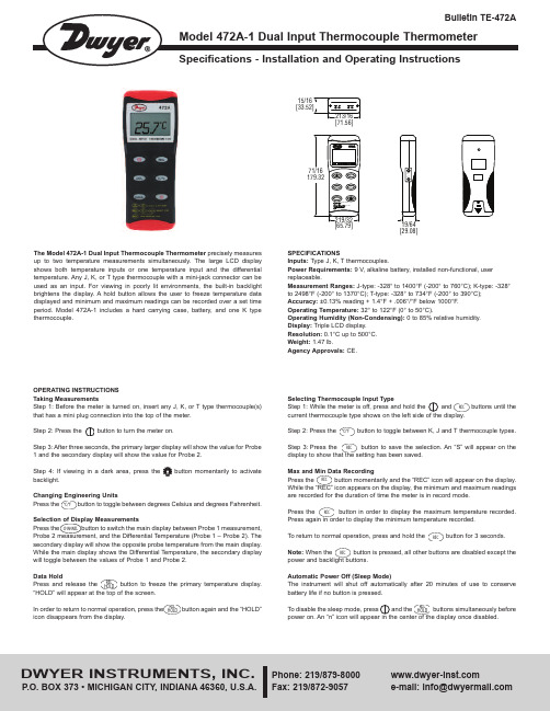
OPERATING INSTRUCTIONSTaking MeasurementsStep 1: Before the meter is turned on, insert any J, K, or T type thermocouple(s)that has a mini plug connection into the top of the meter.Step 2: Press the button to turn the meter on.Step 3: After three seconds, the primary larger display will show the value for Probe1 and the secondary display will show the value for Probe 2.Step 4: If viewing in a dark area, press the button momentarily to activatebacklight.Changing Engineering UnitsPress the button to toggle between degrees Celsius and degrees Fahrenheit.Selection of Display MeasurementsPress the button to switch the main display between Probe 1 measurement,Probe 2 measurement, and the Differential Temperature (Probe 1 – Probe 2). Thesecondary display will show the opposite probe temperature from the main display.While the main display shows the Differential Temperature, the secondary displaywill toggle between the values of Probe 1 and Probe 2.Data HoldPress and release the button to freeze the primary temperature display.“HOLD” will appear at the top of the screen.In order to return to normal operation, press the button again and the “HOLD”icon disappears from the display.The Model 472A-1 Dual Input Thermocouple Thermometer precisely measuresup to two temperature measurements simultaneously. The large LCD displayshows both temperature inputs or one temperature input and the differentialtemperature. Any J, K, or T type thermocouple with a mini-jack connector can beused as an input. For viewing in poorly lit environments, the built-in backlightbrightens the display. A hold button allows the user to freeze temperature datadisplayed and minimum and maximum readings can be recorded over a set timeperiod. Model 472A-1 includes a hard carrying case, battery, and one K typethermocouple.SPECIFICATIONSInputs: Type J, K, T thermocouples.Power Requirements: 9 V, alkaline battery, installed non-functional, userreplaceable.Measurement Ranges: J-type: -328° to 1400°F (-200° to 760°C); K-type: -328°to 2498°F (-200° to 1370°C); T-type: -328° to 734°F (-200° to 390°C);Accuracy: ±0.13%reading + 1.4°F + .006°/°F below 1000°F.Operating Temperature: 32° to 122°F (0° to 50°C).Operating Humidity (Non-Condensing): 0 to 85% relative humidity.Display:Triple LCD display.Resolution:0.1°C up to 500°C.Weight:1.47 lb.Agency Approvals: CE.[29.08][65.79]15/16RELHOLDRELHOLD°C/°FCHANNELDWYER INSTRUMENTS, INC.Phone: 219/Fax: 219/872-9057e-mail:******************©Copyright 2015 Dwyer Instruments, Inc.Printed in U.S.A. 5/15FR# 443743-00 Rev. 4BATTERY REPLACEMENTThe Dual Input Thermocouple Thermometer displays “BAT” as a visual low battery indication.To Replace the Battery:1. Make sure the unit is powered off.2. Remove thermocouples from the top of the instrument.3. Lay face down on a clean, flat surface.4. Open battery compartment by pushing in tab and lifting cover.5. Replace battery, taking note of the indicated polarity.6. Replace the cover.MAINTENANCEA periodic check of the system calibration is recommended. Model 472A-1 is not field serviceable and should be returned if repair is needed (field repair should not be attempted and may void warranty). Be sure to include a brief description of the problem plus any relevant application notes. Contact customer service to receive a return goods authorization number before shipping.If the thermometer fails to power on, it is likely that the batteries also need to be replaced.Failing to turn the thermometer off may result in malfunction of the unit. Dispose of used battery promptly and keep away fromchildren.。
恒温烙铁作业指导书
恒温烙铁作业指导书
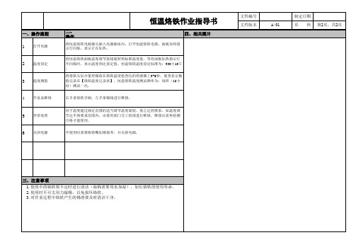
二、 操作
四、相关图片
将恒温烙铁电源插头插入电源插座内,打开恒温烙铁电源,面板加热指 示灯闪烁,表示正在加热。
将恒温烙铁面板温度调节按钮旋转到标准温度值,等待面板加热指示灯 不闪烁时,表示温度到达设定值。恒温烙铁温度设定标准为:330±10℃ 。
不使用时需将铬铁嘴加锡保养,并关掉电源.
文件编号 文件版本
A/01
制定日期 页 码 第2页,共2页
三、注意事项
1.使用中的铬铁要不定时进行清洁(海棉需要用水加湿),加长烙铁的使用寿命, 2.使用时不可太用力敲锡,以免损坏铬铁。 3.对作业过程中烙铁产生的锡渣要及时清洁净。
将烙铁头加少量焊锡放在烙铁温度检查仪的传感器上3-5秒。观查显示数 值记录在【烙铁温度记录表】。恒温烙铁温度测试频率为:每班(12小 时)测试一次.
右手拿烙铁手柄,左手拿锡线进行维修。
对于温度超过规定范围的适当调节温度旋钮,使之达到要求,如温度调 节达不到要求范围内,由使用部门交工程部进行维修,维修后需再检测 合格才能使用.
Bakon BK936 恒温焊台 使用说明

BK936 恒温焊台
使用说明
本说明书中,指出预防事故发生的重要事项和产品的使用方法, 请仔细阅读本说明书,安全使用本产品。阅读后,请将此说明书 妥善保管。
目录
包装 清单…… …………… …… … …… …………… …… … …… … ……1 组装 ……… … ………………… ……… ………… ……………… … ……1 规格 … ……… …………… …… … …… ……… …………… ……… ……2 性能 特 点… ……………… …… ……… …………… …… … …… … ……2 设定 温度…… ………………… … …… ………… ………………… ……2 校准 烙铁温度 ………………… … …… ……… …………… …… … ……3 烙铁 头的维 护 与使用…… …… ……… ……… ………… … …… … ……3 烙铁 头 的保养 ……… …… …… … …… ………… ………………… ……4 排除 故 障指 南……… ………… ……… ……… …………… …… … ……4 部件 清单…… …………… …… … …… ……… ………… ……… … ……5 发热 元件的检 查………… …… … …… ………… ………………… ……6
部件名称 变压器
下盖 线卡 脚垫 电源线 保险丝 电 源P C B板 电源开关
-5-
发热元件的检查
拔出手柄插头,测试连接插 头的脚与脚之间的电阻值如下:
如果“a”与“c”的电阻值有异 于上表电阻值,需更换发热元件(传 感器)或电线,请参照如下程序进行。
如果“b”电阻值大于上表电阻值, 则要用砂纸或钢绒轻轻擦除如图所示部 位的氧化层。
注意事项
警告 本使用说明之:“警告”和“注意”的定义如下: 警告 滥用可能导致使用者重伤或死亡。 注意 滥用可能导致使用者受伤或对涉及物体造成实质破坏。为您本
恒温控制器用户操作指南说明书
Step 11. Enter to the Thermocouple Type Input Submenu Press d to display flashing, previously selected Thermocouple type.Step 12. Scroll through available selection of TC types Press b to sequence thru flashing Thermocouple types,(select k -for type "K" CHROMEGA ®/ALOMEGA ®)J K T E N DIN J R S B C - TC types J k t E N dN J R S b C - DisplayStep 13. Store TC typeAfter you have selected the Thermocouple type press d to store your selection, the instrument automatically advances to the next menu item.Step 14. Enter to Reading Configuration MenuThe display shows RDG Reading Configuration, which is the top menu for 4 submenus: Decimal Point, Degree Units,Filter Constant and Input/Reading Submenus.Step 15. Enter to Decimal Point Submenu Press d to show DEC Decimal Point.Step 16. Display the Decimal Point positionPress d again to display the flashing Decimal Point position.Step 17. Select the Decimal Point position Press b to select FFF.F Decimal Point position.Step 18. Store selected Decimal Point positionBy pressing d momentarily the Decimal Point position will be stored and the instrument will go to the next menu item.Step 19. Enter to Temperature Unit Submenu Display shows TEMP Temperature Unit.Step 20. Display available Temperature Units Press d to display the flashing Degree °F or °C .Step 21. Scroll through Temperature Units selection Press b to select °F Degree.Step 22. Store the Temperature UnitPress d to display momentarily that the Degree Unit has been stored and the instrument will go automatically to the next menu item.Step 23. Enter the Filter Constant Submenu Display shows FLTR Filter Constant Submenu.Step 24. Display the Filter Constant Value Submenu Press d to display the flashing, previously selected Filter Constant.Step 25. Scroll through available Filter Constants Press b to sequence thru Filter Constants 0001, 0002,0004, 0008, 0016, 0032, 0064and 0128.Step 26. Store the Filter ConstantPress d momentarily to store 0004Filter Constant and the instrument will automatically go to the next menu item.Step 27. Enter Alarm 1 MenuPress a until the ALR1Alarm 1 Menu appears on the Display. In the following steps we are going to DisableLatch, Active Above, Deadband 020.0, and above Setpoint 1Value will activate Alarm 1.Step 28. Select Latch Type SubmenuPress d to display flashing DSBL / ENBL .If flashing DSBL is displayed, press a , if ENBL is displayed, press buntil DSBL is displayed, then press d to store and go to the next menu item.Step 29. Select the Above Type of Active Submenu Press d . If flashing ABoV Above is displayed, press a ,otherwise press b until ABoV is displayed. Press d to store and advance to next menu item.MQS3716-SM/0305iLD24 Big Display Universal Temperature&ProcessSimplified Menu (-SM)WARRANTY/DISCLAIMEROMEGA ENGINEERING, INC. warrants this unit to be free of defects in materials and workmanship for a period of 61 months from date of purchase. OMEGA’s WARRANTY adds an additional one (1) month grace period to the normal five (5) year product warranty to cover handling and shipping time. T his ensures that OMEGA’s customers receive maximum coverage on each product.If the unit malfunctions, it must be returned to the factory for evalua-tion. OMEGA’s Customer Service Department will issue an Authorized Return (AR) number immediately upon phone or written request. Upon examination by OMEGA, if the unit is found to be defective, it will be repaired or replaced at no charge. OMEGA’s WARRANTY does not apply to defects resulting from any action of the purchaser, includ-ing but not limited to mishandling, improper interfacing, operation outside of design limits, improper repair, or unauthorized modifica-tion. This WARRANTY is VOID if the unit shows evidence of having been tampered with or shows evidence of having been damaged as a result of excessive corrosion; or current, heat, moisture or vibration; improper specification; misapplication; misuse or other operating conditions outside of OMEGA’s control. Components in which wear is not warranted, include but are not limited to contact points, fuses, and triacs.OMEGA is pleased to offer suggestions on the use of its vari-ous products. However, OMEGA neither assumes responsibil-ity for any omissions or errors nor assumes liability for any damages that result from the use if its products in accordance with information provided by OMEGA, either verbal or writ-ten. OMEGA warrants only that the parts manufactured by the company will be as specified and free of defects. OMEGA MAKES NO OTHER WARRANTIES OR REPRESENTATIONS OF ANY KIND WHATSOEVER, EXPRESSED OR IMPLIED, EXCEPT THAT OF TITLE, AND ALL IMPLIED WARRANTIES INCLUDING ANY W ARRANTY OF MERCHANTABILITY AND FITNESS FOR A PARTICULAR PURPOSE ARE HEREBY DISCLAIMED. LIMITATION OF LIABILITY: The remedies of purchaser set forth herein are exclusive, and the total liability of OMEGA with respect to this order, whether based on contract, warran-ty, negligence, indemnification, strict liability or otherwise, shall not exceed the purchase price of the component upon which liability is based. In no event shall OMEGA be liable for consequential, incidental or special damages.CONDITIONS: Equipment sold by OMEGA is not intended to be used, nor shall it be used: (1) as a “Basic Component” under 10 CFR 21 (NRC), used in or with any nuclear installation or activity; or (2) in medical appli-cations or used on humans. Should any Product(s) be used in or with any nuclear installation or activity, medical application, used on humans, or misused in any way, OMEGA assumes no responsibility as set forth in our basic WARRANT Y/DISCLAIMER language, and, additionally, purchaser will indemnify OMEGA and hold OMEGA harmless from any liability or damage whatsoever arising out of the use of the Product(s) in such a manner.RETURN REQUESTS/INQUIRIESDirect all warranty and repair requests/inquiries to the OMEGA Customer Service Department. BEFORE RE URNING ANY PRODUC (S) O OMEGA, PURCHASER MUS OB AIN AN AUTHORIZED RETURN (AR) NUMBER FROM OMEGA’S CUSTOMER SERVICE DEPART MENT (IN ORDER T O AVOID PROCESSING DELAYS). T he assigned AR number should then be marked on the outside of the return package and on any correspondence.FOR WARRANTY RETURNS, please have the followinginformation available BEFORE contacting OMEGA:1. Purchase Order number under which the product was PURCHASED,2.3. Model and serial number of the product under warranty, and Repair instructions and/or specific problems relative to the product.FOR NON-WARRANTY REPAIRS, consult OMEGA for current repair charges. Have the following information available BEFORE contacting OMEGA:1. P urchase Order number to cover the COST of the repair or calibration,2.3.Model and serial number of the product, and R epair instructions and/or specific problems relative to the product.OMEGA’s policy is to make running changes, not model changes, whenever an improvement is possible. This affords our customers the latest in technology and engineering.OMEGA is a trademark of OMEGA ENGINEERING, INC.© Copyright 2018 OMEGA ENGINEERING, INC. All rights reserved. T his document may not be copied, photocopied, reproduced, translated, or reduced to any electronic medium or machine-readable form, in whole or in part, without the prior written consent of OMEGA ENGINEERING, INC.***********************Servicing North America:Omega Engineering, Inc.Toll-Free: 1-800-826-6342 (USA & Canada only)Customer Service: 1-800-622-2378 (USA & Canada only) Engineering Service: 1-800-872-9436 (USA & Canada only) Tel: (203) 359-1660 Fax: (203) 359-7700 e-mail:**************For Other Locations Visit /worldwidehis Quick Start Reference provides information on setting up your instrument for basic operation. The latest complete Communication and Operational Manual as well as free Software and ActiveX Controls are available at or on the CD-ROM enclosed with your shipment .SAFETY CONSIDERATIONThe instrument is a panel mount device protected in accordance with EN 61010-1:2001, electrical safetyrequirements for electrical equipment for measurement, control and laboratory.Remember that the unit has no power-on switch. Building installation should include a switch or circuit-breaker that must be compliant to IEC 947-1 and 947-3.SAFETY:•Do not exceed voltage rating on the label located on the back of the instrument housing.•Always disconnect power before changing signal and power connections.•Do not use this instrument on a work bench without its case for safety reasons.•Do not operate this instrument in flammable or explosive atmospheres.EMC:•Whenever EMC is an issue, always use shielded cables. •Never run signal and power wires in the same conduit.•Use signal wire connections with twisted-pair cables.•Install Ferrite Bead(s) on signal wire close to the instrument if EMC problems persist.。
fx950焊台说明书

fx950焊台说明书FX950焊台是一种高性能的电子焊接工具,适用于各种电子零件的连接和修复。
本文将详细介绍FX950焊台的使用说明、注意事项以及常见问题解答等内容,以供用户参考。
一、产品概述FX950焊台是一种微处理器控制的先进电子焊接工具,具有快速加热和恒温控制的特点。
它采用陶瓷发热芯片作为加热元件,具有短时间内快速加热的优势,同时可通过控制电路精确控制焊接温度,确保焊接质量。
二、操作方法1. 连接电源:将FX950焊台的电源线插入电源插座,并接通电源开关。
焊台的数字显示屏会显示当前的温度值。
2. 设置温度:按下“设置”按钮,数字显示屏上会显示“SET”字样,此时可使用“+”和“-”按钮来设置所需的焊接温度。
设置完成后,再次按下“设置”按钮来确认设定。
3. 加热预热:在设定好的温度下,焊台将开始加热,当显示屏上的温度值达到设定温度时,焊台会自动转变为恒温模式,保持设定温度不变。
4. 开始焊接:将焊锡丝插入焊台的焊锡槽中,焊锡丝会自动融化,开始焊接。
焊接时,将焊锡丝接触到待焊接的电子零件上,等待瞬间就能焊接完成。
5. 安全停机:焊台具有定时安全功能,当焊接时间超过设定时间后,焊台会自动停机,以防止过热和意外发生。
三、注意事项1. 使用时应戴上防静电手套,并确保焊台工作区域干燥,避免电子元器件受潮。
2. 在使用前应检查焊锡槽内是否有残留的焊锡,如有,应先清理干净后再使用。
3. 注意焊接时的温度控制,避免温度过高或过低。
4. 使用时应尽量避免将焊锡丝长时间留在焊台上,以免造成焊锡丝过热。
5. 应定期检查焊台的工作状态,确保设备正常。
6. 当不使用焊台时,应断开电源并拔掉插头,以免发生意外。
四、常见问题解答1. 为什么焊台加热速度很慢?答:可能是由于供电电压不稳定或加热元件损坏导致的。
应检查供电电压是否稳定,并联系售后服务进行维修。
2. 能否更换焊台的加热元件?答:可以更换,但建议联系售后服务专业人员进行维修,以确保焊接质量和安全。
一、恒温电焊台使用要领
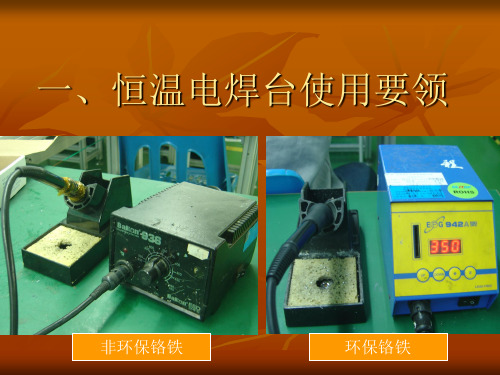
非环保铬铁
环保铬铁
1.1.使用前的准备
1.1.1接上220V电源,然后 再将电焊台电源开关打 开 (ON),指示灯亮。 1.1.2电焊台接地是否接地 良好. 1.1.3检测温度并调到 非 环保铬铁300+10℃,环保 铬铁调至370+10℃ 1.1.4给清洁海棉加水,以 保湿润. 1.1.5戴好防静电手腕带
三、操作安全
3.1切勿触及焊铁头附近的金属部分。 3.2切勿在易燃体附近使用烙铁。 3.3休息时或完工后应关掉烙铁。 3.4更换部件或更换焊铁头时,应关掉电源,并待焊 铁头冷却至室温。
1.2.3 使用完后应关掉控制 箱的电流开关置OFF位。
二、电焊台之保养与维护
2.1切勿使用焊铁头进行焊接以外的工作。 2.2切勿将焊铁敲击工作台或其它金属以清除焊剂残渣,此举 可能严重震损焊铁 2.3切勿擅自自动电焊台。 2.4勿弄湿电焊台,或手湿时也不也使用电焊台。 2.5烙铁在使用过程中,清洁海棉应保护湿润。
1.2.电焊台的操作使用
1.2.1烙铁的握持:
Hale Waihona Puke 烙铁在焊接时,一般烙铁与焊接面以45°左右斜度握持 焊接,主要是为了操作灵活方便,还要根据工艺的焊接 要求作相应的角度调整,以达更好的焊接效果。
1.2.2焊接要求:
标准 良品限度 不良品
锡点状态 焊点一般要求光滑、 饱满,不虚焊、假焊、 堆锡 ,锡点状态烙铁 焊温度不够时,熔锡 困难,锡点焊接效果 不光滑容易虚焊,而 造成焊接不牢;当烙 铁温度过高时间过长 时,容易损坏PCB板上 的其它元件,或其它 焊接部件,故焊接时 须严格 按照作业指导书的要 求进行操作。
- 1、下载文档前请自行甄别文档内容的完整性,平台不提供额外的编辑、内容补充、找答案等附加服务。
- 2、"仅部分预览"的文档,不可在线预览部分如存在完整性等问题,可反馈申请退款(可完整预览的文档不适用该条件!)。
- 3、如文档侵犯您的权益,请联系客服反馈,我们会尽快为您处理(人工客服工作时间:9:00-18:30)。
3.设定温度到达后,恒温灯灭(数显式读数处于稳定状态),可以开始焊锡工作。
4.烙铁在不用时必须摆放在烙铁座上。
5.烙铁咀及金属部件有高温,严禁用手触摸,以免烫伤。
6.工作完毕,将烙铁咀用湿海棉擦干净后加上锡摆回烙座,关闭电源。
7.当焊台有故障时,必须关闭电源,通知技术员维修。
4.调校方式:将焊台“CAL”上的胶塞取下,用螺丝批调节微调电位器(顺转是升温,逆转是降温)。
调节微调电位器必须要轻力,当调节没有变化时要将焊台交技术员维修。此项由专人负责,非授权
人员不可以调校;
5.检测时焊台必须在处在恒温状态进行。
四、烙铁咀落地阻值检测
1.把焊台的三脚电源线插入电插座,并将开关开启.
一、保养指示
1.保持焊台外表洁净,工作完毕由使用者擦抹一次。
2.保持烙铁咀干净,不用时用湿海棉擦干净并加上锡层防止烙铁咀氧化。
3.严禁用利器剔除烙铁咀上的氧化物,必须用湿海棉抹擦。
二、温度检测
1.焊台烙铁咀的温度必须符合工位WI要求。
2.开拉前及每四小时,需检测烙铁温度一次并作检测记录。
3.检测时如使用温度与设定温度不相符时,必需停止使用烙铁,校对准确后才可以使用。
B.用沙纸将烙铁咀与烙铁蕊接触位的氧化物打磨干净及清除烙铁蕊外表的污积。
C.清理干净后将烙铁咀装好,重新检测。
五、检测记录由检测部保存12个月。
2.将数字表的量程打到电阻档,一表笔接烙铁咀,另一表笔接拉落地线,数字表显示读数是烙铁咀落地
阻值。烙铁咀落地阻值每每四小时由使用部门检测一次。
3.标准要求烙铁咀落地阻值<100Ω,当检测值>100Ω时必须修理工后才使用。检修方式:
A.关闭电源,待温度没有完全冷却时,把烙铁咀除下,将咀内的氧化物轻轻敲出。
/
修改检校时间
修改烙铁咀与地线检测阻抗
首次编写
增加检测次数,提高品质保证
(SWI-EI-0181-E)
APPROVAL
部门
PIE
制订
审核
姓名
彭晚生
黄伟文
签署
一、操作指示:
1.将焊台开关打开,焊台恒温灯亮,烙铁开始加热。
2.根据工位WI指示,旋转控温旋扭(顺转是升温,逆转是降温,旋钮指针所指示的温度示数是设定
工作指示记录
工作指示
页次
1
2
3
4
5
6
7
8
9
10
11
12
13
14
15
16
17
18
19
20
21
22
23
24
25
26
27
28
29
30
设备使用说明
修改次数
3.0
版次
原作者
生效日期
更改内容
更改原因/备注文件控制中心填写姓名 Nhomakorabea签署
日期
01
02
03
马杰锋
彭晚生
彭晚生
26/04/04
20/03/09
03/01/2010