HRPWM用户手册(工具软件翻译)
2022新HRPS绩效操作手册
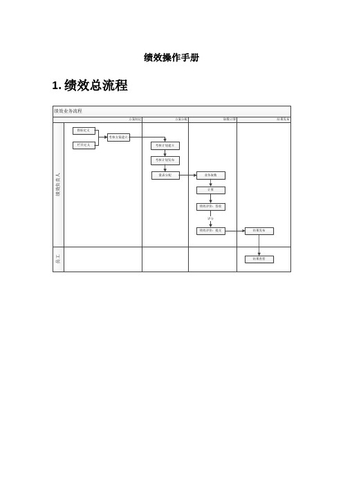
2.日常业务2.1.基础设置2.1.1.核算科室类别●核算科室类别编码需符合编码规则。
●核算科室引用核算科室类别。
●绩效系统和奖金系统共用核算科室类别档案。
●核算科室可从HRP系统中导入,也可EXCEL导入。
●核算科室如果要在量表分配中使用,负责人必须录入,否则不可见。
●绩效系统和奖金系统共用核算科室档案。
2.1.3.核算科室人员●可EXCEL批量导入。
●支持同步HRP人员档案。
●支持批改。
在绩效考核中,考核是以岗位体系关系进行考核,比如上下级的隶属关系,在此设置考核关系,这样在后续步骤中可以找到相应的人员,同时也可以指定人员进行操作。
●通过工具栏中的〖同步〗、〖导入〗、〖增加〗可设定岗位序列从而设定考核关系,可对已有的岗位序列进行增加、修改、删除。
但是需要符合编码方案,编码方案在界面中显示,通过相应的编码层级体现编码方案,变更后的岗位序列在左树目录下可看到,选择不同的岗位序列名称可看到在此序列下对应的岗位体系●岗位序列在人事系统中维护。
●可手工新增,岗位参照人事系统基础档案的岗位。
●可直接同步人事系统基础档案的岗位。
●可通过EXCEL导入,系统提供EXCEL导入模版。
2.1.5.维度设置●系统预置九类考核维度,后续的考核评价选用此维度设置。
●指标评价人:在考核方案的考核维度中,选择指标评价人,则量表分配生成量表时,系统将指标档案中定义的评价人为此指标的评价人。
2.1.6.评分方式●分为数值式和等级式●系统预置百分制、十分制、五分制。
●若评分方式已被后续业务引用,则不许删除此种评分方式。
●若后续的计划发布,则其引用的评分方式则不允许修改。
●标准值用来做等级式和百分式的换算。
系统内部换算按照百分制进行。
对于数值式评分方式,与百分制的换算根据定义的最大、最小值按比例进行;对于等级式评分方式,等级向百分制的转换,按照各等级中定义的标准值及所有等级上下限的取值极限范围等比例换算;百分制向等级的转换,按照百分制分数落在等级上下限范围所对应的等级确定。
HRPWM
TMS320x28xx,28xxx High-Resolution Pulse Width Modulator(HRPWM)Reference GuideLiterature Number:SPRU924BApril2005–Revised September20072SPRU924B–April2005–Revised September2007Submit Documentation FeedbackPreface (5)1Introduction (9)2Operational Description of HRPWM (10)2.1Controlling the HRPWM Capabilities (10)2.2Configuring the HRPWM (12)2.3Principle of Operation (12)2.4Scale Factor Optimizing Software(SFO) (16)2.5HRPWM Examples Using Optimized Assembly Code (21)3HRPWM Register Descriptions (27)3.1Register Summary (27)3.2Registers and Field Descriptions (28)Appendix A Revision History (30)Appendix B SFO Library Software-SFO_TI_Build_V5.lib (31)B.1SFO Library Version Comparison (31)B.2Software Usage (34)SPRU924B–April2005–Revised September2007Table of Contents3 Submit Documentation FeedbackList of Figures1Resolution Calculations for Conventionally Generated PWM (9)2Operating Logic Using MEP (10)3HRPWM Extension Registers and Memory Configuration (11)4HRPWM System Interface (11)5Required PWM Waveform for a Requested Duty=40.5% (13)6Low%Duty Cycle Range Limitation Example When PWM Frequency=1MHz (15)7High%Duty Cycle Range Limitation Example when PWM Frequency=1MHz (16)8Simple Buck Controlled Converter Using a Single PWM (22)9PWM Waveform Generated for Simple Buck Controlled Converter (22)10Simple Reconstruction Filter for a PWM Based DAC (24)11PWM Waveform Generated for the PWM DAC Function (24)12HRPWM Configuration Register(HRCNFG) (28)13Counter Compare A High Resolution Register(CMPAHR) (28)14TB Phase High Resolution Register(TBPHSHR) (29)List of Tables1Resolution for PWM and HRPWM (9)2HRPWM Registers (10)3Relationship Between MEP Steps,PWM Frequency and Resolution (12)4CMPA vs Duty(left),and[CMPA:CMPAHR]vs Duty(right) (13)5Duty Cycle Range Limitation for3and6SYSCLK/TBCLK Cycles (16)6SFO Library Routines (17)7Factor Values (18)8Register Descriptions (27)9HRPWM Configuration Register(HRCNFG)Field Descriptions (28)10Counter Compare A High Resolution Register(CMPAHR)Field Descriptions (28)11TB Phase High Resolution Register(TBPHSHR)Field Descriptions (29)A-1Changes Made in Revision B (30)B-1SFO Library Version Comparison (31)B-2SFO V5Library Routines (32)B-3Software Functions (34)4List of Figures SPRU924B–April2005–Revised September2007Submit Documentation FeedbackPrefaceSPRU924B–April2005–Revised September2007About This ManualThis document describes the operation of the high-resolution extension to the pulse width modulator(HRPWM).Notational ConventionsThis document uses the following conventions.•Hexadecimal numbers are shown with the suffix h.For example,the following number is40 hexadecimal(decimal64):40h.•Registers in this document are shown in figures and described in tables.–Each register figure shows a rectangle divided into fields that represent the fields of the register.Each field is labeled with its bit name,its beginning and ending bit numbers above,and itsread/write properties below.A legend explains the notation used for the properties.–Reserved bits in a register figure designate a bit that is used for future device expansion.Related Documentation From Texas InstrumentsThe following documents describe the C2000™devices and related support tools.Copies of thesedocuments on the Internet at .Tip:Enter the literature number in the search box provided atThe current documentation that describes the C2000and other technicalcollateral,is available in the C2000DSP product folder at:Data Manuals—contains the pinout,signal descriptions,as well as electrical and timing specifications for the F280xdevices.SPRS357—contains the pinout,signal descriptions,as well as electrical and timing specifications for theF28044device.SPRS439—contains the pinout,signal descriptions,as well as electrical and timing specifications for theF2833x devices.CPU User's Guides—SPRU430—describes the central processing unit(CPU)and the assembly language instructions of theTMS320C28x fixed-point digital signal processors(DSPs).It also describes emulation featuresavailable on these DSPs.SPRUEO2—describes the floating-point unit and includes the instructions for the FPU.Peripheral Guides—SPRU566—SPRU924B–April2005–Revised September2007Preface5 Submit Documentation Feedback Related Documentation From Texas Instrumentsdescribes the peripheral reference guides of the28x digital signal processors(DSPs).SPRUFB0—TMS320x2833x System Control and Interrupts Reference Guidedescribes the various interrupts and system control features of the2833x digital signal controllers(DSCs).SPRU712—describes the various interrupts and system control features of the280x digital signal processors(DSPs).SPRU812—describes how to configure and use the on-chip ADC module,which is a12-bit pipelined ADC.SPRU716—describes how to configure and use the on-chip ADC module,which is a12-bit pipelined ADC.SPRU949—describes the XINTF,which is a nonmultiplexed asynchronous bus,as it is used on the2833xdevices.SPRU963—describes the purpose and features of the bootloader(factory-programmed boot-loading software)and provides examples of code.It also describes other contents of the device on-chip boot ROMand identifies where all of the information is located within that memory.SPRU722—describes the purpose and features of the bootloader(factory-programmed boot-loading software).It also describes other contents of the device on-chip boot ROM and identifies where all of theinformation is located within that memory.SPRUFB7—describes the McBSP available on the F2833x devices.The McBSPs allow direct interface betweena DSP and other devices in a system.SPRUFB8—describes the DMA on the2833x devices.SPRU791—describes the main areas of the enhanced pulse width modulator that include digital motor control,switch mode power supply control,UPS(uninterruptible power supplies),and other forms of powerconversion.SPRU924—describes the operation of the high-resolution extension to the pulse width modulator(HRPWM).SPRU807—describes the enhanced capture module.It includes the module description and registers.SPRU790—describes the eQEP module,which is used for interfacing with a linear or rotary incrementalencoder to get position,direction,and speed information from a rotating machine in highperformance motion and position control systems.It includes the module description and registers.SPRU074—describes the eCAN that uses established protocol to communicate serially with other controllers inelectrically noisy environments.SPRU051—6Read This First SPRU924B–April2005–Revised September2007Submit Documentation FeedbackRelated Documentation From Texas Instruments describes the SCI,which is a two-wire asynchronous serial port,commonly known as a UART.TheSCI modules support digital communications between the CPU and other asynchronous peripheralsthat use the standard non-return-to-zero(NRZ)format.SPRU059—describes the SPI-a high-speed synchronous serial input/output(I/O)port-that allows a serial bitstream of programmed length(one to sixteen bits)to be shifted into and out of the device at aprogrammed bit-transfer rate.SPRU721—describes the features and operation of the inter-integrated circuit(I2C)module that is available onthe TMS320x280x digital signal processor(DSP).Tools Guides—SPRU513—describes the assembly language tools(assembler and other tools used to develop assemblylanguage code),assembler directives,macros,common object file format,and symbolic debuggingdirectives for the TMS320C28x device.SPRU514—describes the TMS320C28x™C/C++compiler.This compiler accepts ANSI standard C/C++sourcecode and produces TMS320DSP assembly language source code for the TMS320C28x device.SPRU608—describes the simulator,available within the Code Composer Studio for TMS320C2000IDE,thatsimulates the instruction set of the C28x™core.SPRU625—describes development using DSP/BIOS.TrademarksC2000,TMS320C28x,C28x are trademarks of Texas Instruments.SPRU924B–April2005–Revised September2007Read This First7 Submit Documentation FeedbackReference GuideSPRU924B–April2005–Revised September2007This document is used in conjunction with the28xxx Enhanced Pulse Width Modulator (ePWM)Module Reference Guide(literature numberThe HRPWM module extends the time resolution capabilities of the conventionally derived digital pulse width modulator(PWM).HRPWM is typically used when PWM resolution falls below~9-10bits.This occurs at PWM frequencies greater than~200kHz when using a CPU/system clock of100MHz.The key features of HRPWM are:•Extended time resolution capability•Used in both duty cycle and phase-shift control methods•Finer time granularity control or edge positioning using extensions to the Compare A and Phase registers•Implemented using the A signal path of PWM,i.e.,on the EPWMxA output.EPWMxB output has conventional PWM capabilities•Self-check diagnostics software mode to check if the micro edge positioner(MEP)logic is running optimallyTopic Page8SPRU924B–April2005–Revised September2007 High-Resolution Pulse Width Modulator(HRPWM)Submit Documentation Feedback1IntroductionPWMt/F x 100%PWM SYSCLKOUT(F/F)2PWM SYSCLKOUTIntroductionThe ePWM peripheral is used to perform a function that is mathematically equivalent to a digital-to-analog converter(DAC).As shown in Figure1,where T SYSCLKOUT=10ns(i.e.100MHz clock),the effectiveresolution for conventionally PWM is a function of PWM frequency(or period)and system clock frequency.Figure1.Resolution Calculations for Conventionally Generated PWM If the required PWM operating frequency does not offer sufficient resolution in PWM mode,you may want to consider HRPWM.As an example of improved performance offered by HRPWM,Table1showsresolution in bits for various PWM frequencies.Table1values assume a MEP step size of180ps.See the device data sheet for typical and maximum performance specifications for the MEP.Table1.Resolution for PWM and HRPWMPWM Regular Resolution(PWM)High Resolution(HRPWM)Freq Bits%Bits%(kHz)2012.30.018.10.0005011.00.016.80.00110010.00.115.80.0021509.40.215.20.0032009.00.214.80.0042508.60.314.40.0055007.60.513.80.0071000 6.6 1.012.40.0181500 6.1 1.511.90.0272000 5.6 2.011.40.036 Although each application may differ,typical low frequency PWM operation(below250kHz)may notrequire HRPWM.HRPWM capability is most useful for high frequency PWM requirements of powerconversion topologies such as:•Single-phase buck,boost,and flyback•Multi-phase buck,boost,and flyback•Phase-shifted full bridge•Direct modulation of D-Class power amplifiersSPRU924B–April2005–Revised September2007High-Resolution Pulse Width Modulator(HRPWM)9 Submit Documentation Feedback2Operational Description of HRPWM PWM duty(0 to 1.0 in Q15 format)PWM period (N CPU cycles)MEP scale factor Number of MEP steps in one coarse step16−bit CMPA register value16−bit CMPAHR register value= number of coarse steps = (number of MEP steps) << 8 + 0x180 (rounding)†Number of coarse steps Number of MEP steps = integer(PWMduty * PWMperiod)= fraction(PWMduty * PWMperiod) * (MEPScaleFactor)†For MEP range and rounding adjustment.2.1Controlling the HRPWM CapabilitiesOperational Description of HRPWMThe HRPWM is based on micro edge positioner (MEP)technology.MEP logic is capable of positioning an edge very finely by sub-dividing one coarse system clock of a conventional PWM generator.The time step accuracy is on the order of 150ps.The HRPWM also has a self-check software diagnostics mode tocheck if the MEP logic isrunning optimally,under all operating conditions.Details on software diagnostics and functions are in Section 2.4.Figure 2shows the relationship between one coarse system clock and edge position in terms of MEPsteps,which are controlled via an 8-bit field in the Compare A extension register (CMPAHR).Figure 2.Operating Logic Using MEPTo generate an HRPWM waveform,configure the TBM,CCM,and AQM registers as you would togenerate a conventional PWM of a given frequency and polarity.The HRPWM works together with theTBM,CCM,and AQM registers to extend edge resolution,and should be configured accordingly.Although many programming combinations are possible,only a few are needed and practical.These methods are described in Section 2.5.Registers discussed but not found in this document can be seen in 28xxx Enhanced Pulse Width Modulator (ePWM)Module Reference Guide (literature number The HRPWM operation is controlled and monitored using the following registers:Table 2.HRPWM RegistersmnemonicAddress Offset Shadowed Description TBPHSHR0x0002No Extension Register for HRPWM Phase (8bits)CMPAHR0x0008Yes Extension Register for HRPWM Duty (8bits)HRCNFG (1)0x0020No HRPWM Configuration Register (1)This register is EALLOW protected.The MEP of the HRPWM is controlled by two extension registers,each 8-bits wide.These two HRPWM registers are concatenated with the 16-bit TBPHS and CMPA registers used to control PWM operation.•TBPHSHR -Time Base Phase High Resolution Register•CMPAHR -Counter Compare A High Resolution Register10High-Resolution Pulse Width Modulator (HRPWM)SPRU924B–April 2005–Revised September 2007Submit Documentation FeedbackTBPHSHR (8)Reserved (8)TBPHS (16)0x00020x0003Reserved (8)TBPHSHR (8)TBPHS (16)31161587Single 32 bit writeReserved (8)CMPA (16)CMPAHR (8)0x00080x0009Single 32 bit writeCMPA (16)31CMPAHR (8)Reserved (8)161587EPWMxSYNCIEPWMxSYNCOEPWMxAEPWMxB EPWMxTZINT TZ1 to TZ6EPWMxINT EPWMxSOCA EPWMxSOCB Operational Description of HRPWMFigure 3.HRPWM Extension Registers and Memory ConfigurationHRPWM capabilities are controlled using the Channel A PWM signal path.Figure 4shows how the HRPWM interfaces with the 8-bit extension registers.Figure 4.HRPWM System InterfaceSPRU924B–April 2005–Revised September 2007High-Resolution Pulse Width Modulator (HRPWM)11Submit Documentation Feedback2.2Configuring the HRPWM2.3Principle of Operation2.3.1Edge PositioningOperational Description of HRPWMOnce the ePWM has been configured to provide conventional PWM of a given frequency and polarity,the HRPWM is configured by programming the HRCNFG register located at offset address 20h.This register provides configuration options for the following key operating modes:Edge Mode —The MEP can be programmed to provide precise position control on the rising edge (RE),falling edge (FE)or both edges (BE)at the same time.FE and RE are used for power topologies requiring duty cycle control,while BE is used for topologies requiring phase shifting,e.g.,phase shifted full bridge.Control Mode —The MEP is programmed to be controlled either from the CMPAHR register (duty cyclecontrol)or the TBPHSHR register (phase control).RE or FE control mode should be used with CMPAHR register.BE control mode should be used with TBPHSHR register.Shadow Mode —This mode provides the same shadowing (double buffering)option as in regular PWMmode.This option is valid only when operating from the CMPAHR register and should be chosen to be the same as the regular load option for the CMPA register.If TBPHSHR is used,then this option has no effect.The MEP logic is capable of placing an edge in one of 255(8bits)discrete time steps,each of which has a time resolution on the order of 150ps.The MEP works with the TBM and CCM registers to be certain that time steps are optimally applied and that edge placement accuracy is maintainedover a wide range of PWM frequencies,system clock frequencies and other operating conditions.Table 3shows the typical range of operating frequencies supported by the HRPWM.Table 3.Relationship Between MEP Steps,PWM Frequency and ResolutionSystem MEP Steps Per PWM MIN PWM MAX Res.@MAX (MHz)SYSCLKOUT (1)(2)(3)(Hz)(4)(MHz)(Bits)(5)50.0111763 2.5011.160.093916 3.0010.970.0791068 3.5010.680.0691221 4.0010.490.0621373 4.5010.3100.05615265.0010.1(1)System frequency =SYSCLKOUT,i.e.CPU clock.TBCLK =SYSCLKOUT.(2)Table data based on a MEP time resolution of 180ps (this is an the TMS320F2808,TMS320F2806,TMS320F2801Digital Signal Processors Data Manual [literature number (3)MEP steps applied =T SYSCLKOUT /180ps in this example.(4)PWM minimum frequency is based on a maximum period value,i.e.TBPRD =65535.PWM mode is asymmetrical up-count.(5)Resolution in bits is given for the maximum PWM frequency stated.In a typical power control loop (e.g.,switch modes,digital motor control [DMC],uninterruptible power supply [UPS]),a digital controller (PID,2pole/2zero,lag/lead,etc.)issues a duty command,usuallyexpressed in a per unit or percentage terms.Assume that for a particular operating point,the demanded duty cycle is 0.405or 40.5%on time and the required converter PWM frequency is 1.25MHz.Inconventional PWM generation with a system clock of 100MHz,the duty cycle choices are in the vicinity of 40.5%.In Figure 5,a compare value of 32counts (i.e.duty =40%)is the closest to 40.5%that you can attain.to an edge position of 320ns instead of the desired 324ns.This data is shown in Table 4.By utilizing the MEP,you can achieve an edge position much closer to the desired point of 324ns.Table 4shows that in addition to the CMPA value,22steps of the MEP (CMPAHR register)will position at 323.96ns,resulting in almost zero error.In this example,it is assumed that the MEP has a step resolution of 180ns.12High-Resolution Pulse Width Modulator (HRPWM)SPRU924B–April 2005–Revised September 2007Submit Documentation FeedbackDemanded duty (40.5%)EPWM1A2.3.2Scaling ConsiderationsOperational Description of HRPWMFigure 5.Required PWM Waveform for a Requested Duty =40.5%Table 4.CMPA vs Duty (left),and [CMPA:CMPAHR]vs Duty (right)CMPA (count)(1)(2)(3)DUTY High CMPA CMPAHR Duty High %Time (count)(count)(%)Time (ns)(ns)2835.028*******.405323.242936.3290321940.428323.423037.5300322040.450323.603138.8310322140.473323.783240.0320322240.495323.963341.3330322340.518324.143442.5340322440.540324.32322540.563324.50Required 322640.585324.6832.4040.5324322740.608324.86(1)System clock,SYSCLKOUT and TBCLK =100MHz,10ns(2)For a PWM Period register value of 80counts,PWM Period =80x 10ns =800ns,PWM frequency =1/800ns =1.25MHz (3)Assumed MEP step size for the above example =180psTMS320F2806,TMS320F2801/UCD9501Digital Signal Processors Data Manual (literature number for typical and maximum MEP values.The mechanics of how to position an edge precisely in time has been demonstrated using the resources of the standard (CMPA)and MEP (CMPAHR)registers.In a practical application,however,it is necessary to seamlessly provide the CPU a mapping function from a per-unit (fractional)duty cycle to a final integer (non-fractional)representation that is written to the [CMPA:CMPAHR]register combination.To do this,first examine the scaling or mapping steps involved.It is common in control software to express duty cycle in a per-unit or percentage basis.This has the advantage of performing all needed math calculations without concern for the final absolute duty cycle,expressed in clock counts or high time in ns.Furthermore,it makes the code more transportable across multiple converter types running different PWM frequencies.To implement the mapping scheme,a two-step scaling procedure is required.SPRU924B–April 2005–Revised September 2007High-Resolution Pulse Width Modulator (HRPWM)13Submit Documentation Feedback Operational Description of HRPWMAssumptions for this example:System clock,SYSCLKOUT=10ns(100MHz)PWM frequency= 1.25MHz(1/800ns)Required PWM duty cycle,PWMDuty=0.405(40.5%)PWM period in terms of coarse steps,=80PWMperiod(800ns/10ns)Number of MEP steps per coarse step at=55180ps(10ns/180ps),MEP_SFValue to keep CMPAHR within the rangeof1-255and fractional rounding constant(default value)=0180hStep1:Percentage Integer Duty value conversion for CMPA registerCMPA register value=int(PWMDuty*PWMperiod);int means integer part=int(0.405*80)=int(32.4)CMPA register value=32(20h)Step2:Fractional value conversion for CMPAHR registerCMPAHR register value=(frac(PWMDuty*PWMperiod)*MEP_SF)<<8)+0180h;frac means fractional part=(frac(32.4)*55<<8)+0180h;Shift is to move the valueas CMPAHR high byte=((0.4*55)<<8)+0180h=(22<<8)+0180h=22*256+0180h;Shifting left by8is the samemultiplying by256.=5632+0180h=1600h+0180hCMPAHR value=1780h;CMPAHR value=1700h,lower8bits will beignored by hardware.14SPRU924B–April2005–Revised September2007 High-Resolution Pulse Width Modulator(HRPWM)Submit Documentation Feedback2.3.3Duty Cycle Range Limitation=Operational Description of HRPWMNote:The MEP scale factor (MEP_SF)varies with the system clock and DSP operatingconditions.TI provides an MEP scale factor optimizing (SFO)software C function,which uses the built in diagnostics in each HRPWM and returns the best scale factor for a given operating point.The scale factor varies slowly over a limited range so the optimizing C function can be run very slowly in a background loop.The CMPA and CMPAHR registers are configured in memory so that the 32-bit data capability of the 280x CPU can write this as a single concatenated value,i.e.[CMPA:CMPAHR].The mapping scheme has been implemented in both C and assembly,as shown inSection 2.5.The actual implementation takes advantage of the 32-bit CPU architecture of the 28xx,and is somewhat different from the steps shown in Section 2.3.1.For time critical control loops where every cycle counts,the assembly version isrecommended.This is a cycle optimized function (11SYSCLKOUT cycles )that takes a Q15duty value as input and writes a single [CMPA:CMPAHR]value.In high resolution mode,the MEP is not active for 100%of the PWM period.It becomes operational:•3SYSCLK cycles after the period starts when diagnostics are disabled •6SYSCLK cycles after the period starts when SFO diagnostics are runningDuty cycle range limitations are illustrated in Figure 6.This limitation imposes a lower duty cycle limit on the MEP.For example,precision edge all the way down to 0%duty cycle.Although for the first 3or 6cycles,the HRPWM capabilities are not available,regular PWM duty control is still fully operational down to 0%duty.In most applications this should not be an issue as the controller regulation point is usually not designed to be close to 0%duty cycle.To better understand the useable duty cycle range,see Table 5.Figure 6.Low %Duty Cycle Range Limitation Example When PWM Frequency =1MHzSPRU924B–April 2005–Revised September 2007High-Resolution Pulse Width Modulator (HRPWM)15Submit Documentation Feedback30 ns2.4Scale Factor Optimizing Software (SFO)Operational Description of HRPWMTable 5.Duty Cycle Range Limitation for 3and 6SYSCLK/TBCLK CyclesPWM Frequency (1)3Cycles 6Cycles (kHz)Minimum DutyMinimum Duty2000.6% 1.4%400 1.2% 2.8%600 1.8% 4.2%800 2.4% 5.6%1000 3.0%7.0%1200 3.6%8.4%1400 4.2%9.8%1600 4.8%11.2%1800 5.4%12.6%20006.0%14.0%(1)System clock -T SYSCLKOUT =10ns System clock =TBCLK =100MHzIf the application demands HRPWM operation in the low percent duty cycle region,then the HRPWM can be configured to operate in count-down mode with the rising edge position (REP)controlled by the MEP.This is illustrated in Figure 7.In this case low percent duty limitation is no longer an issue.However,there will be a maximum duty limitation with same percent numbers as given in Table 5.Figure 7.High %Duty Cycle Range Limitation Example when PWM Frequency =1MHzThe micro edge positioner (MEP)logic is capable of placing an edge in one of 255discrete time steps.As previously mentioned,the size of these steps is on the order of 150ps.The MEP step size varies based on worst-case process parameters,operating temperature,and voltage.MEP step size increases with decreasing voltage and increasing temperature and decreases with increasing voltage and decreasing temperature.Applications that use the HRPWM feature should use the TI-supplied MEP scale factor optimizer (SFO)software functions.SFO functions help to dynamically determine the number of MEP steps per SYSCLKOUT period while the HRPWM is in operation.To utilize the MEP capabilities effectively during the Q15duty to [CMPA:CMPAHR]mapping function (see Section 2.3.2),the correct value for the MEP scaling factor (MEP_SF)needs to be known by the software.this,each HRPWM module has built in self-check and diagnostics capabilities that can be used to determine the optimum MEP_SF value for any operating condition.TI provides a C-callable library containing two SFO functions that utilize this hardware and determine the optimum MEP_SF.As such,MEP Control and Diagnostics registers are reserved for TI use.16High-Resolution Pulse Width Modulator (HRPWM)SPRU924B–April 2005–Revised September 2007Submit Documentation FeedbackOperational Description of HRPWM Currently,there are two released versions of the SFO library-SFO_TI_Build.lib and SFO_TI_Build_V5.lib.Versions2,3,and4were TI Internal only.A detailed description of the SFO_TI_Build.lib softwarefunctions follows rmation on the SFO_TI_Build_V5.lib software functions,which support up to 16HRPWM channels,can be found in Appendix B,along with a high-level comparison table between the two library versions.Note:For the F2833x floating point devices,when compiling application code for floating point(fpu32mode),libraries utilized by the application code must also be compiled for floatingpoint.The SFO_TI_Build_fpu.lib and SFO_TI_Build_V5_fpu.lib are available as thefloating point compiled equivalents to the fixed point SFO_TI_Build.lib andSFO_TI_Build_V5.lib libraries.The SFO functions in the fpu-version libraries areC-code-compatible to their fixed-point equivalents.Table6provides functional descriptions of the two SFO library routines in SFO_TI_Build.lib.Table6.SFO Library RoutinesFunction DescriptionSFO_MepDis(n)Scale Factor Optimizer with MEP DisabledThis routine runs faster,as the calibration logic works when HRPWM capabilities are disabled;therefore,HRPWM capabilities cannot be run concurrently when the ePWMn is being used.If SYSCLKOUT=TBCLK=100MHz and assuming MEP steps size is150psTypical value at100MHz=66MEP steps per unit TBCLK(10ns)The function returns a value in the variable array:MEP_ScaleFactor[n]=Number of MEP steps/SYSCLKOUTIf TBCLK is not equal to SYSCLKOUT,then the returned value must be adjusted to reflect the correct TBCLK:MEP steps per TBCLK=MEP_ScaleFactor[n]*(SYSCLKOUT/TBCLK)(1)Example:If TBCLK=SYSCLKOUT/2,MEP steps per TBCLK=MEP_ScaleFactor[n]*(100/50)=66*2=132(1)Constraints when using this function:SFO_MepDis(n)can be used with SYSCLKOUT from50MHz to100MHz(or maximum SYSCLK frequency).MEP diagnostics logic uses SYSCLKOUT not TBCLK and hence SYSCLKOUT restriction is an importantconstraint.SFO_MepDis(n)function does not require a starting Scale Factor value.When to useIf one of the ePWM modules is not used in HRPWM mode,then it can be dedicated to run the SFO diagnosticsfor the modules that are running HRPWM mode.Here the single MEP_SF value obtained can be applied toother ePWM modules.This assumes that all HRPWM module’s MEP steps are similar but may not be identical.The ePWM module that is not active in HRPWM mode is still fully operational in conventional PWM mode andcan be used to drive PWM pins.The SFO function only makes use of the MEP diagnostics logic.The other ePWM modules operating in HRPWM mode incur only a3-cycle minimum duty limitation.SFO_MepEn(n)Scale Factor Optimizer with MEP EnabledThis routine runs slower as the calibration logic is used concurrently while HRPWM capabilities are being usedby the ePWM module.If SYSCLKOUT=TBCLK=100MHz and assuming MEP steps size is150psTypical value at100MHz=66MEP steps per unit TBCLK(10ns)The function returns a value in the variable array:MEP_ScaleFactor[n](1)=Number of MEP steps/SYSCLKOUT=Number of MEP steps/TBCLKConstraints when using this function:SFO_MepEn(n)function is restricted to be used with SYSCLKOUT of60MHz-100MHz(or maximum SYSCLKfrequency).MEP diagnostics logic uses SYSCLKOUT not TBCLK and hence SYSCLKOUT restriction is animportant constraint.SFO_MepEn(n)function does require a starting Scale Factor value.MEP_ScaleFactor[0]needs to be initialized to a typical MEP step size valueWhen to use(1)n is the ePWM module number on which the SFO function operates.e.g.,n=1,2,3,or4for the F2808.Check your device data manual for device configurations.SPRU924B–April2005–Revised September2007High-Resolution Pulse Width Modulator(HRPWM)17 Submit Documentation Feedback。
HRPWM用户手册(工具软件翻译)教学提纲
TMS320x280x, 2801x, 2804x High Resolution Pulse Width Modulator (HRPWM) 用户手册HRPWM手册部分翻译(软件翻译),辅助阅读原资料。
前言---51 介绍72 HPWM的操作描述92.1控制HRPWM性能102.2配置HRPWM 112.3HRPWM原理122.4比例因子优化软件(sfo)182.5HRPWM示例使用优化的汇编代码233. HRPWM寄存器说明293.1寄存器概要293.2寄存器和字段描述30附录A SFO Library Software - SFO_TI_Build_V5.lib 33A.1 SFO库版本比较33A.2 软件用法36附录B 修订历史41前言:关于本手册本文档描述了操作的高分辨率扩展脉宽调制器(HRPWM)。
HRPWM模块的描述是一种参考指南HRPWM 0。
看到TMS320x28xx,28 xxx DSP外围参考指南(SPRU566)列表中的所有设备和一个HRPWM模块相同的类型,来确定类型,以及之间的差异为一个列表特定于设备的差异在一个类型。
这个文档是结合使用特定于设备的增强脉宽调制器(ePWM)模块参考指南。
这个HRPWM模块扩展了时间分辨能力的传统派生数字脉冲宽度调制器(PWM)。
HRPWM通常用在当PWM分辨率低于~ 9 - 10位。
这发生在PWM频率大于~ 200千赫当使用一个CPU /系统时钟的100 MHz。
关键HRPWM的特点是:•长时间分辨能力•用于工作周期和移相控制方法细粒度控制或•时间边缘定位使用扩展比较和阶段寄存器使用一个信号•实现PWM的道路,也就是说,在EPWMxA输出。
EPWMxB产量传统PWM功能•自检诊断软件模式来检查微边缘定位器(MEP)逻辑是跑步最佳介绍ePWM的外围是用来执行一个函数,它在数学上是等价的,一个数模转换转换器(DAC)。
如图1所示,TSYSCLKOUT = 10纳秒(即100 MHz时钟),有效分辨率为常规生成PWM是一个函数的PWM频率(或时间)和系统时钟频率。
HRM中文操作维护手册-D3
9.5 整机报废……………………………………………………………...34
10 故障诊断………………………………………………………………….35
4
HRM02X/04X/07X 离子交换装置操作维护手册
HRM02X/04X/07X 离子交换装置 操作维护手册
10.1 概
述……………………………………… ………………………….35
7.3 与流体系统连接……………………………………………………...21
7.3.1 常规连接………………………………………………………..21
7.3.2 进口管路设计…….……………………………………………..21
7.3.3 出口管线………………………………………………………...21
7.3.4 油箱内部结构…………………………………………………...21
5.6 材料…………………………………………………………...………13
5.7 可选配件……………………………………………………………...14
6 分系统说明及安全系统………………………………………………….15
6.1 进油系统……………………………………………………………...15
6.2 驱动系统……………………………………………………………...16
8.2.4 调整排空时间………………………………………………….28
8.3 关机…………………………………………………………………...28
8.3.1 紧急关机………………………………………………………...29
8.4 设备复位……………………………………………….……………..29
9 维护保养………………………………………………………………….30
visual modflow用户手册[整理版]
![visual modflow用户手册[整理版]](https://img.taocdn.com/s3/m/762e19eb1711cc7931b716cf.png)
visual modflow用户手册[整理版] VisualMODFLOW专业地下水流动和污染物运移模拟的集成三维图形模拟环境Waterloo Hydrogeologic许可证Waterloo Hydrogeologic公司(WHI)保留这个软件复制品的所有权。
该许可证允许你在以下条件下使用该软件复制品:1、版权说明本软件受加拿大版权法和相关国际协定条款保护。
因此,你必须象对待一本书一样对待该软件,但有一例外。
为了让你能长期使本软件,保证你的投资不受损失。
Waterloo Hydrogeologic公司授权你可以复制软件的文档副本。
说该软件“象一本书”, Waterloo Hydrogeologic公司的意思是,比如,任何人可以使用该软件,并且它可以自由地从一台计算机移到另一台计算机上,只要它不是同时在两台计算机上使用。
正象一本书不能同时被不同地方的读者浏览一样。
特别是,你不能出售、出租、分发下一级许可、或租借本软件或其文档;在没有得到Waterloo Hydrogeologic公司书面同意以前不能对该软件或文献做篡改、修订、或摘用,包括,但不仅限于翻译、反编译、反汇编、或制造下游产品。
所提供的软件和文档包含有商业秘密,持证者同意在没有得到Waterloo Hydrogeologic公司书面同意以前不会将这些商业秘密对非持证者公开。
2、保证Waterloo Hydrogeologic公司保证,在正常使用情况下,从购买之日起30天内磁盘材料和文件在材料和制造工艺上不会受到损坏,一旦材料和制造工艺上有缺损,Waterloo Hydrogeologic公司将给你替换缺损的磁盘和文件。
该保证仅限于替换,并不包括其他的任何损伤,包括但不仅限于利润方面以及特别的、偶然性的、连续的,或其他相似的索赔。
3、弃权除如上所述以外,不管是该软件的研制者还是其它的个人或组织都没有权力代表他(他们)制定有关该软件的明确的或者是隐含的保证。
WinDump中文使手册

WinDump使用提示基本用法:windump [ -aBdDeflnNOpqRStvxX ] [ -c count ] [ -F file ] [ -i interface ] [ -m module ] [ -r file ] [ -s snaplen ] [ -T type ] [ -w file ] [ -E algo:secret ] [ expression ]主要参数有选项和表达式两类。
下面说明几个必要的选项和表达式:-i 指定要监听的网络接口,可以使用windump -D 列出当前系统中所有的网络设备接口,不指定的话是设备列表中找得的第一个。
例如:./WinDump.exe -D1."Device"NPF_GenericNdisWanAdapter (Generic NdisWan adapter)2."Device"NPF_{6AA36CF4-E4FD-49BF-93E5-DC29AB8A3AA5} (SiS NIC SISNIC (Microsoft' s Packet Scheduler) )则./WinDump.exe./WinDump.exe -i 1./WinDump.exe -i ""Device""NPF_GenericNdisWanAdapter都是监听第一个网络接口设备Generic NdisWan adapter。
./WinDump.exe -i 2./WinDump.exe -i ""Device""NPF_{6AA36CF4-E4FD-49BF-93E5-DC29AB8A3AA5}都是监听第二个网络接口设备SiS NIC SISNIC (Microsoft' s Packet Scheduler)。
如果不指定表达式,所有通过指定接口的packet都输出,否则只把表达式expression为真的输出。
WPM使用说明
WPM参数管理系统软件安装及登录1.登陆http://10.224.133.139 ,下载Cllient.zip压缩包后解压缩并按照提示安装WPM2.安装完成后,运行“WPM”程序,在弹出的WPM登陆界面中输入用户名:Administrator(A大写),密码:11111111,服务器地址:10.224.133.139,连接:直接连接WPM界面介绍登录WPM后,客户端界面如图1所示,WPM界面说明请参见表1。
图1 WPM客户端界面客户端界面中的菜单栏是系统的主菜单,按照系统的主要功能进行组织。
工具栏客户端界面中工具栏提供了一些常用操作的入口,通过单击对应的快捷图标,可以快速进入相关的窗口或者执行相关操作。
查询配置参数WPM可以查询以下配置参数:●GSM网络BSC配置参数、BTS配置参数、小区配置参数和TRX配置参数。
●TD-SCDMA网络RNC配置参数、NodeB配置参数、小区配置参数、Carrier配置参数和信道配置参数。
您可以根据需要查询指定网元或信道配置参数的现网值和规划值以及相关信息。
操作步骤1.根据参数查询结果的显示情况选择不同的菜单项。
2.选择“制式”和“网元类型”。
3.根据需要执行以下操作。
o您可以设置过滤条件,方便快速的查找所需的网元。
4.单击“参数”页签,根据需要执行以下操作。
o您可以设置过滤条件,方便快速的查找所需的参数。
说明:可以单击“保存为模板”保存参数查询方案为.xml文件。
5.单击“执行”。
操作结果选择“查询 > 参数查询 > 参数显示在行”菜单查询时,查询结果显示为上下两部分:上半部分为显示参数在系统的取值,下半部分显示参数的修改记录。
选择上半部分任意一条查询结果,联动显示该参数的修改记录。
查询结果说明后续处理过滤查询结果您可以在每一列的模糊查询框中输入查询条件,对查询结果进行过滤。
∙分组查询结果您可以拖动某一列至分组区域框,完成按列分组。
如果拖动多列至分组区域框,则按拖动列的顺序级联显示。
海地软件使用说明
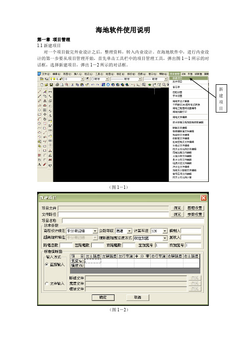
海地软件使用说明第一章项目管理1.1新建项目对一个项目做完外业设计之后,整理资料,转入内业设计。
在海地软件中,进行内业设计的第一步要从项目管理开始,首先单击工具栏中的项目管理工具,弹出图1-1所示的对话框,选择新建项目,弹出1-2所示的对话框。
(图1-1)(图1-2)在图1-2所示的对话框中,依次填写项目文件、文件路径、项目名称、技术参数、标准横断面等内容。
具体的填写方法为:1、输入项目文件:根据各年完成的项目,我们把每次完成的项目有条不紊的统计分类在相应的硬盘目录下,既将各年的项目分类保存在一起。
例如:我们要做一条2007年完成的英武至柏果的公路项目设计,首先建立项目文件夹,打开D :公路\2007年完成,新建一个文件夹,将文件夹命名为:英武至柏果公路。
然后在海地软件项目管理――新建项目中打开图1-2所示的界面,从项目文件――浏览中打开建立好的英武至柏果公路文件夹,在输入项目文件名对话框中输入项目名称,选择保存即可,如图1-3(图1-3)2、输入技术参数:根据项目的等级,输入相应的技术参数。
其中新建项目的高程设计线在路基边缘,超高旋转轴在内侧行车道边缘,老路改造项目的高程设计线在路基中线,超高旋转轴在内侧行车道边缘。
四级公路的计算车速为20Km/小时。
3编辑器里编辑如图1-4,1-5右行车道、右路肩,一般路幅数为4幅)格式为:起点桩号 左土路肩宽度 左行车道宽度 右行车道宽度 右土路肩宽度;终点桩号 左土路肩宽度 左行车道宽度 右行车道宽度 件输入格式为:起点桩号 左土路肩横披 左行车道横披 右行车道横披 右土路肩横披;终点桩号 左土路肩横披 左行车道横披 右行车道横披 右土路肩横披,横披单位为%,输完之后(图1-4)(图1-5)第二章平面2.1 交点线文件输入:交点线文件输入有2如图2-1号、来向边长、去向偏角、圆曲线半径等内容,1、角度(方位角、偏角)用度(D)、分(F)、秒(M)的拼音的第一个字母表示,如:30D45F56.78M,表示30度45分56.78秒。
- 1、下载文档前请自行甄别文档内容的完整性,平台不提供额外的编辑、内容补充、找答案等附加服务。
- 2、"仅部分预览"的文档,不可在线预览部分如存在完整性等问题,可反馈申请退款(可完整预览的文档不适用该条件!)。
- 3、如文档侵犯您的权益,请联系客服反馈,我们会尽快为您处理(人工客服工作时间:9:00-18:30)。
TMS320x280x, 2801x, 2804x High Resolution Pulse Width Modulator (HRPWM) 用户手册HRPWM手册部分翻译(软件翻译),辅助阅读原资料。
前言---51 介绍72 HPWM的操作描述92.1控制HRPWM性能102.2配置HRPWM 112.3HRPWM原理122.4比例因子优化软件(sfo)182.5HRPWM示例使用优化的汇编代码233. HRPWM寄存器说明293.1寄存器概要293.2寄存器和字段描述30附录A SFO Library Software - SFO_TI_Build_V5.lib 33A.1 SFO库版本比较33A.2 软件用法36附录B 修订历史41前言:关于本手册本文档描述了操作的高分辨率扩展脉宽调制器(HRPWM)。
HRPWM模块的描述是一种参考指南HRPWM 0。
看到TMS320x28xx,28 xxx DSP外围参考指南(SPRU566)列表中的所有设备和一个HRPWM模块相同的类型,来确定类型,以及之间的差异为一个列表特定于设备的差异在一个类型。
这个文档是结合使用特定于设备的增强脉宽调制器(ePWM)模块参考指南。
这个HRPWM模块扩展了时间分辨能力的传统派生数字脉冲宽度调制器(PWM)。
HRPWM通常用在当PWM分辨率低于~ 9 - 10位。
这发生在PWM频率大于~ 200千赫当使用一个CPU /系统时钟的100 MHz。
关键HRPWM的特点是:•长时间分辨能力•用于工作周期和移相控制方法细粒度控制或•时间边缘定位使用扩展比较和阶段寄存器使用一个信号•实现PWM的道路,也就是说,在EPWMxA输出。
EPWMxB产量传统PWM功能•自检诊断软件模式来检查微边缘定位器(MEP)逻辑是跑步最佳介绍ePWM的外围是用来执行一个函数,它在数学上是等价的,一个数模转换转换器(DAC)。
如图1所示,TSYSCLKOUT = 10纳秒(即100 MHz时钟),有效分辨率为常规生成PWM是一个函数的PWM频率(或时间)和系统时钟频率。
设SYSCLKOUT=100MHZ TPWM=100KHZ 100K/100M*100%=0.1%如果所需的PWM操作频率不提供足够的决议在PWM方式,您可能想要考虑HRPWM。
作为一个例子,HRPWM提供改进的性能,表1显示了决议在比特数各种PWM频率。
这些值假设一个100 MHz SYSCLK频率和一个MEP步骤大小为180 ps。
看到特定于设备的数据表为典型的和最大的性能规范为MEP。
尽管每个应用程序可能不同,典型的低频率PWM操作(低于250千赫)可能不会需要HRPWM。
HRPWM能力是最有效的高频PWM要求的权力转换拓扑,例如:•单相巴克,提高,和反激变换器巴克•多阶段,提高,和反激变换器•相移全桥•直接调制的d类功率放大器2操作的描述HRPWM这个HRPWM是基于微边缘定位器(MEP)技术。
MEP的逻辑是,能够将一个边缘非常精细地按一个粗系统时钟可能分化的一个传统的PWM发生器。
时间步精度在订购150 ps。
看到特定于设备的数据表对于典型的MEP步长在特定的设备。
这个HRPWM也有自检软件诊断模式检查MEP逻辑运行优化,在所有的操作条件。
细节诊断和功能的软件第2.4节。
图2显示了一个粗之间的关系系统时钟和边缘位置的MEP而言步骤,通过一个8位字段控制在比较一个扩展注册(CMPAHR)。
生成一个HRPWM波形,配置TBM,CCM,如同你的包寄存器生成一个传统的PWM给定的频率和极性。
这个HRPWM一起工作TBM、CCM,寄存器来扩展包边的分辨率,并且应该相应地配置。
尽管许多编程组合都是可能的,只有少数是必要的和实用的。
这些方法第2.5节中描述。
寄存器讨论过,但发现在这个文档中可以看到特定于设备的增强的脉冲宽度调制器(ePWM)模块参考指南。
HRPWM的操作控制和监控使用以下登记:2.1控制HRPWM功能MEP的HRPWM是由两个扩展寄存器,每个8位宽。
这两个HRPWM寄存器是连接与16位TBPHS和衍生寄存器用来控制PWM操作。
•TBPHSHR -时间基础阶段高分辨率的寄存器•CMPAHR -计数器比较一个高分辨率的寄存器配置HRPWM一旦ePWM配置为提供传统的PWM给定的频率和极性,HRPWM配置通过编程使HRCNFG寄存器位于偏移地址20小时。
这个寄存器提供配置选项下面的关键操作模式:边缘模式——在同一时间,MPE可以通过编程提供精确位置控制的前沿(RE),下降沿(FE)或两个沿(BE)。
FE 和RE用于电力拓扑要求占空比控制,而BE用于拓扑要求移相,如移相全桥(PSFB)。
控制模式——MEP被编写为控制要么从CMPAHR寄存器(占空比控制)或TBPHSHR寄存器(相位控制)。
RE或FE控制模式应该使用CMPAHR寄存器。
BE控制模式应该使用TBPHSHR寄存器。
阴影模式-这种模式提供了相同的阴影(双缓冲)选项在普通PWM模式。
这个选项是有效的只有当操作从CMPAHR寄存器,应该选择同常规负载选项衍生寄存器。
如果TBPHSHR使用,那么这个选项没有任何影响。
2.3操作原理MEP逻辑能够把一个边缘在255(8比特)离散时间的步骤(参见特定于设备的数据表为典型的MEP步长)。
MEP 工程与TBM和CCM寄存器来确定时间步骤优化应用,边缘位置精度保持在一个广泛的PWM频率、系统时钟频率和其他操作条件。
表3显示了典型的范围的操作频率HRPWM支持的。
(1)系统频率= SYSCLKOUT,即CPU时钟。
TBCLK = SYSCLKOUT。
(2)表数据基于MEP时间分辨率为180 ps(这是一个示例值,请参见特定于设备的数据表为MEP限制。
(3)MEP步骤应用= TSYSCLKOUT / 180 ps在这个例子中。
(4)PWM最低频率是基于最大时间值,即TBPRD = 65535。
PWM方式是不对称来数。
(5)分辨率在比特了最大PWM频率表示。
2.3.1边缘定位在一个典型的功率控制回路(例如,开关模式,数字电动机控制(DMC)、不间断电源供应(UPS)、一个数字控制器(PID,2极/ 2 零,滞后/超前等)问题,通常一种责任命令表示在每单位或百分比。
假设为一个特定的操作点,要求工作周期是0.405或40.5%在时间和所需的变频器PWM频率是1.25 MHz。
在传统的PWM生成系统时钟的100 MHz,工作周期的选择是附近40.5%。
在图5中,一个比较值的32项(即,责任= 40%)是最接近40.5%,你可以实现。
这相当于一个320ns的边缘位置,而不是所需的324 ns。
此数据显示在表4。
利用MEP,您可以实现一个边缘位置更接近理想的角度324纳秒。
表4显示了,除了衍生价值,22个步骤的MEP(CMPAHR寄存器)将位置在323.96 ns边缘,导致几乎零错误。
在这个例子中,假定MEP有一个步骤分辨率为180 p。
(1)系统时钟,SYSCLKOUT和TBCLK = 100 MHz,10 ns(2)对于一个寄存器值80 PWM时期计数、PWM期= 80 x 10纳秒= 800 ns、PWM频率= 1/800 = 1.25 MHz ns(3)假设MEP步长对上述例子= 180 p看到特定于设备的数据手册典型和最大MEP值。
2.3.2缩放的考虑如何定位机制的优势恰恰在时间已经证明使用资源标准的衍生和MEP(CMPAHR)寄存器。
在实际应用中,然而,这是必要的能无缝地提供CPU映射函数从一个单位(分数)工作周期最后的整数(非小数)表示,被写到[衍:CMPAHR]寄存器组合。
要做到这一点,首先检查扩展或映射步骤。
这是常见的控制软件表达工作周期在一个单位或百分比的基础。
它的优点是执行所有的需要数学计算而无需关心最终绝对责任周期,表达了在时钟计数或高时间在ns。
此外,它使代码更移动式跨多个转换器运行不同的类型PWM频率。
实现映射方案,一个两步定标过程是必需的。
System clock , SYSCLKOUT = 10 ns (100 MHz)PWM frequency = 1.25 MHz (1/800 ns)Required PWM duty cycle, PWMDuty = 0.405 (40.5%)PWM period in terms of coarse steps, = 80PWMperiod (800 ns/10 ns)Number of MEP steps per coarse step at = 55180 ps (10 ns /180 ps ), MEP_ScaleFactorValue to keep CMPAHR within the range of1-255 and fractional rounding constant(default value) = 1.5 (0180h in Q8 format)步骤1:Percentage Integer Duty value conversion for CMPA registerCMPA register value = int(PWMDuty*PWMperiod); int means integer part(取整数部分)= int(0.405*80 )= int(32.4 )CMPA register value = 32 (20h)步骤2: Fractional value conversion for CMPAHR registerCMPAHR register value = (frac(PWMDuty*PWMperiod)*MEP_ScaleFactor+1.5) << 8); frac means fractional part= (frac(32.4) *55 + 1.5) <<8 Shift is to move the value as CMPAHR high byte= (0.4 * 55 + 1.5) <<8= (22 + 1.5) <<8= 23.5 * 256; Shifting left by 8 is the same as multiplying by 256.= 6016 CMPAHR value = 1780h CMPAHR value = 1700h , lower 8 bits will be ignored by hardware.(低8位被硬件忽略)注意:MEP比例因子(MEP_ScaleFactor)随系统时钟和DSP操作条件。
TI提供了一个MEP比例因子优化(SFO)软件C函数,它使用内置的诊断在每个HRPWM并返回最佳比例因子对于一个给定的操作点。