KGF40N120KDF TO-247规格书 KEC推荐
艾尔斯·科普科特冷凝式空气干燥器产品说明书
Why dry yourcompressed air?Compressed air contains oil, solid particles and water vapors. It is theinherent result of the compression process, which concentrates thenatural water vapors and particles in the air that surrounds us. Thisuntreated compressed air poses a substantial risk to your air system andend products. Its moisture content alone can cause corrosion in pipework, premature failure of pneumatic equipment, product spoilageand more. An air dryer is therefore essential to protect your systemsand processes.Refrigerant dryersby Atlas CopcoAtlas Copco’s refrigerant dryers provide the clean, dry air you need+) to expand the life of your equipment and ensure the quality of yourproducts. Our FD and FX dryers are designed in-house and tested usingthe most stringent methods. They meet or exceed the internationalstandards for compressed air purity and are tested according toISO 7183:2007.253614Controls the speed of the compressor to match your air demand and ensure the highest possible energy savings.1Opens the drain only when needed to eliminate unnecessary loss of compressed air during timed draining.4Counter-flow compact brazed plate or aluminum heat exchanger, with air-to-air side for optimum cooling efficiency and the lowest possible pressure drop.2®Touch controllerProvides advanced control and allows for remote monitoring.5Low velocity with high separation efficiency, even in low flow conditions.3Ensures plug-and-play installation.6VSD for superior energy savingsAtlas Copco’s in-house developed VSD technology matches your FD dryer’s power consumption to your production’s actual airflow. While a traditional refrigerant dryer can only be turned on or off, Atlas Copco’s FD VSD mirrors your production’s demand for compressed air as it fluctuates during the day, week or year. This ensures supreme energy savings as well as a stable dew point.Minimal environmental impactFD VSD dryers use the CFC-free R410A refrigerant, which has an ozone depletion potential (ODP) of zero. The refrigerant meets the strict F-Gas regulations and, due to its low powerconsumption, has an an outstanding TEWI (Total Equivalent Warming Impact) performance.Optimum performance and safety in all conditions• Hot gas bypass valve prevents freezing at lower loads.• The extremely reliable R410A rotary compressor provides the best performance with minimum environmental impact.Capillary tubes cope with all conditions – no moving parts for extra reliability.• Condenser with louvered fin technology for improved performance in dusty environments.Advanced remote monitoring and control• High-tech Elektronikon ® Touch controller with warning indications, dryer shutdown and maintenance scheduling. • Standard SMARTLINK remote monitoring to maximize air system performance and energy savings.Robust and compact design• Forklift opening for smooth transport. • Easy front and side panel access.• No bulky thermal mass heat exchanger needed to save on energy.FiltersIf your production requires higher levels of air quality andfiltration, UD + filters can be added on to your FD VSD dryer.Power consumptionVSD dryerFixed speed dryerSupreme energy efficiency• The FD offers a low pressure drop – typically below 0.2 bar/2.9 psi – and minimal energy consumption.• The compact brazed plate or aluminum heat exchanger was designed specifically to provide optimal pre-cooling and the lowest possible pressure drop.• The electronic no-loss condensate drain comes with a level sensor to open the drain only when needed, preventing unnecessary loss of compressed air.Comprehensive control and monitoring options• The Elektronikon ® Alpha controller displays the pressure dew point and relative humidity.• Remote alarm and start/stop control through voltage-free contact.• Additional features such as alarm history and standard remote visualization.Easy installation and long maintenance intervals• Small footprint thanks to an innovative all-in-one design. • Delivered ready for use, minimizing costly production downtime.Low environmental impactFD dryers use CFC-free refrigerants (R134A and R410A) with an ozone depletion potential (ODP) of zero.Counter-flow compact brazed plate or aluminum heatexchanger, with air-to-air side for optimum cooling efficiency and the lowest possible pressure drop.2condensate drainWith level sensor, backup manual drain and drain alarm.4separatorLasts longer thanks to limited vibrations, minimal moving parts, and reduced risk of leakage.1Reduces energy consumption and optimizes the pressure dew point at very low temperatures.5Low velocity with high separation efficiency even in low flow conditions.3Ensures stable pressure dew point and prevents freezing at lower loads.6connectionAllows for plug-and-play installation.8Eliminates the chance of moisture entering the compressed air system.7Reliable performance in tough conditions• Hot gas bypass valve prevents freezing at lower loads.• R134A piston compressor with high coefficient of performance (extremely reliableR410A rotary compressor for models FD 60-FD 95) provides the best performance with minimum environmental impact. Capillary tubes cope with all conditions – no moving parts for extra reliability.• Condenser with louvered fin technology for improved performance in dusty environments.3748152637481526Pressure dew point precisionThe FX comes in a wide range of sizes (7-300 l/s or 15-636 cfm) to offer a steady pressure dew point as low as +3°C/+37.4°F. Its easy to use digital display precision-measures and monitors the pressure dew point and dryer performance.Digital display• Pressure dew point: exact measurement and visual monitoring. • Status: refrigerant compressor and fan.• Alarms: high/low pressure dew point and probe failure.• Service warning.ReliableBuilt according to the stringent Atlas Copco standards, the FX is made of high quality, generously sized components.Hot environmentsHigh ambient temperatures can put your equipment to the test. The FX range offers several high temperature models that ensure dependable performance in conditions up to 46°C/115°F.Significant cost savings• Increased reliability and lifetime of tools and equipment.• Reduced pipe work leaks and thus a lower energy bill.• Less equipment breakdowns and operational interruptions.• Minimal chance of product damage as a result of moisture carryover.Sustainable refrigerantThe FX range comes with refrigerant that is compliant with F-Gas regulations to ensure the lowest possible carbon footprint and energy consumption.separatorNo chance of moisture entering the compressed air system.1Ensures stable pressure dew point and eliminates the possibility of condensate freezing.2Provides peace of mind through precise monitoring of pressure dew point.3connectionAllows for plug-and-play installation.4componentsFor straightforward servicing.5Offers high efficiency for better pressure dew point.6with integrated liquid separatorLasts longer thanks to limited vibrations, minimal moving parts, and reduced risk of leakage.8For a small footprint.7VSD:a game-changer in energy savingsWhen purchasing a refrigerant dryer, the main focus is usually on the initial cost. However, this only represents approximately 10% of the lifecycle cost of the dryer. Energy, maintenance and installation make up the bulk of your actual dryer costs. Direct and indirect (pressure drop) energy costs are the most important.Indirect energy costsIndirect energy costs are related to the extra energy your aircompressor must consume to overcome the pressure drop that takesplace in the air dryer. By design, Atlas Copco FD VSD dryers offer a lowpressure drop and efficient heat transfer – both of which contribute toFD VSD 100-300:Elektronikon ® Touch controller• 4.3-inch high-definition color display with clear pictograms and service indicator.• Internet-based dryer visualization using a simple Ethernet connection.• Automatic restart after voltage failure.• Built-in SMARTLINK online monitoring.• More flexibility: four different week schedules.• Graphical service plan indication.• Remote control and connectivity functions.SMARTLINK & Total ResponsibilityGet the most out of SMARTLINK as part of a Total Responsibility Plan. Step back, relax, and let our service engineers monitor your compressed air system. We know exactly when to serviceyour machines, diagnose any issues and be there on time to fix them.FD 5-95:Elektronikon ® Alpha controller• Exact measurement and visual monitoring of pressure dew point and ambient temperature.• High/low pressure dew point alarm.• Relative humidity indicator.• Energy saving mode.• Switch off at freezing alarm.• Alarm history and standard remote visualization.FX 1-16: Digital display• Pressure dew point: exact measurement and visual monitoring. • Energy saving mode.• Alarms: high/low pressure dew point and probe failure.•Service warnings.SMARTLINK: Data Monitoring ProgramSMARTLINK captures live data from your compressed air equipment and translates it in clear insights. At a glance, you can check uptime, energy efficiency and machine health.• Remote monitoring that helps you optimize your compressed air system and save energy and costs.• Provides a complete insight in your compressed air network.• Anticipates potential problems by warning you upfront.• Efficient service planning and parts handling to give you improved uptime.Advanced controlAtlas Copco’s refrigerant dryers are built to reliably and efficiently deliver quality air. But in the end, it’s all about how they perform on your work floor, meeting your individual needs and responding to your specific conditions. That is why the FD VSD, FD and FX come with comprehensive control options to allow you to get the best performance from your Atlas Copco dryer.Remote monitoringHow refrigerant dryers workA refrigerant dryer uses a refrigerant circuit and heat exchanger(s) to pre-coolair, refrigerate it to condense out moisture vapor, and then re-heat the air toAir circuit1Air-to-air heat exchanger: Incoming air is cooled downby the outgoing dry, cold air2Air-to-refrigerant heat exchanger: The air is cooled tothe required dew point by the refrigerant circuit. Thewater vapor condenses into water droplets3Integrated water separator: The moisture is collectedand evacuated by the electronic drainRefrigerant circuit4Refrigerant compressor: Compresses the gaseousrefrigerant to a higher pressure5Regulation device: The hot gas bypass valve regulatesthe dryer to prevent freezing at lower load conditions6Refrigerant condenser: Cools the refrigerant so that itchanges from a gas to a liquid7Refrigerant filter: Protects the expansion device fromharmful particles8Thermostatic expansion valve: The expansion processreduces the pressure and cools the refrigerant further9Liquid separator: Ensures that only refrigerant gasenters the compressorHot refrigerant gasCold refrigerant liquidExpanded refrigerant liquid2935 0868 41 © 2020, A t l a s C o p c o A i r p o w e r N V , B e l g i u m . A l l r i g h t s r e s e r v e d . D e s i g n s a n d s p e c i fi c h a n g e w i t h o u t n o t i c e o r o b l i g a t i o n . R e a d a l l s a f e t y i n s t r u c t i o n s i n t h e。
科肯H100A系列用户手册中文版
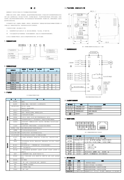
简介感谢您购买广州科肯电气有限公司生产的H100A 系列简易型变频器!H100A 实现了高转矩、高精度、宽调速驱动,满足通用变频器高性能化的趋势;具有超出同类产品的防跳闸性能和适应恶劣电网、温度、湿度和粉尘能力,极大提高产品可靠性。
灵活的输入输出端子、停电和停机参数存储选择、频率给定通道、主辅给定控制等,满足各种复杂高精度传动的要求,同时为设备制造业客户提供高集成度的一体化解决方案,对降低系统成本,提高系统可靠性具有极大价值。
本手册提供用户选型、安装配线、面板操作、参数设定、故障诊断等事项。
为确保能正确安装及操作H100A 系列变频器,请在装机之前,详细阅读本使用手册,并请妥善保存及交给本产品的使用者。
产品到货后在开箱时,请认真确认以下项目:1)本机铭牌的型号是否与您的订货一致。
箱内含您订购的机器、产品合格证、用户操作手册。
2)产品在运输过程中是否有破损现象;若发现有遗漏或损坏,请速与本公司或您的供货商联系解决。
由于致力于变频器的不断改善,因此本公司所提供的资料如有变更,恕不另行通知。
1.变频器型号说明2.变频器系列选型3.产品简介表1H100A 变频器技术规范4.产品外型图、安装孔位尺寸图图1H100A 变频器外型及安装孔位尺寸(mm )5.变频器配线说明图2H100A 变频器典型接线示意图5.1主电路端子及接线说明5.2控制端子及接线:表2H100A 变频器控制端子功能说明6.操作按键说明功能表中符号说明如下:“☆”:表示该参数的设定值在变频器处于停机、运行状态中,均可更改;“★”:表示该参数的设定值在变频器处于运行状态时,不可更改;“●”:表示该参数的数值是实际检测记录值,不能更改;。
KGF25N120KDA TO-247规格书 KEC推荐
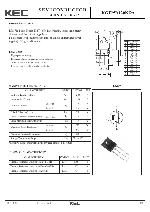
MAXIMUM RATING (Ta=25 )
CHARACTERISTIC Collector-Emitter Voltage Gate-Emitter Voltage @Tc=25 Collector Current @Tc=100 Pulsed Collector Current Diode Continuous Forward Current Diode Maximum Forward Current @Tc=25 Maximum Power Dissipation @Tc=100 Maximum Junction Temperature Storage Temperature Range Tj Tstg @Tc=100 ICM* IF IFM PD 91 150 -55 to + 150 W SYMBOL VCES VGES IC 25 75 25 75 227 A A A A W RATING 1200 20 50 UNIT Vevision No : 0
3/8
KGF25N120KDA
2013. 9. 30
Revision No : 0
4/8
KGF25N120KDA
2013. 9. 30
Revision No : 0
5/8
KGF25N120KDA
2013. 9. 30
Revision No : 0
VGE=VCE, IC=25mA VGE=15V, IC=25A
Collector-Emitter Saturation Voltage
VCE(sat)
VGE=15V, IC=25A, TC = 125 VGE=15V, IC=50A
Dynamic Total Gate Charge Gate-Emitter Charge Gate-Collector Charge Turn-On Delay Time Rise Time Turn-Off Delay Time Fall Time Turn-On Switching Loss Turn-Off Switching Loss Total Switching Loss Turn-On Delay Time Rise Time Turn-Off Delay Time Fall Time Turn-On Switching Loss Turn-Off Switching Loss Total Switching Loss Input Capacitance Ouput Capacitance Reverse Transfer Capacitance Short Circuit Withstand Time Qg Qge Qgc td(on) tr td(off) tf Eon Eoff Ets td(on) tr td(off) tf Eon Eoff Ets Cies Coes Cres tsc VCC=600V, VGE=15V, TC=100 VCE=30V, VGE=0V, f=1MHz VCC=600V, IC=25A, VGE=15V, RG=10 Inductive Load, TC = 125 10 2.0 1.6 3.6 2650 115 70 3450 mJ mJ mJ pF pF pF s VCC=600V, IC=25A, VGE=15V,RG=10 Inductive Load, TC = 25 1.85 0.9 2.75 40 30 180 190 2.4 1.2 3.6 mJ mJ mJ ns ns ns ns VCC=600V, VGE=15V, IC= 25A 160 25 80 40 25 175 85 nC nC nC ns ns ns ns
老肯低温等离子灭菌器参数100

老肯低温等离子灭菌器参数100老肯低温等离子灭菌器是一种专业用于医疗设备和器械的消毒设备,采用等离子技术,能够高效地杀灭微生物,确保医疗器械表面的无菌。
在使用老肯低温等离子灭菌器时,需要严格控制一些参数来保证有效的消毒过程。
参数设置1.温度控制:老肯低温等离子灭菌器的温度控制范围为20°C至60°C,最佳工作温度为40°C至45°C。
在消毒过程中,温度的稳定性对消毒效果至关重要,因此必须确保设备能够精确控制温度并保持在设定范围内。
2.气体流量:灭菌器中的等离子气体流量是影响消毒效果的关键参数之一。
一般而言,老肯低温等离子灭菌器的气体流量设置范围为1到5升/分钟,最佳设置为3升/分钟。
流量过高可能导致器械表面损伤,过低则无法达到有效消毒效果,因此需要根据具体情况进行合理调节。
3.压力控制:灭菌器的压力控制范围在0.2到0.5帕,根据不同的灭菌任务要求可以进行适当的调整。
过高或过低的压力都会影响等离子气体的均匀分布和气体与器械表面的接触效果,从而影响消毒效果。
4.处理时间:老肯低温等离子灭菌器的处理时间通常在30到60分钟不等,根据器械的类型和规格会有所不同。
在设定处理时间时,需考虑到灭菌器的预热时间和冷却时间,确保器械能够在适当的时间范围内完成消毒过程。
5.湿度控制:等离子消毒过程中的湿度控制也十分重要,一般设置在30%至60%之间。
湿度过高可能导致气体中水蒸汽含量过大,影响等离子反应的进行;湿度过低则可能降低等离子气体的传导性能,影响消毒效果。
6.气体种类:老肯低温等离子灭菌器可用的气体种类通常为氧气、氢气混合气。
不同气体种类的选择会影响消毒效果和速度,要根据具体的器械和消毒需求进行合理选择。
结语老肯低温等离子灭菌器作为一种高效、安全的消毒设备,通过合理设置各项参数,可以确保医疗器械表面的无菌状态。
在使用灭菌器时,操作人员需要严格按照要求调整参数,并定期对设备进行检查和维护,以保证消毒效果和器械的安全性。
充电缝包机好用吗
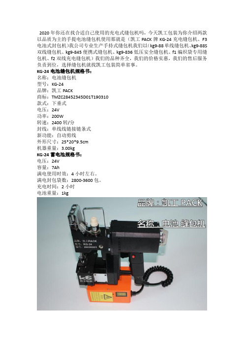
2020年你还在找合适自己使用的充电式缝包机吗,今天凯工包装为你介绍两款以品质为主的手提电池缝包机使用那就是(凯工PACK牌KG-24充电缝包机、F3电池式封包机)我公司专业生产手持式缝包机我们以(kg9-88单线缝包机、kg9-88S 双线缝包机、kg9-845便携式缝包机、kg9-836低压安全缝包机、f1编织袋专用缝包机、f2双线充电缝包机)我们的品种齐全,我们的价格实惠,我们的售后服务负责到位,选择缝包机就找凯工包装简单省事。
KG-24电池缝包机规格书:名称:电池缝包机型号:KG-24品牌:凯工PACK商标:TMZC28452345D01T190310款式:下垂式电压:24V功率:200W转速:2400转/分封线:单线线链接链条式新功能:自动剪线外形尺寸:25*20*9.5cm机器重量:3.00kgKG-24蓄电池规格书:电压:24V容量:7Ah满电使用时效:4小时左右。
满电封包袋数:2800-3600包。
充电时间:2小时电池重量:1kg充电缝包机好用吗:1、充电手提缝包机是近几年兴起了的缝袋工具,这种充电式封包机给很多用电不方便,郊外,户外,野外生产包装提供了很大的便利,所有很多新用户会问到充电缝包机好用吗,其实任何产品都自己的优势,同时也有隐藏的缺点,充电式缝包机也有自己的优点,也有自己的缺点,你知道情况是怎样的吗。
2、充电式便携缝包机好处就是不需要直接插入220V电压,因为随机自带蓄电池用户需要在哪里缝袋直接提封包机到现场就可以了不用插电不用受限电源长度问题这就方便了用户使用,这基本就是充电式封包机的好处优点。
3、充电式缝袋机就没有缺点吗有懂的人就知道充电式封包机的蓄电池就是易耗品,无论什么品牌蓄电池在使用一定周期待电芯耗尽就需要更换一块电池这样就需要成本这就是充电式封包机缺点所在,所有凯工包装建议如果能使用插电缝包机就使用插电式,假如一定要充电缝包机那你就选择凯工牌KG-24蓄电池缝包机质量不错,价格适中,售后到位。
Henkel型号选择表说明书
Dispensing EquipmentSelection TableHenkel can provide you with a large choice of needles and accessories to optimise your application:Henkel offers the appropriate mixing nozzle for each product &equipment:This is a selection from our extensive range of equipment.If you need more information,please contact us for a copy of our Equipment Sourcebook.ManualSemi-AutomaticAutomatic Manual Semi-AutomaticAutomaticManualSemi-AutomaticAutomatic98666*97006n.a.97006 (only Gel-CA 454)9841498548 (non thixotropic)985489700197009T:97106n.a.n.a.9854897009T:9710697002n.a.T:97631*n.a.T:97631*9700297002n.a.n.a.n.a.n.a.n.a.97560*97004*9700997003*97009971239712397131*9712198009*97131*971219801397112*97130971149713097134*10ml &30ml 50ml250ml 500g300ml 250ml 20kgEquipmentSyringe Bottle Cartridge Plastic tube PailsIntegrated Tank Controller Controller (requires Tank T)ValvesPlease contact your local Technical SupportPlease contact your local Technical SupportAssemblyInstant BondingFlexible Bonding &SealingLoctite ®Anaerobic Adhesives/Sealants Loctite ®Cyanoacrylate Adhesives/Sealants Loctite ®Silicone/Polyurethane/MS Sealant Light CuringLoctite ® UV AdhesivesManual Semi-AutomaticAutomatic9859197055Please contact your local Technical SupportHandheld ManualHandheld Pneumatic Semi-AutomaticAutomaticMixing Nozzle 9600197042*984569*96003983437984570*983438*983439984570*Twin cartridgePails50ml200ml 400ml1kg & 20kgStructural BondingLoctite ®Epoxy/Acrylic/MethacrylatePlease contact yourlocal Technical SupportLoctite ®products are used for a wide variety of bonding,threadlocking,retaining,gasketing and sealing applications.For users requiring precise and automated dispensing,Henkel has developed equipment especially designed for economical,fast,precise and clean application of adhesives and chemical sealants as beads,drops or continuous rings.Henkel provides a complete line ofdispensing equipment,ranging from simple hand-held dispensers to fully automated systems.Ultraviolet curing system to suit application needs are also available.Loctite ®One Component Adhesives/Sealants:Loctite ®Two Component Adhesives:low flow high flow98026*/**Which Loctite ®product are you using?Loctite ®One Component Adhesives/SealantsPeristaltic Hand Pump • Mounts easily on any Loctite ®50ml (98414)and 250ml (97001) bottle,converting the bottle into a portable dispenser • Controlled amount of adhesive• 98414 comes with a stand to stabilise 50ml bottle97001/98414 300ml Cartridge Pneumatic Dispenser • Dispenses all Loctite ®products packaged in a 250ml tube or in a 300ml cartridge• Integrated pressure regulator allowing user to control the flow rate • Quick pressure relief valveVolumetric Dispenser • For low viscosity,non-thixotropic adhesives • For precise dosing and controlled flow rate • Usable as manual or semi-automatic workstation • No air source required98548Precision Syringe Dispenser – Digital • Accurate dispensing of viscosities from water-thin to paste-like• For products packaged in 10,30,55,and 300ml syringes• Delivers precise dots in a timed mode,or beads or potting,in a continuous mode97006Integrated Semi-Automatic Dispensing System • Combines both acontroller and reservoir into a single unit • Provides digital timing control• Can be actuated either by a footswitch or fingerswitch • Provides empty and end-of-cycle signal9700997002 971239710697114Automatic 97006970099712197130Semi-Automatic 97001/9841497002Manual AssemblyLoctite ®Anaerobic Adhesives/SealantsPinch Valve Applicator • Provides excellent compatibility with all Loctite ®productsincluding cyanoacrylates • Dispenses small drop sizes of low to medium viscosity products • Can be either mounted to the reservoir or to the point of application97121ErgoLOC Valve • Ergonomic design provides comfortable hand application control • Eliminates hand fatigue • Suitable for small drop sizes up to beads of low to medium viscosityproducts including Instant Adhesives97130Reservoir 0,5l /Single Channel-Automatic Controller• Fully programmable independent controller (97123) with PLC interface • Precision pressure regulator for reliable dispensing • Integrated solenoids for cost and space effectiveness• Level sensor in the tank (97106) with levelindication at the controller97106/97123Stationary Applicator Valve• Easy exchange of actuator and shut-off valve modules • Contains adjustable suck-back • Eliminates product stringing• Used for stationary and advancing application97114Cyanoacrylate Dispense Valve • Diaphragm valve with high resolution stroke adjustment • No-drip dispensing • For low to medium viscosity cyanoacrylate adhesives98013971239710698013Automatic 970099712197130Semi-Automatic98548Manual Instant BondingLoctite ®Cyanoacrylate Adhesives/SealantsPlease contact your local Technical SupportSemi-Automatic97002Manual Flexible Bonding and SealingLoctite ®Silicone/Polyurethane/MS SealantUVALOC 1000• For UVA,UVC and visible light curing• Closed system with safety door locking andprogrammable shutter system97055Loctite ®7700 Hand Held LED Light Source • For many UV/visible light cure products• Instant on/off performance and consistent light output • Heating of assemblies virtually eliminated9859150ml Dual Cartridge Manual Applicator • Hand-held,manually operated mix dispenser,provides a convenient,cost-effective method of applying product with minimal waste • Compatible with 1:1,2:1and 10:1 ratio products • Made of impact resistant plastic96001200ml Dual Cartridge Manual Applicator • Hand-held,manually operated dispenser • Provides a convenient,cost-effective method of applying product with minimal waste • Fits 1:1 and 2:1 mix ratio products• Mix nozzles are sold separately • Made of die-cast aluminium96003Dual CartridgePneumatic Applicator • Hand-held,pneumatically operated meter mix applicator• It provides a convenient,cost-effective method to apply product with minimal waste • The dispensers are compatible with 1:1 and 2:1 mix ratio products • 983437 fits 200ml dual cartridges• 983439 fits 400ml dual cartridges983437/983439Light Curing Light CuringLoctite ® UV AdhesivesPlease contact your local Technical SupportSemi-Automatic/Automatic 983437/983439Handheld Pneumatic 9600196003Handheld ManualStructural BondingLoctite ®Epoxy/Acrylic/MethacrylateLoctite ®Two Component Adhesives9705598591® designates a trademark of Henkel KGaA or its affiliates,registered in Germany and elsewhere © Henkel KGaA,2007The data contained herein are intended as reference only.Please contact your local Henkel Technical Support Group for assistance and recommendation on specifications for these products.Henkel Loctite Adhesives Ltd Technologies House Wood Lane End Hemel Hempstead Hertfordshire HP2 4RQ Tel.01442 278100Fax 01442 Product Overview9600126745250ml Dual Cartridge Manual Applicator 1:1,2:196003267453200ml Dual Cartridge Manual Applicator 1:1,2:19700188631250ml Peristaltic Hand Pump 9700288632300ml Cartridge Pneumatic Dispenser 97003135546Integrated Manual System 1bar,0–15psi *97004135547Integrated Manual System 7bar,0–100psi *9700688633Precision Syringe Dispenser97009215845Integrated Semi-Automatic Dispensing System 97055805741UVALOC 1000,Chamber Version 97042476898Pneu.Handgun 50ml 1:1,2:1,10:1*971061355540.5l Reservoir with Dual Level Sensor 9711288643Hand-Held Applicator (Foot Switch activated)*9711488645Stationary Applicator Valve 3/8"9712188650Pinch Valve Applicator97123215993Single Channel-Automatic Controller 97130444643ErgoLOC Valve97131194420Vari-Drop Appl.with 1/4" Feedline *97134194427CA Dispense Valve,High Flow *9756064771720l Extrusion Pail Pump *97631854181300ml Cartridge Pusher *98009218280Light Cure Dispense Valve *98013318654Cyanoacrylate Dispense Valve 98026476902Manual Handgun 30ml Syringes *9841460896650ml Peristaltic Hand Pump 98548769914Benchtop Peristaltic Dispenser98591806035Loctite ®7700 Hand Held LED Light Source 98666883976Digital Syringe Dispenser*983437218315200ml Dual Cartridge Pneumatic Applicator 1:1,2:1983438218312400ml Dual Cartridge Manual Applicator 1:1,2:1*983439218311400ml Dual Cartridge Pneumatic Applicator 1:1,2:1984569478562Square Mix Nozzle Kit for 50ml,10Pcs.*984570478563Square Mix Nozzle Kit for 200/400ml,10Pcs.*Product No.Order No.Product Description* This product is not represented in this brochure,for further details please contact your local technical support.。
KGT15N60FDA TO-220IS(1)规格书 KEC推荐
Fig 2. Saturation Voltage Characteristics
Common Emitter VGE = 15V TC = 25 C TC = 125 C
Collector Current IC (A)
Collector Current IC (A)
18V 20V
40
20
High speed switching High system efficiency Short Circuit Withstand Times 5us(@TC=100 ) Extremely enhanced avalanche capability
D N
K
KGT15N60FDA
A
F
C
O
B
E
G
DIM
*Notes(1) Energy loss include tail current and diode reverse recovery.
Marking
KGT 15N60FDA 101
1 2 3
1 2 3
Device Mark 1 Device Mark 2 Lot No.
2016. 05. 16
MILLIMETERS
L
M
J
R
N
H
1
2
3
1. GATE 2. COLLECTOR 3. EMITTER
Q
A B C D E F G H J K L M N O Q R
_ 0.2 10.16 + _ 0.2 15.87 + _ 0.2 2.54 + _ 0.1 0.8 + _ 0.1 3.18 + _ 0.1 3.3 + _ 0.2 12.57 + _ 0.1 0.5 + _ 0.5 13.0 + _ 0.1 3.23 + 1.47 MAX 1.47 MAX _ 0.2 2.54 + _ 0.2 6.68 + _ 0.2 4.7 + _ 0.2 2.76 +
Parker Pneumatic产品选择指南说明书
Parker Hannifin Corporation Pneumatic Division Richland, Michigan/pneumaticsB341Parker Pneumatic1 Flying leads are2 meters in length 2 Flying Leads are 1.5 meters in length3 Flying leads are 1 meter in lengthBore size 3m flying 10m flying 8mm quickconnect 12mm quick Sensor Bracket Selection GuideNote: See page B354 for Weld Immune Sensors.* See page B355 for cord sets.Parker Hannifin Corporation Pneumatic Division Richland, Michigan/pneumaticsB346Parker PneumaticP8S Drop-in SensorsP8S Right Angle Solid State SensorsP8S Right Angle Reed Sensors213Wiring PNP sensors NPN sensorsWiring connectionWiring connectionPin Wire Function1Brown Operating voltage (+VDC)2Black Output signal (N.O.)3Blue-VDCPin Wire Function1Brown Operating voltage (+V)3Black Not used2BlueOutput signal (-V or Ground)SpecificationsType2-wire reed Output function Normally openOutput voltage 10 - 110* VAC, 10 - 30 VDC Continuous current ≤ 100 mA Response sensitivity 30 Gauss min.Switching frequency 400 Hz Voltage drop ≤ 3 VRipple≤ 10% of operating voltage Time delay (24v)Approx. 20 ms Hysteresis ≤ 1.0 mm Repeatability ≤ 0.2 mmEMCEN 60 947-5-2Reverse polarity protection Yes Enclosure ratingIP 67Shock and vibration stress 30g, 11ms, 10 to 55 Hz, 1 mm Ambient temperature range -25°C to +75°C (-13°F to 167°F)Housing material PA 12, black Connector cable PVCConnectorPUR cable w/8 mm connector* 8Mm connector rated for 50 vac max.SpecificationsTypeElectronic Output function Normally open Switching output PNP/NPN Operating voltage 10 - 30VDC Continuous current ≤ 150 mAResponse sensitivity 30 Gauss min.Switching frequency 5kHz Power consumption 15 mA Voltage drop ≤ 2 VDCRipple≤ 10% of operating voltage Delay time (24v)Approx. 20 ms Time delay before availability ≤ 2 ms Hysteresis ≤ 1.5 mm Repeatability ≤ 0.2 mmEMCEN 60 947-5-2Short-circuit protectionYes Power-up pulse suppression Yes Reverse polarity protection YesEnclosure ratingIP 67 DIN 40050Shock and vibration stress 30g, 11ms, 10 to 55 Hz, 1 mm Ambient temperature range -25°C to +75°C (-13°F to 167°F)Housing material PA 12, black Connector cablePVCConnector PUR cable w/8 mm connector.13Solid State Reed。
NKK开关产品参数手册说明书
B40I n d i c a t o r s A c c e s s o r i e s S u p p l e m e n t T a c t i l e sK e y l o c k sR o t a r i e s P u s h b u t t o n s I l l u m i n a t e d P B S l i d e sP r o g r a m m a b l eT o u c h T i l tT o g g l e sGeneral SpecificationsElectrical Capacity (Resistive Load)Power Level: 10A @ 125/250V AC for JWM & JWMW models; 10A @ 30V DC for JWMW;16A @ 125/250V AC for JWL & JWLW models; 5A @ 72V DC for telecommunication applicationsOther RatingsContact Resistance: 10 milliohms maximum for JWM & JWMW; 20 milliohms maximum for JWL & JWLWInsulation Resistance: 1,000 megohms minimum @ 500V DCDielectric Strength: 2,000V AC minimum between contacts for 1 minute minimum;4,000V AC minimum between contacts & case for 1 minute minimumMechanical Life: 25,000 operations minimum Electrical Life: 25,000 operations minimumNominal Operating Force: JWM & JWMW Single Pole 3.92N & Double Pole 7.84NJWL Single Pole 5.00N & Double Pole 10.00N; JWLW Double Pole 10.00NAngle of Throw: 26°Materials & FinishesRocker:Polyphenylene ether (UL94V-0) Contacts: JWM & JWMW: Silver alloy with silver plating Housing/Frame & Barrier: Polyamide (UL94V-0) JWL & JWLW: Silver alloy plus copper with Interior Seal for JWM & JWL:Polyphenylene sulfide (UL94V-0) silver plating Case/Base:Melamine (UL94V-0) Terminals: Brass with silver platingEnvironmental DataOperating Temperature Range: –25°C through +70°C (–13°F through +158°F) for JWM & JWL;–25°C through +85°C (–13°F through +185°F) for panel seal JWMW & JWLW modelsHumidity: 90 ~ 95% humidity for 96 hours @ 40°C (104°F)Vibration: 10 ~ 55Hz with peak-to-peak amplitude of 1.5mm traversing the frequency range & returningin 1 minute; 3 right angled directions for 2 hoursShock: 50G (490m/s 2) acceleration (tested in 6 right angled directions, with 5 shocks in each direction)Sealing: IP67 of IEC60529 standard for panel seal JWMW & JWLW models; dust resistant inner seal for othersInstallationSoldering Time & Temperature: Manual Soldering: See Profile A in Supplement section.Standards & CertificationsFlammability Standards: UL94V-0 for rocker, housing, seal & case/base of JWL, JWM, JWMW & JWLW models TV Ratings for UL & CSA: JWM (TV-5) Overload Test @ 120V AC for 50 operations:Steady State Current (rms) 7.5A; Minimum Inrush Current (peak) 111A.JWM (TV-5) Endurance Test @ 120V AC for 25,000 operations:Steady State Current (rms) 5A; Minimum Inrush Current (peak) 78A.JWL (TV-8) Overload Test @ 120V AC for 50 operations:Steady State Current (rms) 12A; Minimum Inrush Current (peak) 163A.JWL (TV-8) Endurance Test @ 120V AC for 25,000 operations:Steady State Current (rms) 8A; Minimum Inrush Current (peak) 117A.UL: File No. E44145JWM & JWMW models recognized at 10A @ 250V AC. JWMW recognized at 10A @ 30V DC. JWL & JWLW models recognized at 16A @ 250V AC; JWL at 5A @ 72V DC.Models below recognized only when ordered with marking on switch. JWMW: add “/U” to end of part number to order UL mark on switch; add “/CUL” to end of part number to order cULus mark on switch. JWL: add “/U-DC” to end of part number to request UL rating on DC rated switch.CSA: File No. 023535_0_000JWM & JWMW models certified at 10A @ 250V AC; JWL models certified at 16A @ 250V AC VDE: License No. 115674JWM models approved at steady state 5A, inrush 80A, resistive 10A, & motor load 6A all at 250V AC; JWL models approved at steady state inrush 128A, resistive 16A, & motor load 8A all at 250V AC.Note: JWM & JWL Double Pole, Single Throw models approved only with the international ON-OFF symbols on the actuator.8/3/17B41I n d i c a t o r s A c c e s s o r i e s S u p p l e m e n t T a c t i l e s K e y l o c k s R o t a r i e s P u s h b u t t o n s I l l u m i n a t e d P B S l i d e s P r o g r a m m a b l e T o g g l esT o u c hT i l t Distinctive CharacteristicsActual Size JWMIndustry’s first molded rocker with TV rating. Designed to handle large inrush current, with high electrical capacity of 10 and 16 Amps. JWM models certified for TV-5 rating and JWL models for TV-8 rating.JWMW and JWLW panel seal versions meet IP67 of IEC60529 Standards (similar to NEMA 4 and 6). Prominent external insulating barriers increase insulation resistance and dielectric strength. Uniquely constructed to break light contact welds.Increased electrical life with speciallydesigned plate to minimize contact bounce. Constructed for dust resistance with interior cover between actuator and contact area. Terminals are molded in and epoxy sealed to lock out flux, dust, and other contaminants. Solder lug/quick connect terminals can be used with connector.Housing and case of heat resistant resin meet UL94V-0 standard.B42I n d i c a t o r s A c c e s s o r i e s S u p p l e m e n tT a c t i l e sK e y l o c k s R o t a r i e sP u s h b u t t o n sI l l u m i n a t e d P BS l i d e sP r o g r a m m a b l eT o u c hT i l t T o g g l e sTYPICAL SWITCH ORDERING EXAMPLEDESCRIPTION FOR TYPICAL ORDERING EXAMPLEJWLW21RA1ABlack HousingDPSTON-NONE-OFF CircuitBlack Rocker Cap withInternational ON-OFF Symbolsin Horizontal Orientation16A @ 125/250V ACB43I n d i c a t o r sA c c e s s o r i e s S u p p l e m e n tT a c t i l e sK e y l o c k sR o t a r i e sP u s h b u t t o n sI l l u m i n a t e d P B S l i d e s P r o g r a m m a b l e T o g g l esT o u c hT i l tM Panel Seal Power Level 10A @ 125/250V AC Power Level 10A @ 125/250V AC Power Level16A @ 125/250V ACMW LRATINGSBARRIER TYPES & COLORSBarrier type designates that either AT217 (for JWM) orAT218 (for JWL) is factory assembled.Dimensions for barriers are shown in the Accessories section.RFlange/Housing Material: PolyamideFinish: MatteBarrier Material: Polyamide Finish: MatteNo-barrier type has a flat flange which is an integral part of the switch.No BarrierBWith BarrierABlackHGrayBIvoryBarrier Colors Available:JWMW and JWLW panel seal devices have exterior seal of acrylonitrile butadiene rubber covering the flange.Panel SealPower Level16A @ 125/250V ACLWJWM JWL JWM JWLCAP COLORSCap Material: Polyphenelene Oxide Finish: MatteRocker cap is an integral part of the switch and not available separately.JWMW and JWLW available with black or red caps only.BlackIvoryRedGrayCap ColorsAvailable:ABCHB44I n d i c a t o r sA c c e s s o r i e sS u p p l e m e n tT a c t i l e sK e y l o c k sR o t a r i e sP u s h b u t t o n s I l l u m i n a t e d P BS l i d e sP r o g r a m m a b l eT o u c hT i l t T o g g l e sTERMINALSJWMWBlackIvoryABHINSCRIPTIONSInscription forHorizontal MountingDPST models without inscriptions do not have VDE approval.Inscription for Vertical MountingThe IEC symbols for On-Off are supplied with Single Throw models only.Orientation of inscription must be selected.Inscription Colors: Black ink on Ivory or Gray cap. White ink on Black or Red cap.Contact factory for other inscriptions.12No InscriptionNo CodeJWM & JWMWMaterial: Polyamide Finish: MatteColors Available:JWMW and JWLW panel seal models available with black housing only.HOUSINGGrayJWL & JWLWThk = (0.5).020.024.026Thk = (0.8) .031JWMPanel Thickness RangeWithout Barrier (JWM & JWMW):.039” ~ .157” (1.0mm ~ 4.0mm)With Barrier (JWM):.024” ~ .126” (0.6mm ~ 3.2mm)PANEL CUTOUTSSolder Lug/Quick Connect .110” (2.8mm)Solder Lug/Quick Connect .187” (4.75mm)Panel Thickness RangeWithout Barrier (JWL & JWLW):.039” ~ .157” (1.0mm ~ 4.0mm)With Barrier (JWL):.024” ~ .126” (0.6mm ~ 3.2mm)JWLWJWLB45I n d i c a t o r sA c c e s s o r i e sS u p p l e m e n t T a c t i l e sK e y l o c k sR o t a r i e s P u s h b u t t o n s I l l u m i n a t e d P B S l i d e s P r o g r a m m a b l e T o g g l esT o u c h T i l t TYPICAL SWITCH DIMENSIONS FOR JWM & JWMWJWM11RC1AJWMW22RCASingle & Double Pole With Barrier • 10 AmpSingle & Double Pole Panel Seal • No Barrier • 10 AmpJWM11BCA-HSingle & Double PoleNo Barrier • 10 AmpSingle pole double throw models do not have terminals 2a, 2, & 2b; single throw models do not have 1a & 2a.B46I n d i c a t o r sA c c e s s o r i e s S u p p l e m e n tT a c t i l e sK e y l o c k sR o t a r i e sP u s h b u t t o n sI l l u m i n a t e d P BS l i d e sP r o g r a m m a b l eT o u c hT i l tT o g g l e sTYPICAL SWITCH DIMENSIONS FOR JWL & JWLWWith Barrier • 16 AmpSingle & Double PoleJWL11BCA-HSingle pole double throw models do not have terminals 2a, 2, & 2b; single throw models do not have 1a & 2a.Panel Seal • 16 Amp • InscriptionDouble Pole Single ThrowJWLW21RA1AJWL21RC2A Single pole double throw models do not have terminals 2a, 2, & 2b; single throw models do not have 1a & 2a.No Barrier • 16 AmpSingle & Double PoleB47I n d i c a t o r s A c c e s s o r i e s S u p p l e m e n t T a c t i l e s K e y l o c k sR o t a r i e s P u s h b u t t o n s I l l u m i n a t e d P B S l i d e s P r o g r a m m a b l e T o g g l esT o u c hT i l t OPTIONAL DUST COVERTop Side BottomAssembly Instructions:1. Insert bottom of switch through the base untilthe tabs lock into place.2. Snap the switch into the panel.3. Seat the lid into the grooves of the base .Notes1. The dust cover is not for use with JWLW.2. The dust cover cannot be used with the barrier option.AT4126Dust Cover for JWL RockerWhen installed, the Dust Cover protects the switch from an environment containing small particles and dust. The switch is operable with the Dust Cover in place.Materials:Recommended Temperature Range:Lid: Clear Polyvinyl Chloride –10° ~ +70°C (+14°F ~ +158°F)Base: Black PolyamideLoses pliability below 0°C (+32°F)Recommended Panel Thickness:.031” ~ .134” (0.8mm ~ 3.4mm)LidBaseTYPICAL SWITCH DIMENSIONS FOR JWLWDouble Pole Double ThrowPanel Seal • 16 Amp • No InscriptionJWLW22RAAB48I n d i c a t o r s A c c e s s o r i e s S u p p l e m e n t T a c t i l e s K e y l o c k sR o t a r i e sP u s h b u t t o n s I l l u m i n a t e d P BS l i d e s P r o g r a m m a b l eT o u ch T i l t T o g g l e sPRECAUTIONS FOR HANDLING & STORAGE FOR JWMW/LW (PANEL SEAL TYPES)Operating Environment• Do not actuate switch if submerged in water or oil.• water may occur. In such an environment, a minimum 30° angle installation is advisable. If there is a possibility of freezing, install vertically so no moisture will be retained within switch housing.Panel Mounting• After mounting a switch, be sure there are no gaps between switch and panel. Lightly push into panel.• After installing into panel, do not apply excessive force.• After panel installation and wiring is completed, do not apply force horizontally or vertically from behind panel.corners of cutout to prevent level mounting.。
nr电感规格及型号参数
nr电感规格及型号参数
【原创版】
目录
1.NR 磁胶电感的常用规格参数
2.工字电感规格与参数常用型号
3.NVH820S75L4SPC专业电源管理IC/ON规格参数
正文
一、NR 磁胶电感的常用规格参数
R 磁胶电感是一种常见的电子元器件,其常用规格尺寸包括
xlcs201610、xlcs252010、xlcs252012 和 xlcs3type(型号) 等。
这些规格分别对应不同的尺寸和参数,如 2.00.3、1.60.3、1.05、max、0.60.2、
0.770.2、0.6、0.8、1.8、1 等。
二、工字电感规格与参数常用型号
工字电感是一种广泛应用于电路匹配和信号质量控制的电子元器件。
其线圈的线径一般较粗,表现为直流电阻较小,通过的电流较大。
工字电感常用规格型号有 pk0304、pk0406、pk0507、pk0707、pk0608、pk0810、pk09 等。
三、NVH820S75L4SPC 专业电源管理 IC/ON 规格参数
VH820S75L4SPC是一款专业的电源管理IC/ON,其详细规格参数包括:2023-06-13报道,BCM5719A1KFBG Broadcom 630 2 年内、
DS90UB964TRGCRQ1 TI 2K 2 年内、M74VHC1GT50DFT1G ON 12K 2 年内等。
第1页共1页。
- 1、下载文档前请自行甄别文档内容的完整性,平台不提供额外的编辑、内容补充、找答案等附加服务。
- 2、"仅部分预览"的文档,不可在线预览部分如存在完整性等问题,可反馈申请退款(可完整预览的文档不适用该条件!)。
- 3、如文档侵犯您的权益,请联系客服反馈,我们会尽快为您处理(人工客服工作时间:9:00-18:30)。
Fig 5. Saturation Voltage vs. VGE
Collector - Emitter Voltage VCE (V)
20
Common Emitter TC = 125 C
Fig 6. Capacitance Characteristics
10000
Cies
16
40A
Coes
Capacitance (pF)
VGE=VCE, IC=40mA VGE=15V, IC=40A
Collector-Emitter Saturation Voltage
VCE(sat)
VGE=15V, IC=40A, TC = 125 VGE=15V, IC=80A
Dynamic Total Gate Charge Gate-Emitter Charge Gate-Collector Charge Turn-On Delay Time Rise Time Turn-Off Delay Time Fall Time Turn-On Switching Loss Turn-Off Switching Loss Total Switching Loss Turn-On Delay Time Rise Time Turn-Off Delay Time Fall Time Turn-On Switching Loss Turn-Off Switching Loss Total Switching Loss Input Capacitance Ouput Capacitance Reverse Transfer Capacitance Short Circuit Withstand Time Qg Qge Qgc td(on) tr td(off) tf Eon Eoff Ets td(on) tr td(off) tf Eon Eoff Ets Cies Coes Cres tsc VCC=600V, VGE=15V, TC=100 VCE=30V, VGE=0V, f=1MHz VCC=600V, IC=40A, VGE=15V, RG=10 Inductive Load, TC = 125 VCC=600V, IC=40A, VGE=15V,RG=10 Inductive Load, TC = 25 VCC=600V, VGE=15V, IC= 40A 10 131 26 59 48 48 176 61 4.1 1.1 5.2 45 46 193 127 4.3 1.9 6.2 3105 201 62 nC nC nC ns ns ns ns mJ mJ mJ ns ns ns ns mJ mJ mJ pF pF pF s
J
H
C
TO-247
MAXIMUM RATING (Ta=25 )
CHARACTERISTIC Collector-Emitter Voltage Gate-Emitter Voltage Collector Current Pulsed Collector Current Diode Continuous Forward Current Diode Maximum Forward Current Maximum Power Dissipation Maximum Junction Temperature Storage Temperature Range @Tc=25 @Tc=100 @Tc=100 @Tc=25 @Tc=100 SYMBOL VCES VGES IC ICM* IF IFM PD Tj Tstg RATING 1200 20 80 40 120 40 160 357 140 150 -55 to + 150
2017. 02. 24
Revision No : 0
4/8
KGF40N120KDF
Fig 7. Turn-On Characteristics vs. Gate Resistance
Fig 8. Turn-Off Characteristics vs. Gate Resistance
1000
td(off)
Diode Reverse Recovery Time
trr
ns
Diode Peak Reverse Recovery Current
Irr
A
Diode Reverse Recovery Charge
Qrr
nC
2017. 02. 24
Revision No : 0
3/8
KGF40N120KDF
Fig 1. Saturation Voltage Characteristics
Switching Time (ns)
100
tr td(on) tr td(on) Common Emitter VCGE = 15V, IC = 40A TC = 25 C TC = 125 C
Switching Time (ns)
100
Common Emitter VCGE = 15V, IC = 40A TC = 25 C TC = 125 C
1000
12 8 4
20A IC = 80A
Crss
100
Common Emitter VGE = 0V, f = 1MHZ TC = 25 C
0 0 4 8 12 16 20
10 1 10 100
Gate - Emitter Voltage VGE (V)
Collector - Emitter Voltage VCE (V)
SEMICONDUCTOR
TECHNICAL DATA
General Description
KEC Field Stop Trench IGBTs offer low switching losses, high energy efficiency and short circuit ruggedness. It is designed for applications such as welder, UPS and general inverters. FEATURES
Marking
KGF 40N120KDF 025
1 2 3
1 2 3
Device Mark 1 Device Mark 2 Lot No.
2017. 02. 24
Revision No : 0
2/8
KGF40N120KDF
ELECTRICAL CHARACTERISTIC OF DIODE
CHARACTERISTIC Diode Forward Voltage SYMBOL VF IF = 40A TEST CONDITION TC=25 TC=125 TC=25 TC=125 IF = 40A di/dt = 200A/ s TC=25 TC=125 TC=25 TC=125 MIN. TYP. 2.5 2.3 360 460 11 14 2430 5200 MAX. UNIT V
20
Common Emitter TC = 25 C
5.0 4.0
16 12 8
20A
3.0 2.0
IC = 40A
Ƣ 40A
IC = 80A
1.0 0.0 25 50 75 100 125
4 0 0 4 8
12
16
20
Case Temperature TC ( C )
Gate - Emitter Voltage VGE (V)
Switching Loss (mJ)
Switching Time (ns)
100
Eoff
1
Common Emitter VCGE = 15V, IC = 40A TC = 25 C TC = 125 C
td(on)
tr
0.1 0 10 20 30 40
10 50 60 0 10 20 30 40 50
12V
80 V = 15V GE 70 TC = 25 C 60 50 40 30 20 10 0
Ƣ 15V
10V
TC = 125 C
9V
8V
2
4
6
8
10
0
1
2
3
4
Collector - Emitter Voltage VCE (V)
Collector - Emitter Voltage VCE (V)
tf
10 0 10 20 30
10 60 0
40
50
10
20
30
40
50
60
Gate Resistance RG (Ω)
Gate Resistance RG (Ω)
Fig 9. Switching Loss vs. Gate Resistance
10
Eon
Fig 10. Turn-On Characteristics vs Collector Current
Fig 3. Saturation Voltage vs. Case Temperature
Collector - Emitter Voltage VCE (V)
Common Emitter VGE = 15V IC = 80A
Fig 4. Saturation Voltage vs. VGE
Collector - Emitter Voltage VCE (V)
High speed switching High system efficiency Short Circuit Withstand Times 10us Extremely enhanced avalanche capability
G
D E F O
KGF40N120KDF
A
B S K