1999韩国现代santamo MPV汽车自动变速器维修手册(英文版)
全套自动变速,无级变速器维修资料

广州本田自动变速箱培训.pdf
奥德赛自动变速箱.pdf
08思域 混合动力变速驱动桥\
本田2.3 B7XA自动变速器\
07本田奥德赛变速箱维修手册.pdf
05本田雅阁BCLA、MCLA自动变速箱.pdf
八代雅阁自动变速箱.pdf
2006本田思域自动变速器.pdf
本田CRV自动变速箱.doc
本田RA6 4AT S-Matic自动变速箱.pdf
本田阿库拉自动变速器.pdf
本田锋范自动变速器.pdf
本田日产三菱自动变速器维修专辑A.pdf
本田思域自动变速器自诊断.pdf
本田雅阁电控自动变速器.pdf
本田自动变速器电控系统维修.pd
广州本田BAXAB7XA自动变速器检修.pdf
丰田酷路泽ATF_WS_(IMV).ppt
丰田凌志98款LS400自动变速器维修资料.pdf
丰田陆地巡洋舰4500AT-A442F维修手册(05年).pdf
丰田普瑞斯 U660 E 自动变速器).ppt
丰田特锐A4Q-D1型自动变速器修理手册.pdf
丰田特锐M5S型手动变速器修理手册.pdf
比亚迪F0变速箱.doc
比亚迪F1-变速箱培训.ppt
比亚迪F3 DS15-41型变速器结构图册.pdf
比亚迪F3变速器_.pdf
比亚迪F6-F4A4B自动变速器培训.pdf
比亚迪F6-F5M41变速箱培训.pdf
比亚迪G3 CVT变速器维修手册11-11-19.pdf
比亚迪L3 CVT变速器.pdf
01M自动变速箱维修.pdf
01V自动变速器检修.pdf
北京现代伊兰特维修保养手册

北京现代伊兰特维修保养手册2008-12-13 20:46:28 来源:网友评论虽然很多人谈起韩国汽车品牌时还有所迟疑,但从北京现代生产的伊兰特性能及销售的实际市场表现来看,韩国车在中国人消费者心目中的形象地位已经开始发生翻天覆地的变化,伊兰特动力强劲、外形时尚、配置齐...虽然很多人谈起韩国汽车品牌时还有所迟疑,但从北京现代生产的伊兰特性能及销售的实际市场表现来看,韩国车在中国人消费者心目中的形象地位已经开始发生翻天覆地的变化,伊兰特动力强劲、外形时尚、配置齐全、价格合理,成为中级轿车10——15万元这个区间的销售最大的车型。
为方便用户使用和保养,防止行驶中出现这样或者那样的故障,记者将日常出现的典型故障和养护费用介绍给大家。
故障解读:遥控器容易出现小问题很多车主反映伊兰特的遥控器容易出现小问题,经常有打不开车门或者关闭不了车门的现象。
专家分析可能是遥控器的集成电路块导电橡胶出现问题,今年上半年出现这方面的问题比较多,现在伊兰特对遥控器进行了一些处理,这些情况基本不会再发生。
如果临时打不开车门可以用钥匙直接开启,但进入驾驶室后会有30秒的报警,只要将钥匙插入点火开关,并拧到通电位置停留30秒钟即可解除报警,就可以起动发动机了。
行驶中车辆跑偏有车主反映车辆行驶时容易向右或者向左跑偏,如果在直线路面上以80公里/小时速度行驶时跑偏量在1米以内属正常范围,如果测试时超出规定跑偏量则需要到维修站去检查。
跑偏的主要原因是组装轮胎时,轮和轮胎之间的方向性不良及路面不均衡,或者是车辆的底盘部件爱到冲冲击变形、老化等因素的影响而超出四轮定位规定值,需要重新做四轮定位。
动力下降、怠速不稳标准怠速是通过怠速马达完成的,发动机在燃烧过程中会有积炭产生,积炭主要分布在怠速马达和节气门这两个地方。
车辆在怠速时,节气门有积炭,空气的通量减少,节气门会增加开度,它的位置会超出界限范围。
电脑就会报告有故障,影响车辆的稳定性和加速性。
ZP11_AMT TCM 诊断维修排故手册_V2.03_20120221

V2.03
2
TCM
DTC P1745 、P1746 、P1747 、P1748、P1772 .............................................................. 53 DTC P1752、P1769 .......................................................................................................... 55 DTC P1756、P1757 .......................................................................................................... 56 DTC P1750、P290E .......................................................................................................... 58 DTC P1758 ........................................................................................................................ 60 DTC P1765 ........................................................................................................................ 62 DTC P1768、P1771、P1774............................................................................................. 63 DTC P1770 ........................................................................................................................ 64 DTC P1773 ........................................................................................................................ 65 DTC P1819 ........................................................................................................................ 66 DTC P1880 ........................................................................................................................ 67 DTC P290D、 P290F......................................................................................................... 68 DTC P1810、P2910 、P2911、P2912.............................................................................. 69 DTC P1818 、P2914 、P2915、P2916、P2917............................................................... 71 DTC U0001 、U0100、U0121、U0140、U0155............................................................... 72 缩略语及术语...................................................................................................................... 74
变速箱维修手册

HW25505T变速器维修手册大同齿轮公司2011年8月目录目录 (2)第一章HW25505T系列变速器的拆装 (3)第一节HW25505T系列变速器的拆装的基本要求 (3)第二节变速箱拆装 (4)2.1从整车上拆卸变速箱总成 (4)2.2 变速箱总成的拆装 (4)2.3轴总成的拆装 (7)2.4后盖总成的分装 (10)2.5小盖总成的拆装 (11)2.6拨叉轴总成的装配 (12)第二章维修注意事项 (14)第三章常见故障及排除 (15)第四章维修工具 (16)第一节专用工具清单 (16)第二节通用工具清单 (16)第一章HW25505T系列变速器的拆装第一节HW25505T系列变速器的拆装的基本要求变速箱拆卸的基本要求如下:○1分解变速箱总成之前,必将变速箱外壳彻底清洗干净;○2变速箱的分解必须在一个清洁的地方进行,避免让灰尘或其它杂物进入变速箱内部,否则会加剧磨损和损坏轴承;○3拆卸轴承要使用专用工具,拆下的轴承要仔细的清洗;○4分解各个分总成时,要把所有零件按拆卸时的顺序放在干净的工作台上,避免零件丢失,又便于装配;○5拆卸卡簧应使用卡簧钳;○6在拆卸零件过程中,一定要注意施加在轴或壳体等零件上力量的大小,请勿野蛮操作,避免损坏零件,有些零件是禁止拆卸的,绝对禁止向正在运转的从动件施加外力。
⑦拆卸某些部件必须使用专用工具,使用专用工具时参考本维修手册及专用工具说明书。
变速箱装配过程中的基本要求:○1熟悉装配要求、所要装的零部件的外观形状,正常的零件装完后所处的位置,防止个别的不合格品的使用。
○2装配前做好零件自检,检查所要装的零件,保证表面的清洁及无明显制造缺陷,尤其重要结合面部不得有毛刺、磕碰伤等,如:油封的配合面及装配时的过渡面,齿轮齿面不得有明显磕碰等。
○3拿零件时要轻拿轻放,不得碰伤零件的表面、尤其是重要结合面。
○4装完零件后,零件表面如果被零铜锤等敲击,要把零件表面上残留的铜屑擦除干净,保证零件表面的清洁。
款丰田卡罗拉自动变速器系统维修手册(英文版)

2004款丰田卡罗拉自动变速器系统维修手册(英文版) 40–1AUTOMATIC TRANSMISSION TRANS –AUTOMATIC TRANSAXLE ASSY ATMAUTOMATIC TRANSAXLE ASSY ATM400LF–01PRECAUTION1 The automatic transaxle is composed of highly precision–finished parts necessitating carefulinspection before reassembly because even a small nick could cause fluid leakage or affectthe performance The instructions here are organized so that youwork on only one componentgroup at a time This will help avoid confusion from similar–looking parts of different sub–as-semblies being on your workbench at the same time The component groups are inspected andrepaired from the converter housing side As much as possible complete the inspection repairand reassembly before proceeding to the next component group If a defect is found in a certaincomponent group during reassembly inspect and repair this group immediately If a compo-nent group cannot be assembled because parts are being ordered be sure to keep all parts ofthe group in a separate container while proceeding with disassembly inspection repair andreassembly of other component groupsRecommended ATF T–IV2 All disassembled parts should be washed clean and any fluid passages and holes should beblown through with compressed air3 Dry all parts with compressed air–never use shop rags4 When using compressed air always aim away from yourself to prevent accidentally sprayingATF or kerosene on your face5 The recommended automatic transaxle fluid or kerosene should be used for cleaning6 After cleaning the parts should be arranged in the correct order for efficient inspection repairsand reassembly7 When disassembling a valve body be sure to match each valve together with the correspond-ing spring8 New discs for the brakes and clutches that are to be used for replacement must be soaked inATF for at least 15 minutes before reassembly9 All oil seal rings clutch discs clutch plates rotating parts and sliding surfaces should becoated with ATF prior to reassembly10 All gaskets and rubber O–rings should be replaced11 Do not apply adhesive cements to gaskets and similar parts12 Make sure that the ends of a snap ring are not aligned with one of the cutouts and are installedin the groove correctly13 If a worn bushing is to be replaced the sub–assembly containing the bushing must also be re-placed14 Check thrust bearings and races for wear or damage Replace if necessary15 Use petroleum jelly to keep parts in place16 When working with FIPG material you must observe the followingUsing a razor blade and a gasket scraper remove all the old packing FIPG material from thegasket surfaceThoroughly clean all components to remove all the loose materialClean both sealing surfaces with a non–residue solventParts must be reassembled within 10 minutes of application Otherwise the packing FIPG ma-terial must be removed and reapplied2004 COROLLA RM1037U135140–2AUTOMATIC TRANSMISSION TRANS –AUTOMATIC TRANSAXLE FLUID ATMAUTOMATIC TRANSAXLE FLUID ATM400LG–01ON–VEHICLE INSPECTION1 CHECK THE FLUID LEVELHINTDrive the vehicle so that the engine and transaxle are at normaloperating temperatureFluid temperature 70 – 80 C 158 – 176 FOK if hot a Park the vehicle on a level surface and set the parkingAdd if hot b With the engine idling and the brake pedal depressedshift the shift lever into all ranges from P to L position andreturn to P positionc Pull out the dipstick and wipe it cleand Push it back fully into the pipee Pull it out and check that the fluid level is in the HOT posi-D25120 tionleaks it is necessary to repair or replace O–ringsFIPGs oil seals plugs or other parts2004 COROLLA RM1037U135240–3AUTOMATIC TRANSMISSION TRANS –PARKNEUTRAL POSITION SWITCH ASSY ATMPARKNEUTRAL POSITION SWITCH ASSY ATM400LH–01REPLACEMENT1 REMOVE BATTERY2 REMOVE BATTERY CARRIERa Remove the 4 bolts and battery carrierC801593 DISCONNECT FLOOR SHIFT CABLE TRANSMISSIONCONTROL SHIFTa Remove the nut from the control shaft leverbDisconnect the control cable from the control shaft leverc Remove the clip and disconnect the control cable fromthe control cable bracketC961474 REMOVE PARKNEUTRAL POSITION SWITCH ASSYa Disconnect the parkneutral position switch connectorb Remove the nut washer and control shaft leverc Pry out the lock plate and remove the manual valve shaftnutd Remove the 2 bolts and pull out the parkneutral positionswitchD251245 INSTALL PARKNEUTRAL POSITION SWITCH ASSYa Install the parkneutral position switch to the manual valveshaftb Temporarily install the 2 boltsc Place a new lock plate and tighten the nutTorque55 Nm 56 kgfcm 49 inlbfdTemporarily install the control shaft leverD099572004 COROLLA RM1037U135340–4AUTOMATIC TRANSMISSION TRANS – PARKNEUTRAL POSITION SWITCH ASSY ATMeTurn the lever counterclockwise until it stops then turn itclockwise 2 notchesf Remove the control shaft leverD25126g Align the groove with neutral basic lineNeutralh Hold the switch in position and tighten the 2 boltsBasic LineTorque 55 Nm 56 kgfcm 49 inlbfGrooveD08584i Using a screwdriver stake the nut with the lock plateD08585j Install the control shaft lever washer and nutTorque 125 Nm 127 kgfcm 9 ftlbfk Connect the parkneutral position switch connectorD251256 INSTALL FLOOR SHIFT CABLE TRANSMISSIONCONTROL SHIFTa Temporarily install the control cable to the control shaft le-ver with nutb Install the control cable and clip to the bracketC961472004 COROLLA RM1037U135440–5AUTOMATIC TRANSMISSION TRANS –PARKNEUTRAL POSITION SWITCH ASSY ATM7 INSTALL BATTERY CARRIERa Install the battery carrier and 4 boltsTorque 13 Nm 132 kgfcm 10 ftlbfC801598 ADJUST SHIFT LEVER POSITION See page 40–449 INSPECT SHIFT LEVER POSITION See page 40–4410 INSPECT PARKNEUTRAL POSITION SWITCH ASSY See page 40–62004 COROLLA RM1037U135540–6AUTOMATIC TRANSMISSION TRANS –PARKNEUTRAL POSITION SWITCH ASSY ATM400LI–01ADJUSTMENT1 INSPECT PARKNEUTRAL POSITION SWITCH ASSYa Apply the parking brake and turn the ignition switch ONb Depress the brake pedal and check that the engine starts only when the shift lever is set in N or P posi-tion and it does not start in the other positionc Check that the back–up light comes on and the reverse warning buzzer sounds only when the shiftlever is set in R position and these do not function in the other positionsIf a failure is found check the park neutral position switch for continuity2 ADJUST PARKNEUTRAL POSITION SWITCH ASSYa Loosen the 2 bolts of park neutral position switch and setNeutralBasic Line the shift lever to the N positionb Align the groove and neutral basic linec Hold the switch in position and tighten the 2 boltsTorque 55 Nm 56 kgfcm 49 inlbfd After adjustment perform the inspection described inGroovestep1D255142004 COROLLA RM1037U135640–7AUTOMATIC TRANSMISSION TRANS – AUTOMATIC TRANSAXLE ASSY ATMAUTOMATIC TRANSAXLE ASSY ATM400LJ–01COMPONENTSHood Sub–assyAir Cleaner Assy13 132 1070 71 62 inlbf70 71 62 inlbfBatteryCylinder HeadCover No2 12 122 91275 130 913 132 1010 102 7Control Cable Support255 260 19StarterAssy39 400 2913 132 10 wo ABSOil Cooler Inlet Tube No1Oil Cooler OutletTube No1 39 400 29 13 132 10Floor ShiftCable Transmission345 350 25Control Shift55 56 49 inlbfClipSpeedometer sensorTransmission Oil Filler connectorTube Sub–assy55 56 49 inlbf Battery Carrier12 1229 Automatic Transaxle AssyO–ringATF Level Gauge12 122 9 Transmission Control CableNm kgfcm ftlbf Specified torque Bracket No1Non–reusable part C953482004 COROLLA RM1037U135740–8AUTOMATIC TRANSMISSION TRANS– AUTOMATIC TRANSAXLE ASSY ATM80 815 59Front Drive Shaft Assy RH52 530 3852 530 38Snap Ring Engine MountingBracket LHTorque Converter Clutch Assy64 65047 Engine Mounting52 530 38Insulator LHx 646 470 3428 285 20Snap Ring23 235 17 Front Drive Shaft Assy LHFlywheel Housing Under CoverTransmission Case Protector18 182 14Automatic Transaxle AssyEngine Mounting Insulator RREngine Mounting 87 887 64Bracket RR 64 652 47Engine Mounting Bracket FR64 652 47Engine Under Cover RH52530 3852 530 38Engine Under Cover LH 64 652 4764 652 4752 530 38FrontSuspension Member DynamicDamper52 530 38Engine Mounting MemberSub–assy CenterNm kgfcm ftlbf Specified torque 39 398 29Non–reusable part C953492004 COROLLA RM1037U135840–9AUTOMATIC TRANSMISSION TRANS –AUTOMATIC TRANSAXLE ASSY ATM400LK–02REPLACEMENT1 REMOVE HOOD SUB–ASSY2 REMOVE CYLINDER HEAD COVER NO23 REMOVE BATTERY4 REMOVE BATTERY CARRIERa Remove the4 bolts and battery carrierC801595 REMOVE AIR CLEANER ASSEMBLY WITH HOSE6 REMOVE FLOOR SHIFT CABLE TRANSMISSIONCONTROL SHIFTa Remove the nut from the control shaft leverb Disconnect the control cable from the control shaft leverc Remove the clip and disconnect the control cable fromthecontrol cable bracketC961477 REMOVE TRANSMISSION CONTROL CABLESUPPORTa Disconnectthe wire harness clamp and control cablefrom thecontrol cable supportb Remove thebolt and control cable supportC957508 REMOVE TRANSMISSION CONTROL CABLE BRACKET NO1a Remove the 2 bolts and control cable bracket2004 COROLLA RM1037U135940–10AUTOMATIC TRANSMISSION TRANS –AUTOMATIC TRANSAXLE ASSY ATM9 DISCONNECT WIRE HARNESSa Remove the2 bolts and disconnect the 2 wire harnessesb Remove the bolt and disconnect the wire harness clampbracketC93666c Remove thebolt and disconnect the wire harness clampbracketC9364310 DISCONNECT CONNECTORa Disconnect the transmission wire connectorb Disconnect the parkneutral position switch connectorc wo ABSDisconnect the speedometer sensor connector11 REMOVE TRANSMISSION OIL FILLER TUBESUB–ASSYa Remove the ATF lever gaugeb Remove the 2 bolts oil cooler tube clamp and oil fillertubec Remove theO–ring from the oil filler tubeD0996112 DISCONNECT OIL COOLER INLET TUBE NO1a Using SST disconnect the oil cooler inlet tube No 1SST 09023–12700SSTC9364613 DISCONNECT OIL COOLER OUTLET TUBE NO1a Using SST disconnect the oil cooler outlet tube No 1SST 09023–127002004 COROLLA RM1037U136040–11AUTOMATIC TRANSMISSION TRANS –AUTOMATIC TRANSAXLE ASSY ATM14 DISCONNECT OXYGEN SENSOR CONNECTORa Remove the foot restb Pull up the floor carpetc Disconnect the oxygen sensor connectorNo 1 No 2 15 SUSPEND ENGINE ASSYEngine Hanger Engine Hanger a Disconnect the 2 PCV hosesb Install the No1 and No2 engine hangers in the correctdirectionParts NoNo1 engine hanger 12281–22021No2 engine hanger 12281–15040Bolt91512–B1016Front Rear D25372 Torque 38 Nm 387 kgfcm 28 ftlbfc Attach the engine chain hoist to the engine hangersCAUTIONDo not attempt to hang the engine by hooking the chain toany other parts16 REMOVE FRONT WHEELS17 REMOVE ENGINE UNDER COVER RH18 REMOVE ENGINE UNDER COVER LH19 DRAIN AUTOMATIC TRANSAXLE FLUIDa Remove the drain plug and gasket and drain ATFb Install a new gasket and drain plugTorque 175 Nm 178 kgfcm 13 ftlbf20 REMOVE EXHAUST PIPE ASSY FRONT See page 15–221 REMOVE FRONT DRIVE SHAFT ASSY RH See page 30–6SST 09520–01010 09520–24010 09520–32040 22 REMOVE FRONT DRIVE SHAFT ASSY LH See page 30–6SST 09520–01010 09520–24010 09520–3204023 REMOVE AUTOMATIC TRANSMISSION CASE PROTECTORa Remove the 2 bolts and case protector24 REMOVE STARTER ASSYa Remove the nut and disconnect the starter wireb Disconnect the connectorc Remove the 2 bolts and starter25 SUPPORT AUTOMATIC TRANSAXLE ASSYa Support the automatic transaxle with a transmission jack26 REMOVE TRANSVERSE ENGINE ENGINEMOUNTINGINSULATORa Remove the 5bolts nut and engine mounting insulatorLHD099642004 COROLLA RM1037U136140–12AUTOMATIC TRANSMISSION TRANS –AUTOMATIC TRANSAXLE ASSY ATM27 REMOVE TRANSVERSE ENGINE ENGINEMOUNTINGBRACKETa Remove the3 bolts and engine mounting bracket LHD0996528 REMOVE TRANSVERSE ENGINE ENGINEMOUNTING INSULATORa Remove thebolt from the engine mounting bracket RRC80192b Remove the3 nuts bolt and engine mounting insulatorRR from the suspension memberC8016729 REMOVE TRANSVERSE ENGINE ENGINEMOUNTING INSULATORa Remove thebolt and nut from the engine mounting brack-et FRC8016630 REMOVEENGINE MOUNTING MEMBER SUB–ASSYCENTERa Remove the4 bolts dynamic damper and member sub–assycenter with engine mounting insulator FRC953542004 COROLLA RM1037U136240–13AUTOMATIC TRANSMISSION TRANS –AUTOMATIC TRANSAXLE ASSY ATM31 REMOVETRANSVERSE ENGINE ENGINEMOUNTINGBRACKETa Remove the 2bolts and engine mounting bracket FRC8017232 REMOVE TRANSVERSE ENGINE ENGINEMOUNTINGBRACKETa Remove the 3bolts and engine mounting bracket RRC9364533 REMOVE FLYWHEEL HOUSING UNDER COVER34 REMOVE AUTOMATIC TRANSAXLE ASSYa Turn the crankshaft to gain access and remove the 6 boltswhile holding the crankshaft pulley bolt with a wrenchF00478b Remove the 6 boltsc Separate and remove the automatic transaxleD0996635 REMOVE TORQUE CONVERTER CLUTCH ASSY36 INSPECT TORQUE CONVERTER CLUTCH ASSY See page 40–20SST 09350–32014 09351–32010 09351–320202004 COROLLA RM1037U136340–14AUTOMATIC TRANSMISSION TRANS –AUTOMATIC TRANSAXLE ASSY ATM37 INSTALL TORQUE CONVERTER CLUTCH ASSYa Install the torque converter clutch to the automatic trans-axleb Using vernier calipers measure the dimension A be-tweenthe transaxle fitting part and the converter fittingpart of the drive plateC63993c Using vernier calipers and a straight edge measure thedimension B shown in the illustration and check that Bisgreater than A measured in bStandardA 1 mm or moreNOTICEDo not add the thickness of straight edgeC6591138 INSTALL AUTOMATIC TRANSAXLE ASSYa Install the automatic transaxle and 6 bolts to the engineTorqueABolt A 64 Nm 650 kgfcm 47 ftlbfB Bolt B。
拜谈自动汽车维修指南说明书
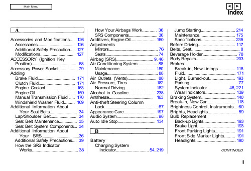
Accessories and Modifications.... 126Accessories................................. 126Additional Safety Precaution.... 127Modifications............................. 127ACCESSORY (Ignition KeyPosition)........................................ 68Accessory Power Socket................ 79AddingBrake Fluid................................. 171Clutch Fluid................................ 171Engine Coolant........................... 163Engine Oil................................... 159Manual Transmission Fluid ..... 170Windshield Washer Fluid......... 169Additional Information AboutYour Seat Belts........................ 34Lap/Shoulder Belt....................... 34Seat Belt Maintenance................ 35Seat Belt System Components... 34Additional Information AboutYour SRS...................................36Additional Safely Precautions.... 39How the SRS IndicatorWorks (38)How Your Airbags Work............ 36SRS Components......................... 36Additives, Engine Oil..................... 160AdjustmentsMirrors.......................................... 76Seats.............................................. 74Airbag (SRS)................................ 9, 46Air Conditioning System................. 88Maintenance............................... 180Usage............................................. 88Air Outlets (Vents).......................... 88Air Pressure, Tires........................ 182Normal Driving.......................... 182Alcohol in Gasoline........................ 238Antifreeze....................................... 163Anti-theft Steering ColumnLock............................................... 67Appearance Care........................... 197Audio System................................... 96Auto Idle Stop (134)BatteryCharging SystemIndicator............................ 54, 219Jump Starting............................. 214Maintenance............................... 175Specifications............................. 235Before Driving............................... 117Belts, Seat........................................... 8Beverage Holder.............................. 78Body Repairs.................................. 203BrakesBreak-in, New Linings .............. 118Fluid............................................ 171Light, Burned-out...................... 193Parking.......................................... 77System Indicator.................. 46, 221Wear Indicators......................... 139Braking System.............................. 140Break-in, New Car......................... 118Brightness Control, Instruments... 60Brights, Headlights......................... 59Bulb ReplacementBack-up Lights........................... 193Brake Light................................ 193Front Parking Lights................. 191Front Side Marker Lights......... 191Headlights. (190)CONTINUEDIndexBulb ReplacementInterior Light.............................. 195License Plate Lights.................. 194Specifications............................. 235Turn Signal Lights..................... 191Bulbs, Halogen. (196)Cables, Jump Starting With.......... 214Capacities Chart............................. 234Carbon Monoxide Hazard.............. 40Carrying Cargo.............................. 128Cassette PlayerCare............................................. 116Operation.................................... 102CAUTION, Explanation of............... ii CD Changer.................................... 112CD Player........................................ 106Certification Label......................... 232Chains............................................. 187Charge/Assist Gauge..................... 55Change OilHow to......................................... 161When to....................................... 150Changing a Flat Tire (185)Changing Engine Coolant............. 165Charging System Indicator.... 54, 219CheckingBattery Condition...................... 175Brake Fluid................................. 171Clutch Fluid................................ 171Drive Belts.................................. 181Engine Coolant........................... 123Engine Oil................................... 122Fuses........................................... 222Manual Transmission Fluid..... 170Checklist, Before Driving............. 117Child Safety...................................... 19Cleaner Element, Air..................... 173CleaningExterior....................................... 198Interior........................................ 201Seat Belts.................................... 201Vinyl............................................ 201Windows..................................... 202Clock, Setting the.......................... 101Clutch Fluid.................................... 171CO in the Exhaust......................... 240Cold Weather, Starting in............. 133Compact Spare............................... 206Consumer Information*. (244)Controls, Instruments and.............. 58CoolantAdding......................................... 163Checking..................................... 123Proper Solution.......................... 163Replacing.................................... 165Temperature Gauge.................... 56Corrosion Protection..................... 202Crankcase Emissions ControlSystem......................................... 240Current Fuel Mileage...................... 53Customer Relations Office.. (244)DANGER, Explanation of................. ii Dashboard.................................... 2, 44Daytime Running Lights................. 60Dead Battery, What to Do............ 214Defects, Reporting Safety............. 248Defog and Defrost........................... 82Defogger, Rear Window................. 63Defrosting the Windows................. 82Dimensions..................................... 234Dimming the Headlights................59IndexDipstickEngine Oil................................... 122Directional Signals........................... 61Disabled, Towing Your Car If...... 228Disc Brake Wear Indicators......... 139Disposal of Used Oil...................... 162Display Change Button................... 49DoorsLocking and Unlocking............... 69DOT Tire Quality Grading........... 236Downshifting, 5-speed ManualTransmission.............................. 136Drive Belts...................................... 181Driver and Passenger Safety............ 5Driving............................................ 131Economy..................................... 124In Bad Weather.......................... 142In Foreign Countries.. (239)Economy, Fuel............................... 124Emergencies on the Road............. 205Battery, Jump Starting.............. 214Brake System Indicator............ 221Changing a Flat Tire.. (207)Charging System Indicator...... 219Checking the Fuses................... 223Low Oil Pressure Indicator...... 218Malfunction Indicator Lamp.... 220Overheated Engine................... 217Emergency Brake............................ 77Emergency Flashers....................... 63Emergency Towing....................... 228Emissions Controls........................ 240EngineBelts............................................. 181Coolant Temperature Gauge ..... 56Malfunction IndicatorLamp................................. 47, 220Oil, What Kind to Use............... 159Overheating................................ 217Specifications............................. 234Engine Speed Limiter.................... 137Ethanolin Gasoline....................... 238Evaporative Emissions Controls.. 240Exhaust Fumes................................ 40Expectant Mothers, Use of SeatBelts by......................................... 17Exterior, Cleaning the. (198)Fabric, Cleaning............................. 201Fan, Interior...................................... 82Features, Comfort andConvenience................................. 81Filling the Fuel Tank..................... 119FilterAir Conditioning........................ 181Oil................................................ 1615-speed Manual TransmissionChecking Fluid Level................ 170Shifting the................................. 136Flashers, Hazard Warning.............. 63Flat Tire, Changing a.................... 185FluidsBrake........................................... 171Clutch.......................................... 171Manual Transmission............... 170Windshield Washer................... 169FM Stereo RadioReception.................................... 110Foreign Countries, Driving in...... 239Four-way Flashers (63)CONTINUEDIndexFront End, Towing byEmergency Wrecker................. 228Fuel.................................................. 118Fill Door and Cap....................... 119Gauge............................................ 56Octane Requirement................. 118Oxygenated................................ 238Reserve Indicator......................... 56Tank, Filling the......................... 119Fuses, Checking the. (223)Gas Mileage, Improving................ 124Gasohol........................................... 238Gasoline.......................................... 118Fuel Reserve Indicator................ 47Gauge............................................ 49Octane Requirement................. 118Tank, Filling the......................... 119Gas Station Procedures................. 119GaugesEngine CoolantTemperature............................ 56Fuel (56)Gearshift Lever Positions 5-speed ManualTransmission.......................... 136Glass Cleaning.............................. 202Glove Box.. (78)Halogen Headlight Bulbs.............. 190HatchOpening the.................................. 69Open Monitor Light.................... 47Hazard Warning Flashers............... 63HeadlightsDaytime Running Lights............. 60High Beam Indicator................... 47High Beams, Turning on............ 59Low Beams, Turning on ............. 59Reminder Beeper......................... 59Replacing Halogen Bulbs......... 190Turning on.................................... 61Heating.............................................. 81High Altitude, Starting at.............. 133High-Low Beam Switch .................. 59Hood Latch..................................... 174Hood, Opening the (120)Horn..................................................... 3Hot Coolant, Warning about........ 163Hydraulic Clutch............................ 171Hydroplaning. (142)Identification Number, Vehicle.... 232If Your Car Has to be Towed....... 228IgnitionKeys............................................... 65Switch............................................ 67Timing Control System............. 241Important Safety Precautions .......... 6Indicator Lights, InstrumentPanel.............................................. 45Inflation, Proper Tire .................... 182Normal Driving.......................... 183Inside Mirror.................................... 74Inspection, Tire.............................. 184Instrument Panel............................. 45Instrument Panel Brightness......... 60Interior Cleaning............................ 201Interior Light.................................... 80Introduction.........................................i。
现代汽车自动变速箱维修技术

输入
RVS Clutch
UD Clutch
现代汽车
15
自动变速箱维修技术
HIVEC自动变速箱结构、特点
2ND
RVS OD
LR
UD
现代汽车
16
自动变速箱维修技术
HIVEC自动变速箱结构、特点
输出行星支架 前排行星齿轮
后排行星齿轮 OD行星支架
现代汽车
17
自动变速箱维修技术
HIVEC自动变速箱结构、特点
阀体总成(下半部)
Fail safe v/v B
T/Convertor 阀
Fail safe v/v A
现代汽车
Regulator valve 32
DCC 控制阀
自动变速箱维修技术
HIVEC自动变速箱结构、特点
阀体总成(下半部)
L/R转换阀球
现代汽车
UD 钢球 及 弹簧
OD 钢球 及 弹簧
33
自动变速箱维修技术
Switch V/V
自动变速箱维修技术
电磁阀
HIVEC自动变速箱结构、特点
现代汽车
30
自动变速箱维修技术
HIVEC自动变速箱结构、特点
阀体总成(下半部)
倒挡单向阀球及弹簧 REVERSE CHECK BALL
L/R降压阀及 主油压阀球、弹簧
现代汽车
31
自动变速箱维修技术
HIVEC自动变速箱结构、特点
现代汽车
4
自动变速箱维修技术
HIVEC自动变速箱——主要特点
项目
采用OWC
内
容
1.OWC采用(改善1-2 档换档冲击现象) 2.控制原理:升2挡之前先解除 LR压力(NO 200rpm附近)
韩国现代Hyundai电机安装维护手册

Installation and maintenance forPolyphase AC Induction MotorsAll operations serving transport, installation, connection,operation and maintenance by skilled, qualified and responsible personnel ensures safe and proper use of motors.Read instructions carefully before attempting to install, operateor service motors and retain for future reference and work with care. Especially, safety precautions must be observed to protect personnel from possible injury which will be caused by high voltage, hot surface and rotating parts.RECEIVING1. Check motor & nameplate data (HP, Pole, Voltage and etc.).2. Check any damage or loose parts during transportation and stopcommissioning if necessary.3. Turn shaft by hand to check smooth rotation.4. If shaft is clamped by locking device to prevent axial movement of heavy rotor duringtransportation, please remove it to run motors and retain it for future transport.WARNING1. High voltage, hot surfaces and rotating parts of electrical machinery can cause seriousor fatal personal injury and damage to property. Qualified personnel should performproper installation, operation and maintenance. Recommendations to be familiarizedare NEMA MG2, the National Electric Code, IEC364(prEN50110-1) and all sound local safety practices.2. Before attempting maintenance or repair, avoid contact with energized circuits anddisconnect and de-energize all power sources to the motor and to the necessarydevices to avoid electrical shock.3. Before motor is energized, avoid contact with rotating parts and ensure that shaft key is fully captive or removed.4. When working near machinery with high noise levels, suitable protection must be used.5. Automatic-reset thermal protection should not be used where unexpected automaticstarting will be hazardous to personnel.6. Proper safeguards or protective devices against possible failure of motor-mountedbrake, especially on overhauling load applications should be provided and should not be by-passed. And a suitable enclosure should be provided against access tothe motor or other un-authorized personnel.7. Grounding of motor against fatal injury to personnel should be in accordance with theNational Electrical Code and applicable local practice. Grounding cable and terminalshould be securely crimped with proper crimping tools for safe grounding.8. Repair of Explosion-proof motors should be made by Hyundai, U/L,CSA or other listedauthorized service center to maintain those listings, safety and special feature inhazardous area. The use of non-explosion-proof motors in hazardous areais prohibited unless they are expressly intended for such use.STORAGE1. When storing motors without immediate installation, to keep motors in best condition,make sure of dry, clean, dust-free and low-vibration environment to avoid danger ofbearing damage at rest.2. Precautions should be taken to prevent the entrance of moisture, dust or dirt duringstorage especially for winding and bearing.3. Before commissioning, make sure insulation resistance of winding. In case of resistancevalues¡1§, the windings should be dried.LOCATION1. Drip-proof motors (IEC protection degree IP23) are intended for use in well ventilatedareas where the atmosphere is reasonably free of dirt, moisture and corrosion andnot intended for use in outdoor.2. Enclosed motors (IEC protection degree IP44) are intended for operation wherethey are exposed to dirt, moisture, dust and most outdoor conditions.3. Explosion-proof motors are designed for operation in hazardous areas classified byUnderwriters' Laboratories, National Electrical Code, Canadian Standard Association and IEC79.4. Chemical heavy duty enclosed motors are designed for use in highly corrosive orexcessively moisture locations.5. Standard ambient condition of motors are rated for ambient temperatures of -20¡+40¡ (-40¡with low temperature grease such as Beacon325) and altitudes below1000m(3300feet) above sea level.MOUNTING1. Mount motors securely on a firm and flat base and make sure of solid foot or flangesolid foot or flange mounting. All ball bearing normal thrust motors can be side wall orcan be side wall or ceiling mounted and can be vertically mounted for motors up to and including 326frame(IEC200L) size. For the recommendations of other applications,check nearest Hyundai office or sales agents.2. Align motors accurately using flexible coupling for direct drive if possible. Because thebalance of motors is made by half-key, the coupling or pulley must be half-key balanced.Mount or remove belt pulley or coupling only using appropriate means and cover them with a safety guard and avoid excessive belt tensions. Consult drive or equipmentmanufacturer or Hyundai for drive recommendations.3. The bolts for motor mounting and base assembly must be carefully tightened to prevent change in alignment and possible damage to the equipment applying the recommended tightening torques shown in table. Use the recommended torques for medium carbonsteel bolts identified by three radial lines at 120 degrees on the head and use 50% ofthe recommended torques for low carbon steel bolts with no ID marks. In case of motors with 8 holes in feet, these 8 holes are used for the application of dual frame sizes.Only 4 holes are used for mounting in accordance with outline drawing.Bolt Size RecommendedTorqueInch Metric Ft.-lb.N-M1/4M67-119-155/16M814-2119-283/8M1025-3734-501/2M1260-9081-1225/8M16120-180163-2443/4M20210-320285-4334. If bases are removed from enclosed motors having bolt-on base,the enclosure must be maintained by plugging or closing the boltholes and do not replace the base bolts in the frame with the baseremoved.5. In case of enclosed motors having drain plugs, remove them fromthe end shields or frame in the bottom side for the use in outdoors or in other high moisture area.6. Because low voltage motors per IEC are components for installation6. Because low voltage motors per IEC are components for installationin machinery as defined in Machinery Directive89/392/EEC, commissioning is prohibited until conformity of the end product with this directive has been established per EN60204-1 for European country.7. The application of pulleys, sheaves, sprockets and gears on motor shaft isdescribed in NEMA standard MG1-14.07. The application of V-belt sheave dimensions to AC motors is shown in NEMA MG1-14.41.The V-belt sheave diameters should not be less than the values in Tablebelow and the sheave width should not be wider than the maximum widthper equation below.Maximum sheave width = 2(N-W) – 1/4”Maximum sheave width = (N-W)# N-W (E for IEC) = the usable shaft lengthSheave ratios greater than 5:1 & center to center distances less than the diameter of large sheave should be referred to Hyundai.8. Make necessary ventilation passage for the best operation of motors. In case of beltpulley, ventilation opening of rim of pulley is essential for motors.The ventilation must not be obstructed. The distance between ventilation openings of motors and wall or obstacle should be maintained by minimum 25mm(1inch) andventilation diameter divided by 4. Motors with shaft ends pointing upward are to beprovided with a cover by the customer to prevent foreign materials from falling intothe ventilation or openings.POWER SUPPLY and CONNECTIONS1. Wiring of motor, control, grounding and overload protection should be in accordancewith the National Electric Code and all sound local building codes or practices only by qualified technical personnel.2. Power supply should agree with nameplate voltage and frequency and permissiblevariations of power supply are ±5% for frequency, ±10% for line voltage and ±10% for combined variation to avoid elevated temperatures and effects on the electromagnetic compatibility. (IEC motors :±2% for frequency, ±5% for line voltage per IEC34-1,EN60034-1 for multi-voltage motors)3. Thermally-protected motors to prevent excessive temperature rise or overload havetwo terminals of protectors (P1,P2) and should be connected to the control panel according to the connection diagram inside of the conduit box.Manual-reset protectors can be reset after motor cooled by pressing reset button and Automatic-reset protectors(no external button) reset automatically after motor cooled.Do not use Automatic-reset protectors where unexpectedautomatic starting will be dangerous to personnel.4. Dual voltage motors can be connected for the desired voltage using the connectiondiagram inside of the conduit box.5. Minimum clearances between un-insulated live parts and between such parts and earth must not be below 8mm at Volts¡550V,10mm at Volts¡725V, 14mm at Volts¡1000V.Because no presence of foreign objects, dirt or moisture is admitted in the conduit box, close unused cable entrance holes and the box itself in a dust- and watertight manner.6. For motors with brakes, check satisfactory functioning of brake before commissioning.7. Standard connection diagrams for three phase motors without any accessories areshown as below and rotation can be changed by interchanging any two line leads.Use appropriate cable terminals with proper crimping tools and protective andpermanent conductor connection without loose wire ends is important for safety.(1) 3 Leads, Single voltage(2) 6 Leads, Dual voltage & voltage ratio 1 to 3, Single voltage1) Direct-on-line Start & Run2) Wye Start & Delta Run(Low voltage only)3) Control for Wye Start & Delta Run (Low voltage only)(3) 9 Leads, Dual voltage & voltage ratio 1 to 2, Wye interconnection 1) Direct-on-line Start & Run2) Control for Wye Start & Delta Run(Low voltage only)(4) 12 Leads, Dual voltage, Delta interconnection1) Direct-on-line Start & Run2) Wye Start & Delta Run(Low voltage only)3) Control for Wye Start & Delta Run (Low voltage)4) Control for Wye Start & Delta Run (High voltage)5) Part winding start (Low vlotage only)* For part winding start with magnetic contactor, M2 contactor should be closed within two seconds after M1 contactor is closed.* Part winding start at low voltage is satisfactory only for 4pole and above.( 4p, 6p, 8p and above )OPERATION1. If the motor has been stored for an extensive period or in a damp location, check the insulation resistance of stator winding & bearings.If the resistance of stator winding is lower than 1Mega Ω, dry out motors thoroughly with maximum drying temperature of 85¡(185¢) in one of the following ways.1) Dry the stator in an oven until the insulation resistance is constant for a one-half hourperiod.2) Enclosure the motor with a canvas or similar covering leaving a opening at the top formoisture to escape. Insert heaters or lamps with care to avoid localized damage dueto too closer heating to the winding and leave them until the insulation resistance is constant for a one-half hour period.3) With the rotor locked, apply approximately 10% of rated voltage and increase currentgradually through the windings until temperature measured with thermometer reaches 85¡(185¢; Do not exceed this limit). Maintain 85¡until the insulation resistance is constant for a one-half hour period.Turn the shaft by hand to check the bearing and it may be necessary to re-grease orchange rusted bearings depending on the period and condition of storage.2. Operate motor at no load (disconnected load) and check rotation (without key ifuncoupled) for free running. Interchange any two leads to change direction of rotationfor three phase motor.3. Connect load and operate for an initial period of at least one hour to check any unusualnoise, vibration or hot spots and check those items periodically even after successfulstart-up. Acceptable vibration severities can be decided by NEMA MG1-7 (2¡6pole:0.15, 8pole:0.12in/sec peak) and IEC34-14 (H¡132:1.8,132£H¡225:1.8(4pole and larger) & 2.8(2pole), H¡225:2.8(4pole and larger) & 4.5(2pole) in mm/sec rms.) for no load and uncoupled condition.4. Check operating current against nameplate current. Be careful not to exceed the valueof nameplate amperes multiplied by the service factor under continuous load.5. When 208-230/460V motors with alternate voltage of 200V at 1.0 SF are used on 200V,the sip of motors will increase approximately 30% and torques will be reduced byapproximately by 20 to 30%. Therefore, user should check and determine that motors will start and accelerate without injurious heating and with adequate torque.MAINTENANCE1. INSPECT motor regularly and keep motor clean and dry. In case of heavy dirt ordeposits, clean air channels periodically.2. If the period of storage or stop of running of motor is more than one month, turn theshaft by hand to check the smooth rotation of bearings every one month and check the insulation resistance of winding every three months as minimum.3. Special features of Explosion-proof motors should be maintained in accordance with U/L, CSA or other authorized standard in hazardous area.Therefore, repair of Explosion-proof motors is recommended to be made by Hyundai, U/L, CSA or other listed authorized service centers to maintain those listings,safety and special features.4. In order to clean stator windings, use a soft brush and a slow acting solvent(if necessary) without affecting on coils, insulation and varnish in a well ventilated room for safety.LUBRICATION for maintenance1. Double shield and pre-lubricated ball bearing motors without grease fittings are adequately greased for life at the factory and do not need re-lubrication.2. Motors with re-greasing facilities are shipped with grease for initial running and should be checked and re-lubricated periodically depending on the type of service (see below table) to maintain maximum bearing life.Do not lubricate excessively or too frequently to avoid damage of bearing and leakageof grease.Interval of Re-lubrication (Months) No. BRG. No.Amount of Initial ChargeAmount of Re-lubrication2P 4P 6P 8P 1 6205 14 g 9 g 4 6 6 6 2 6206 15 g 10 g 4 6 6 6 3 6208 30 g 15 g 4 6 6 6 4 6211 80 g 25 g 4 6 6 6 5 6213 80 g 14 g 3 6 6 6 6 6307 30 g 15 g 4 6 6 6 7 6309 60 g 20 g 4 6 6 6 8 6310 80 g 25 g 4 6 6 6 9 6311 100 g 30 g 4 6 6 6 10 6312 100 g 30 g 4 6 6 6 11 6313 100 g 23 g 3 6 6 6 12 6314 150 g 26 g 2 6 6 6 13 6316 180 g 33 g - 6 6 6 14 6318 240 g 41 g - 6 6 6 15 6320 300 g 41 g - 6 6 6 16 NU318 350 g 45 g - 3 6 6 17NU320400 g45 g-3663. For re-lubrication, clean the grease nipple and press in the exact amount of grease as in the table above by using the grease gun. Take a note that re-lubrication should be carried out while motor is operating. After re-lubrication, the bearing temperature willrise but, it will drop back to the normal value when the grease has reached its normal service viscosity.4. As long as lubrication is carried out in accordance with the table above, bearing willshow no problem with its operation even in the case that re-lubricated grease is notobserved at the drain plug, because the old grease is accommodated in the chamberof bearing housing. Remove the old grease when overhauling the machines.5. In case of initial or replacement charge, put a third of the grease amount of initial chargein the bearing and the rest amount of grease in the chamber of bearing housing.6. In case of lubrication for TEFC motors, remove the plastic caps on the fan coverfor access to the grease fittings.SERVICE1. Hyundai motors should be serviced by qualified personnel using proper tools,equipment and genuine Hyundai renewal parts.For further information, please contact nearest sales office of Hyundai heavy industries or sales agent.2. When ordering spares or renewal parts, please specify information on the nameplatesuch as model No., serial No., HP(or kW), frame size and pole.。
- 1、下载文档前请自行甄别文档内容的完整性,平台不提供额外的编辑、内容补充、找答案等附加服务。
- 2、"仅部分预览"的文档,不可在线预览部分如存在完整性等问题,可反馈申请退款(可完整预览的文档不适用该条件!)。
- 3、如文档侵犯您的权益,请联系客服反馈,我们会尽快为您处理(人工客服工作时间:9:00-18:30)。
Q 4.381
4th. Vehicle
5th. 6th. T/Con Spare Remarks
A
SLC
A
SLC
X-3 1.5 DOHC C
X-3 1.5 SOHC
B X-3 1.3 SOHC
RD 1.5 SOHC E
RD 1.5 DOHC
SEDAN
F RD 1.5 DOHC
WAGON
1st. Digit A/T Type G A4AF1
K A4AF2
2nd. M/Year
J : 1988 K : 1989 L : 1990 M : 1991 N : 1992 P : 1993 R : 1994 S : 1995
3rd. F/Gear ratio P 4.029 Erect Y 4.310 Erect L 3.656
Identification number is stamped as 2 rows of 6 digits each as below on the transaxle case. Identification number ☞
☜ Product Serial No.
1. Identification No. for α, β Series
KM176-5 KM175-5 KM175-6 F4A33 A4AF1 A4BF1
2500?00 2.17
3 elements with damper clutch
←
←
2200-2500 2500?00
←
←
2.02Βιβλιοθήκη 1.90Electronically controlled full-automatic
Chonan TSTC
GENERAL SPECIFICATIONS
6
Items Torque converter
Type Engine stall speed Stall torque ratio Transaxle type Speed Gear ratio 1st 2nd 3rd 4th Reverse Final gear ratio
- KM(Kyoto Model) - Alpha, Beta series
Application vehicle : SLC, Santamo J-1, Y-2,3 X-2,3 RD (Before 2000MY)
Chonan TSTC
MODEL LINE UP & T/A ID. NUMBER 2
4th. Vehicle
5th. 6th. T/Con Spare Remarks
T : 1996 N 3.977 Slant A RD 1.6 DOHC
V : 1997 L 3.659 Slant B RD 1.8 DOHC
W : 1998 X : 1999
3.443
Y : 2000 A 3.659 Slant C RD 2.0 DOHC
W : 1998 X : 1999
A Y-2 2.0 MFI
D
Y : 2000 B 4.007 Erect
1 : 2001
B Y-2 1.8 MFI
D
C 4.350 Erect A L-1 2.0 MFI
D
Chonan TSTC
MODEL LINE UP & T/A ID. NUMBER 5
2. Identification No. for KM Series
*2
A 3.705 Erect A Y-3 3.0 MFI
Non L/UP
B 3.900 Erect A L-1 3.0 MFI
Non L/UP
A 3.958 Erect A Y-3 3.0 SOHC D
Notation : - “D” in 5th. Digit ; Damper spring - *1 ; Domestic or export (except NAS) - *2 ;NAS - T/Con ; Torque converter
A X-2 1.5 FBC D
L : 1990 M : 1991 F 4.062 Slant B J-1 1.6 DOHC D
N : 1992 P : 1993
C
J-1 1.5
D
R : 1994 S : 1995
A SLC 1.5
D
T : 1996 G 4.367 Slant
V : 1997
B J-1 1.6 DOHC D
B KM176-5
C KM175-5
2nd. M/Year
3rd. F/Gear ratio
4th. Vehicle
5th. 6th. T/Con Spare Remarks
A 3.600 Erect A X-1 1.5 FBC
E 3.600 Slant A X-2 1.5 FBC D
J : 1988 K : 1989
G RD 1.5 DOHC
COUPE
Chonan TSTC
MODEL LINE UP & T/A ID. NUMBER 3
1. Identification No. for α, β Series
1st. Digit A/T Type
L A4BF1
2nd. M/Year
3rd. F/Gear ratio
1 : 2001
3.977
Notation : - T/Con ; Torque converter
Chonan TSTC
MODEL LINE UP & T/A ID. NUMBER 4
2. Identification No. for KM Series
1st. Digit A/T Type A KM171-5
1st. Digit A/T Type C KM175-5
D KM175-6
E KM177-8 H F4A33
2nd. M/Year
3rd. F/Gear ratio
4th. Vehicle
5th. 6th. Remarks T/Con Spare
A Y-2 2.0 DOHC D
F 4.007 Slant B Y-3 1.8 MFI
D
C Y-2 2.0 MFI D
D Y-3 1.8 DOHC D
G 4.350 Slant A J-1 1.8 DOHC D
B 4.007 Erect A Y-2 2.4 MFI B L-1 2.4 MFI
E 4.007 Slant A Y-3 2.0 DOHC D
*1
B H 2.0 DOHC D
F 4.350 Slant A Y-3 2.0 DOHC D