炸薯条炸鸡翅电炉小型油炸机价格
开店设备预算清单

避风塘饮品开业设备
饮品必备设备:
沙冰机(一般的300多,品牌的1300多)
封口机(手动和全自动)手动大概200多全自动1000多
冰箱(可以买冰柜也可以买成铁皮柜那种)
饮水机(主要是水源,有上下水最好用电热水器和净水器,大概4000 保证水源的一直使用,而且饮品调出来味道更好)
制冰机(主要指夏季,用冰量比较大,需要用制冰机提供冰块,东贝品牌,四千)
饮品选用设备:
搅拌机(也叫奶昔机,主要功能是搅拌,可用于饮品和小吃)
果汁机(东贝品牌,大概两千多)
冰淇淋机(东贝品牌,大概六千多)
小吃设备:
烤肠机(做烤肠的)大概300多
关东煮(做关东煮的)大概400多
松饼机(做松饼)大概100多
烤箱(做蛋挞)400
电热扒炉(做手抓饼,炒饭,炒面等都可以做)大概400多
无烟烤炉(无烟的,对房子不会有损毁)(烤翅,烤串)大概900多
章鱼炉(章鱼小丸子)大概600多
电炸锅(单缸的200多,双缸的400多,做油炸系列)
小吃类的上什么小吃就用什么设备,机器都是几百元。
节油炸炉(OCF30) 电炸炉系列 安装与操作手册说明书
作为商业食品设备服务协会(Commercial Food Equipment Service Association)会员,08/2022*8197348*注意在保修期内,如果客户在此FRYMASTER DEAN 公司设备中使用了非直接从FRYMASTER DEAN或者其授权服务中心购买的新零件或者返修件,会损坏设备原始设计,本保修将无效.此外,对于直接或者间接,全部或者部分由于安装任何改造零部件或未经授权的服务商提供的零部件而产生的任何损坏而顾客索赔或者相关费用,FRYMASTER DEAN 及其附属机构概不负责.注意本设备仅供专业从员使用,并只能由合格人员进行操作。
应由FRYMASTER DEAN厂家授权服务中心(FAS)或其他合格的专业人员执行安装、保养和修理。
由无资格人员执行安装、保养或修理可能导致制造商的保修无效。
有关合格人员的定义,请参阅本手册第1章。
注意本设备的安装必须符合设备安装所在国家和/或地区的国家和当地法规。
更多详情,请参阅本手册第2章中的“国家法规要求”。
美国顾客注意事项本设备的安装需符合国际职业建筑人员与法规管理人员联合会(BOCA)的基本给排水规范以及美国食品与药物管理局的《食品服务卫生手册》。
注意本手册中使用的图画和照片是用于说明操作、清洁和技术程序,可能与现场管理操作程序不符。
防止雷击等瞬间高压对设备的冲击。
节油炸炉(OCF30)™电炸炉系列安装与操作手册目錄第1章: 简介1.1 概述.......................................................................................................................................... 1-11.2 安全信息.................................................................................................................................. 1-11.3 计算机信息.............................................................................................................................. 1-21.4 欧共体(CE)特定信息......................................................................................................... 1-21.5 安装、操作和维修人员.......................................................................................................... 1-21.6 定义.......................................................................................................................................... 1-21.7 装运损坏索赔程序.................................................................................................................. 1-31.8 服務信息.................................................................................................................................. 1-3 第2章: 安装说明2.1 安装要求概述.......................................................................................................................... 2-12.1.1 清洁和通风.................................................................................................................. 2-22.1.2 电气接地要求.............................................................................................................. 2-22.1.3 澳大利亚要求.............................................................................................................. 2-32.2 电源要求.................................................................................................................................. 2-32.3 炸炉的安装位置...................................................................................................................... 2-42.4 安装JIB 支承架 ....................................................................................................................... 2-4 第3章: 操作说明3.1 设备设置及关闭程序.............................................................................................................. 3-23.2 操作.......................................................................................................................................... 3-23.3 可选配置上部自动补油系统.................................................................................................. 3-33.3.1 安装桶装油.................................................................................................................. 3-33.3.2 日常更换储油桶.......................................................................................................... 3-33.3.3 散装油补油系统.......................................................................................................... 3-4 第4章: 过滤说明4.1 准备好内置过滤系统以便使用.............................................................................................. 4-14.1.1 内置滤油系统的过滤纸或过滤垫准备....................................................................... 4-14.1.2 Magnasol过滤器组件的使用准备............................................................................... 4-24.2 过滤.......................................................................................................................................... 4-34.2.1 过滤器的操作............................................................................................................... 4-34.3 Magnasol过滤器的拆卸和重新组装....................................................................................... 4-54.4 排放和处理废油....................................................................................................................... 4-6 第 5章: 预防性保养5.1 清洁炸炉.................................................................................................................................. 5-15.2 每天检查和维护...................................................................................................................... 5-1iv5.2.1 检查炸炉和附件有无损坏-第天 .............................................................................. 5-15.2.2 清洁炉柜内外部-每天 .............................................................................................. 5-15.2.3 清洁内置过滤系统-每天 .......................................................................................... 5-15.3 每周检查和维修 ..................................................................................................................... 5-25.3.1 清洁炸锅和发热元件-每周 ...................................................................................... 5-25.3.2 将炸锅煮沸 .................................................................................................................. 5-25.3.3 清洁可拆卸零部件和附件-每周 .............................................................................. 5-35.4 每月检查和维修 ..................................................................................................................... 5-35.4.1 清洁可拆卸零部件和附件-每周 .............................................................................. 5-35.5 年度/定期系统检查 ................................................................................................................ 5-35.5.1 炸炉 .............................................................................................................................. 5-35.5.2 内置过滤系统 .............................................................................................................. 5-4 第6章: 操作员故障排除6.1 简介 ......................................................................................................................................... 6-16.2 故障排除 ................................................................................................................................. 6-26.2.1 控制器和加热问题 ...................................................................................................... 6-26.2.2 错误信息和问题显示 .................................................................................................. 6-26.2.3 提篮问题 ...................................................................................................................... 6-36.2.4 过滤问题 ...................................................................................................................... 6-46.2.5 自动补油系统问题 ...................................................................................................... 6-46.2.6 错误日志代码 (仅限于 3000控制器) .......................................................................... 6-5接線圖請參閱8197224 OCF電氣接線圖手冊附录 A: JIB 使用固态油的准备附录 B: 固态油融油器应用附录C: 散装油补油系统指引vOCF30™系列电炸炉第1章: 简介1.1 概述尝试操作作设备前,请通读本手册中的说明,本手册介绍了FPEL14、FPEL17型号的所有配置。
厨房设备报价
厨房设备报价项目背景厨房设备是餐饮行业的重要组成部分,其性能和质量直接关系到餐厅的运营效率和形象。
对于餐饮企业来说,选择合适的厨房设备是一个重要的决策。
在进行厨房设备采购的过程中,需要对各种设备进行详细的了解,并进行合理的报价比较,以选择最适合自己的设备。
本文将对常见的厨房设备进行分类,并给出各类设备的报价,旨在为餐饮企业提供参考和指导。
分类及报价1. 烤箱•电烤箱,报价:1000元-5000元电烤箱是餐厅厨房中常见的设备,适用于面包、蛋糕等烘烤食品的制作。
电烤箱通常有多层架,可同时烘烤多个食品。
报价范围在1000元至5000元之间,具体价格取决于烤箱的容量和品牌。
•燃气烤箱,报价:2000元-8000元燃气烤箱与电烤箱相比,具有更高的烘烤效率和更快的加热速度。
燃气烤箱通常配备有独立控制温度的燃烧器,可以根据不同食品的要求进行精确的控制。
报价范围在2000元至8000元之间,具体价格取决于燃气烤箱的容量和品牌。
2. 冷柜•冷藏柜,报价:3000元-8000元冷藏柜是餐厅厨房中储存食材和食品的重要设备。
冷藏柜通常具有可调温度控制和防霜功能,可以保持食材的新鲜度和质量。
报价范围在3000元至8000元之间,具体价格取决于冷藏柜的容量和品牌。
•冷冻柜,报价:4000元-10000元冷冻柜适用于储存需要长时间冷冻保存的食材和食品。
冷冻柜通常具有低温急冻功能和定时解冻功能,并具备自动控温和防霜功能。
报价范围在4000元至10000元之间,具体价格取决于冷冻柜的容量和品牌。
3. 炉灶•电磁炉,报价:600元-2000元电磁炉是一种节能、安全、环保的炉灶设备,适用于各类炒菜和煲汤。
电磁炉具有温度控制和定时功能,可以根据不同菜品的需求进行精确的调控。
报价范围在600元至2000元之间,具体价格取决于电磁炉的功率和品牌。
•燃气炉,报价:800元-3000元燃气炉是餐厅厨房中使用最为广泛的炉灶设备,适用于各类烹饪方式。
HD976X 电子油炸器操作手册说明书
HD976XManuale di istruzioni2INDICEImportante 3Introduzione 6Descrizione generale 6Primo utilizzo 8Predisposizione dell'apparecchio 8Posizionamento del fondo in rete e delriduttore di grassi 8Tabella dei cibi 9Modalità d'uso dell'apparecchio 12Frittura ad aria 12Passaggio a una funzione preimpostata diversadurante la cottura 16Utilizzo della modalità manuale 17Modifica della temperatura o del tempodi cottura in qualsiasi momento 18Scelta della modalità di mantenimento dellatemperatura 19Preparazione di patatine fritte fatte in casa 20Pulizia 21Conservazione 23Riciclaggio 23Garanzia e assistenza 23Risoluzione dei problemi 234ITALIANO-Collegare l'apparecchio esclusivamente a unapresa di messa a terra. Accertarsi sempre che laspina sia correttamente inserita nella presa dicorrente.-Posizionare e utilizzare sempre l'apparecchio suuna superficie piana, stabile e orizzontale.-Questo apparecchio non è stato progettatoper essere utilizzato in abbinamento a untimer esterno o a un sistema separato contelecomando a distanza.-Non collocare l'apparecchio contro una pareteo un altro apparecchio. Lasciare almeno 10 cmdi spazio libero sul retro e i lati e 10 cm di spaziosopra l'apparecchio. Non posizionare alcunoggetto sopra l'apparecchio.-Non usare l'apparecchio per scopi diversi daquelli descritti nel presente manuale.-Durante la frittura ad aria calda viene emessovapore attraverso le aperture di circolazionedell'aria. Tenere le mani e il viso a distanzadi sicurezza dal vapore e dalle aperture dicircolazione dell'aria. Fare attenzione al vaporee all'aria calda anche quando si rimuove ilrecipiente dall'apparecchio.-Le superfici accessibili potrebbero diventarecalde durante l'uso (fig. 1).-Il recipiente, il cestello e gli accessori all'internodi Airfryer si surriscaldano durante l'uso. Fareattenzione quando li si maneggia.-Al fine di garantire un funzionamento ottimale,accertarsi prima di ogni utilizzo del dispositivoche la resistenza e l'ambiente circostante sianopuliti e privi di residui di cibo.-Non posizionare l'apparecchio al di sopra o inprossimità di fornelli a gas o ogni tipo di fornelloo piastra di cottura elettrici, né all'interno di forniriscaldati.-Non inserire ingredienti dal peso ridotto o cartaforno nell'apparecchio.-Non toccate mai l'interno dell'apparecchiomentre è in funzione.-Non appoggiate l'apparecchio sopra o inprossimità di materiale combustibile, ad esempiotovaglie e tende.ITALIANO5 -Non lasciate mai incustodito l'apparecchio in funzione.-Scollegare subito l'apparecchio se daquest'ultimo fuoriesce del fumo scuro. Attendere che dall'apparecchio non fuoriesca più fumoprima di rimuovere il recipiente.Attenzione-Questo apparecchio è stato progettato per il normale uso domestico. Non è progettato perl'uso in ambienti quali zone dedicate alla cucina all'interno di negozi, uffici e altri ambienti dilavoro. Non è ideato per essere utilizzato dagliospiti di alberghi, motel, bed and breakfast e in altri ambienti residenziali.-Per eventuali controlli o riparazioni, rivolgersi sempre a un centro autorizzato Philips. Nontentare di riparare l'apparecchio da soli per non invalidare la garanzia.-Questo apparecchio deve essere utilizzato a una temperatura ambiente compresa tra 5°C e 40°C. -Scollegare sempre il cavo di alimentazione dopo l'uso.-Lasciare raffreddare l'apparecchio per circa 30 minuti prima di maneggiarlo o pulirlo.-Non riempire troppo il cestello. Riempire il cestello solo fino all'indicazione MAX.-Assicurarsi che gli ingredienti preparati con questo apparecchio siano di colore giallo-dorato e non scuri o marroni. Rimuovere i residui bruciati. Non friggere patate fresche a unatemperatura superiore a 180°C (per ridurre alminimo la produzione di acrilammide).-Fare attenzione quando si pulisce la zona superiore della camera di cottura: la resistenza ei bordi delle parti metalliche sono caldi.Campi elettromagnetici (EMF)Questo apparecchio Philips è conforme a tutti gli standard e alle norme relativi ai campi elettromagnetici. Spegnimento automaticoL'apparecchio dispone della funzione di spegnimento automatico. Trascorso il tempo impostato, l'apparecchiosi spegne automaticamente. Per spegnere l'apparecchio manualmente, ruotare il timer in posizione "0".6ITALIANOITALIANO78ITALIANOITALIANO910ITALIANOITALIANO2122ITALIANOITALIANO2324ITALIANOITALIANO25© 2021 Philips Domestic Appliances Holding B.V. All rights reserved。
AFD-280U 炸鸡机配件清单说明书
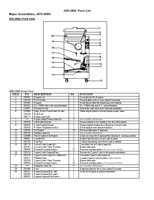
AFD-280U Side ViewITEM P/N DESCRIPTION NO. FUNCTION1 202881 Power Cord Inlet 1 Connector for Power Cord.2 203425202946202942202950 Inlet Power Cord, USA, JapanInlet Power Cord, EuropeanInlet Power Cord, Great BritainInlet Power Cord, Australia1 Provides electrical power from wall outlet. Plugs intopower cord inlet.2 202172202790202354 Hard-wired Power Cord, USA, JapanHard-wired Power Cord, EuropeanHard-wired Power Cord, Australia1 Provides electrical power form wall outlet. Hard-wired power cords.2 290311290308290312 Kit, Power Cord, USA, JapanKit, Power Cord, EuropeanKit, Power Cord, AustraliaPower cord kit that converts from power cord inlet tohard-wired power cords.For more information see replacement part proceduresat 3 202890202523202585202539202892 Back panelHandlesScrewsRetainer (Plastic)Nut (U-clip)12222Removable cover for internal access.Hand holds for Back PanelSecures the Back Panel to the machineHolds screws to Back PanelAttachment point for screws4 202518 Lift Cylinder Cap, Adjustable 1 Attaches to Lift Cylinder Shaft, contacts the Saddle.5 216595 Rear Caster 1 Allows Dispenser movement for cleaning.6 216596 Front Caster with brake. 1 Allows Dispenser movement, locks position.7 202513220497 Lift Cylinder CoverLift Cylinder Cover Nut11Lift Cylinder protective cover.Secures the Lift Cylinder Cover.8 202782 Lift Saddle Assembly 1 Carries baskets from the Upper to the Lower Guide.AFD-280U Rear ViewITEM P/N DESCRIPTION NO. FUNCTION1 202061202190202766202765 Air Compressor, Ramped Valve, 110V/60HzAir Compressor, Ramped Valve, 220V/50HzAir Compressor, Ramped Valve, 220V/60HzAir Compressor, Ramped Valve, 110V/50-60Hz1 Compressed air source for Dispenser operations.2 202878 Airline, 1/4" x 24" 24" Connects Compressor to Air Reservoir.3 202196 Compressor Control Switch 1 Controls Compressor, On at 40 psi, Off at 60 psi.4 202197 Pressure Relief Valve 1 Over pressure safety valve for Air Reservoir.5 202199202614 Air Inlet FilterFilter Media only11Filters air entering the Air Compressor.Replaceable filter media.6 202861Air Reservoir Assembly -- See assembly illustration7 202793 Power Supply, 24.5 VDC 1 Provides D.C. power for Dispenser operations.8 202900 Stopgate Assembly -- See assembly illustration9 202582 Manifold Assembly -- See assembly illustration10 ------ Upper Guide Support Assembly -- See assembly illustration11 202051 Air Regulator Assembly -- See assembly illustration12 216595 Rear Casters 2 Allows Dispenser movement for cleaning.13 290626290063 Plus Controller BoardE-prom11Controls Dispenser electrical functions.Programs the controller board.14 202038 Lower Guide Optical Sensor 1 Senses baskets exiting the Lift and when theLower Guide is full.15 202038 Lift Optical Sensor 1 Senses baskets in the Saddle when the Lift israised.16 202057 Accumulator Doors Air Cylinder 1 Pneumatic actuator for the Accumulator Doors.17 290685 Load Cell 1 Senses the weight of the fries.18 ----- Accumulator Door Carriage Assembly -- See assembly illustration19 ----- Drum Motor Assembly -- See assembly illustration20 202881 Power Cord Inlet 1 Connects the Dispenser to the wall outlet power.21 202062 Air Reservoir Mounting Straps 2 Secures Air Reservoir to chassis.AFD-280U Compressor AssemblyAFD-280U Compressor AssemblyITEM P/N DESCRIPTION NO. DETAILS1 202061202765202190202766 Air Compressor, 110 VAC, 60 HzAir Compressor, 100 VAC, 50-60 HzAir Compressor, 220 VAC, 50 HzAir Compressor, 220 VAC, 60 Hz1111Provides compressed air for Dispenser pneumatic system.2 202857 Bubble Shock Mount 4 Provides vibration isolation.3 202858 Socket head cap screw, 8-32 X 1/4” 8 Secures Shock Mounts to Dispenser chassis.4 213509213432 Socket head cap screw, 8-32 X 1/2”Lock Washer, #844Secures Shock Mount to CompressorLock washer for cap screw.5 215465 Push fitting, 1/4” tube - 1/4 NPT 1 Attaches 1/4” airline to the Air Compressor.6 202199219262 Air Filter Assembly with Filter MediaFilter Media only11Filters air entering the Air Compressor.Replaceable filter media.AFD-280U Air Reservoir AssemblyAFD-280U Air Reservoir AssemblyITEM P/N DESCRIPTION Number DETAILS--- 202861 Air Reservoir Assembly Stores Compressed Air for Dispenser Operations.1 202196 Pressure Control Switch Part of Air Reservoir AssemblySet for On at 40 psi (2.8 Bar) Off at 60 psi (4.1 Bar).2 215465 ¼” Push Tube Fitting Part of Air Reservoir Assembly3 202243 Check Valve Part of Air Reservoir Assembly4 291321 90° Elbow Part of Air Reservoir Assembly5 202197 Pressure Relief Valve Part of Air Reservoir Assembly6 291321 90° Elbow Part of Air Reservoir Assembly7 291324 Branch T Fitting Part of Air Reservoir Assembly8 ---- Pressure Tank Part of Air Reservoir Assembly9 213477 90°, ¼” Push Tube Fitting Part of Air Reservoir Assembly10 202062 Mounting Straps 2 Secures Air Reservoir to the chassis.AFD-280U Air Pressure Regulator AssemblyAFD-280U Air Pressure Regulator Assembly, p/n 202051ITEM P/N DESCRIPTION NO. DETAILS1 --- Pressure control knob. -- Pull up to unlock, turn to increase or decrease system pressure.Set for 30 psi. Part of Pressure Regulator Assembly2 213477 Airline fitting, 90° ¼” Push Tube 2 Airline Connection.3 --- Filter Bowl Cover Shield. -- Safety cover for the Filter Bowl. Part of Pressure Regulator Assembly.4 202604 Air Present Switch 1 Senses system operating pressure, adjusted for 20 psi On.5 202606 Air Pressure Gauge 1 Indicates regulator pressure setting.6 213372 Regulator Mounting Screws 2 Secures the regulator to the back panel.7 202480 Drain Line, 5/16” x 10” 10” Water drain line.---- 202051 Pressure Regulator Assembly 1 Complete Filter Regulator assembly.ITEM P/N DESCRIPTION NO. DETAILS1 202614 Filter Media Replacement Kit 1 Removes contaminants from system air pressure.2 --- Float Valve -- Part of Pressure Regulator Assembly.3 --- Drain Filter -- Part of Pressure Regulator Assembly.4 202245 Water Trap Bowl and Drain Fitting 1 Collects and drains moisture from system air pressure.--- 202051 Pressure Regulator Assembly 1 Complete Filter Regulator assembly.AFD-280U Manifold Assembly “Style A”AFD-280U Manifold Assembly “Style A”, p/n 202054 (replace with p/n 202582)ITEM P/N DESCRIPTION NO. DETAILS1 202582 Pneumatic Manifold Assembly 1 Distributes airflow to pneumatic cylinders.2 213318 Airline Fitting, 90°, 1/4” Push Tube 1 Airline connection.3 202572 Manifold Compressed Air Input 1 GREEN Airline from the Pressure Regulator.4 213318 Airline Fitting, 90°, 1/4” Push Tube 3 Airline connection.5 202479 Manifold Output, OPEN Stopgate 1 BLUE Airline to bottom Stopgate Cylinder fitting.6 202478 Manifold Output, CLOSE Stopgate 1 RED Airline to top Stopgate Cylinder fitting.7 202481 Manifold Output, OPEN Accumulator Doors 1 CLEAR airline to top Accumulator Cylinder fitting.8 202573 Manifold Output, CLOSE Accumulator Doors 1 YELLOW airline to bottom Accumulator Cylinderfitting.9 213320 Manifold Output, RAISE Lift Cylinder 1 OPAQUE airline to fitting at bottom of Lift Cylinder.10 203282 Airline Fitting, 1/4” OD-Barbed 2 Airline connection.11 213518 Allen Head Cap Screws, 10-32 X 1 1/2” 2 Secures Manifold Assembly to Mounting Bracket (23).12 203294 Airflow adjustment, Lift Cylinder DOWN 1 Controls the DOWN SPEED of the Lift Cylinder.13 202090 Airflow Adjustment, Stopgate OPEN “B” 1 Controls the OPENING SPEED of the StopgateCylinder.14 202090 Airflow Adjustment, Stopgate CLOSE “A” 1 Controls CLOSING SPEED of the Stopgate Cylinder.15 202090 Airflow Adjustment, Accumulator OPEN “B” 1 Controls the OPENING SPEED of the AccumulatorDoors.16 202090 Airflow Adjustment, Accumulator CLOSE “A” 1 Controls the CLOSING SPEED of the AccumulatorDoors.17 202021 Airflow Adjustment, Lift Cylinder UP speed 1 Controls the UP SPEED of the Lift Cylinder.18 219010 Manifold Solenoid & manual activator. 1 Switches the Stopgate airflow for OPEN & CLOSE.19 219010 Manifold Solenoid & manual activator. 1 Switches the Accumulator Doors airflow for OPEN &CLOSE.20 219009 Manifold Solenoid & manual activator. 1 Opens airflow to the Lift Cylinder to raise UP.Lift Cylinder DOWN is controlled by (12).21 215468 Electrical Connector, 8 position. 1 Connects Solenoid Wiring to the Controller BoardOutputs.22 202242 Manifold Vent 1 Exhausts manifold intermittent air pressures.23 ---- Manifold Mounting Bracket 1 Mounting for the Manifold Assembly24 213143213142 Allen Head Cap ScrewsStar Washers22Secures Mounting Bracket to Dispenser chassis.AFD-280U Manifold Assembly “Style B”AFD-280U Manifolds Assembly “Style B”, p/n 202582)ITEM P/N DESCRIPTION NO. DETAILS1 202582 Pneumatic Manifold Assembly 1 Distributes airflow to pneumatic cylinders.2 213318 Airline Fitting, 90°, 1/4” Push Tube 1 Airline connection.3 202572 Manifold Compressed Air Input 1 GREEN Airline from the Pressure Regulator.4 213369 Airline Fitting, Straight, 1/4” Push Tube 3 Airline connection.5 202479 Manifold Output, OPEN Stopgate 1 BLUE Airline to bottom Stopgate Cylinder fitting.6 202478 Manifold Output, CLOSE Stopgate 1 RED Airline to top Stopgate Cylinder fitting.7 202481 Manifold Output, OPEN Accumulator Doors 1 CLEAR airline to top Accumulator Cylinder fitting.8 202573 Manifold Output, CLOSE Accumulator Doors 1 YELLOW airline to bottom Accumulator Cylinderfitting.9 213320 Manifold Output, RAISE Lift Cylinder 1 OPAQUE airline to fitting at bottom of Lift Cylinder.10 203282 Airline Fitting, 1/4”-Barbed 2 Airline connection.11 213372 Allen Head Cap Screws, 10-32 X 2” 2 Secures Manifold Assembly to Mounting Bracket (23).12 203294 Airflow adjustment, Lift Cylinder DOWN 1 Controls the DOWN SPEED of the Lift Cylinder.13 202090 Airflow Adjustment, Stopgate C LOSE “A” 1 Controls CLOSING SPEED of the Stopgate Cylinder.14 202090 Airflow Adjustment, Stopgate OPEN “B” 1 Controls the OPENING SPEED of the StopgateCylinder.15 202090 Airflow Adjustment, Accumulator CLOSE “A” 1 Controls the CLOSING SPEED of the AccumulatorDoors.16 202090 Airflow Adjustment, Accumulator OPEN “B” 1 Controls the OPENING SPEED of the AccumulatorDoors.17 202021 Airflow Adjustment, Lift Cylinder UP speed 1 Controls the UP SPEED of the Lift Cylinder.18 219010 Manifold Solenoid & manual activator. 1 Switches the Stopgate airflow for OPEN & CLOSE.19 219010 Manifold Solenoid & manual activator. 1 Switches the Accumulator Doors airflow for OPEN &CLOSE.20 219009 Manifold Solenoid & manual activator. 1 Opens airflow to the Lift Cylinder to raise UP.Lift Cylinder DOWN is controlled by (12).21 215468 Electrical Connector, 8 position. 1 Connects Solenoid Wiring to the Controller BoardOutputs.22 202242 Manifold Vent 1 Exhausts manifold intermittent air pressures.AFD-280U Accumulator Doors / Load Cell AssemblyAccumulator Doors / Load Cell Assembly ITEM P/N DESCRIPTIONNo.DETAIL1 Slide RailAllows Accumulator Assembly Motion / Sensing 2 202068 Slide Rail Mount1 Attaches Accumulator Assembly to Slide Rail 3 203097 213142 Slide Rail Mounting Bolts Lock Washers 4 4 M6-1.0 x 16 Zinc Plated4 290685 213143 213142 Load Cell BoltsLock Washers1 2 2 Detects Weight of French Fries ¼-20 X ½” ¼” Zinc Plated5202908 213143 213142 Load Cell Mounting Bracket BoltsLock Washers1 2 2 Secures Load Cell to Chassis ¼-20 X ½” ¼” Zinc Plated6 202057 Accumulator Doors Cylinder 1 Pneumatically Operates the Accumulator Doors 7 203282 Straight Barbed Fitting1 1/8” NPT Barbed Airline Fitting 8203283 203290 90° Barbed Fitting Assembly: - 90° Elbow - Barbed Fitting 1 11/8” NPT to 10-32 UNC 90° Fitting 10-32 UNC Barbed Airline Fitting9 220464 Door Shaft Link 2 Actuator Linkage Connection Secured to the Door Shaft 10 202081 Hairpin Clip6 Secures Clevis Pins 11 202082 Clevis Pin, ¼ X 1” 6 Secures Linkages12 220463 Connector Link 4 Actuator Linkage Interconnection Link 13 220462 Center Link 1 Linkage attached to Pneumatic Cylinder 14 202974 202975 Flange Bearing Nylon Washer4 4 Bearing for Accumulator Door Shafts Flange Bearing Spacer15 202898 Machined Chassis Extrusion1 Machined Accumulator Chassis 16 220480 Accumulator Door Weldment, Left 1 Accumulator Door and Shaft17 213356 E-Clip2 Secures Accumulator Door Shaft within Accumulator Assembly not shown 220475 213356 Accumulator Door Weldment, Right E-Clip1 2 Accumulator Door and ShaftSecures Accumulator Door Shaft within Accumulator Assembly 18 220499 202214 Shaft Collar, 1 per shaftShaft Collar Set Screw, 8-32 X ½” 2 2 Protects inner Dispenser cabinet from contamination. Secures Shaft Collar to shaft. 19202901Cylinder Shaft Jam Nut, 5/8” X ½”1Locks Cylinder Shaft adjustment.AFD-280U Stopgate AssemblyStopgate AssemblyITEM P/N DESCRIPTION NO. DETAILS1 202902 Air Cylinder Assembly (Items 1 & 2) 1 Pneumatic actuator for the Stopgate.2 213318 ¼” Push Tube Fitting, 90° elbow 2 Airline connection.3 202901 Air Cylinder Jam Nut 1 Secures Air Cylinder to Chassis.4 202864 Machined Chassis Extrusion 1 Chassis machined from extrusion.5 202974202975 Flange BearingWasher22Bearing for Stopgate shaft.Spacer.6 203000 Air Cylinder Shaft End Block 1 Connects Air Cylinder to Stopgate Linkage.7 202082203092203093 Clevis PinCotter PinFlat Washer111Secures Linkage to End Block.8 203090 Stopgate Actuator Linkage 1 Linkage attached to Stopgate shaft.7 & 8 290676 Kit, Stopgate Linkage Stopgate linkage repair kit.9 202082202081 Clevis PinHairpin Clip11Secures Linkage to Stopgate shaft.10 202901 Cylinder Shaft Jam Nut, 1 Secures and adjusts Air Cylinder shaft to End Block.11 213145213142 Socket Head Cap Screw, ¼-20 X 5/8Lock Washer, ¼”22Secures Stopgate Chassis Assembly to the Dispenser panel.12 213356 E-Clip 2 Secures Stopgate shaft to assembly.13 220499202214 Shaft CollarShaft Collar Set Screw11Protect Dispenser inside from contaminants.Secure Shaft Collar to Shaft.14 220505 Stopgate Weldment 1 Stopgate welded assembly.AFD-280U Lift Cylinder AssemblyLift Cylinder AssemblyITEM PART NUMBER DESCRIPTION NO. DETAILS1 202194202516 Lift Cylinder Down SwitchSwitch Mounting Strap11Detects when the Lift Cylinder is down.Secures the Lift Switch2 202055202517213369 Lift CylinderJam Nut, ¾-16 UNCAirline Fitting, 1/8" NPT M X 1/4"OD111Pneumatic Actuator for the Lift SaddleSecures the Cylinder to the chassis.Airline connection.3 202194202516 Lift Cylinder Up SwitchSwitch Mounting Strap11Detects when the Lift Cylinder is up.Secures the Lift Switch4 202513 Lift Cylinder Shield 1 Protective cover for the Lift Cylinder.5 220497 Shield Nut 1 Secures the Lift Cylinder Shield.6 202518 Lift Cylinder Cap 1 Attaches to Lift Cylinder Shaft, contacts LiftSaddle.7 202782 Lift Saddle Assembly 1 Transports the baskets to the Lower Guide.8 220456 Saddle Post 2 Guides the Lift Saddle9 202293 Saddle Post Set Screw, ½ X ½” 4 Saddle Post alignment adjustment.10 202174213264 Bolt, ½-13 X 1 ¼”Washer, ½”44Secures the Saddle Post to the chassis.AFD-280U Saddle AssemblySaddle Assembly p/n 202782ITEM P/N DESCRIPTION NO. DETAILS1 220468 Right Upper Wear Strip 1 Wear surface against the Guide Post.2 220469 Right Lower Wear Strip 1 Wear surface against the Guide Post.3 220469 Left Lower Wear Strip 1 Wear surface against the Guide Post.4 220467 Left Upper Wear Strip 1 Wear surface against the Guide Post.5 202064 Shoulder Bolt 4 Secures Guide Rollers to Saddle Assembly. Stainless Steel.6 217810 Guide Roller 4 Roller for Saddle Assembly against the Guide Posts.7 202761 Lift Saddle Weldment 1 Metal body of the Lift Saddle Assembly.8 202046 Flat Head Screw, 10-32 X 3/4” 6 Secures Wear Strips to Lift Saddle. Stainless Steel.2 Wearable sliding surface for Baskets to slide on.9 202762 Saddle Slide, 4 ¾” length, 3 ½” holespacing10 202047 Flat Head Screw, 10-32 X 1/2” 4 Secures Saddle Slides to the Lift Saddle.11 220473 Splash Shield 1 Contains splashed materials within the Dispenser .12 202047 Flat Head Screw, 10-32 X 1/2” 5 Secures Splash Shield to Lift Saddle.AFD-280U Drum Motor AssemblyDrum Motor AssemblyITEM P/N DESCRIPTION NO. DETAILS1 290692 Drum Mot or / Gear Reducer 1 24 VDC Drive Motor for the Drum Shaft2 213136213140 Bolt, 10-32 X 1 ¼”Lock Washer, #1044Secures Drum Motor to ChassisSecures Drum Motor to Chassis3 203445 Circuit Breaker Elimination Kit 1 Removes circuit breaker from circuit.4 213143213142213141 Bolt, ¼-20 X ½”Lock Washer, ¼”Flat Washer, ¼”444Secures Drum Motor Chassis to Back PanelSecures Drum Motor Chassis to Back PanelSecures Drum Motor Chassis to Back Panel5 202797 Drum Motor Mounting Chassis 1 Assembly Chassis6 203380 Drum Shaft 1 Turns the Drum in the Hopper7 202895 Flange Bearing 1 Bearing for the Drum Shaft8 202896 Washer 1 Washer / Spacer9 213911 Retaining Ring 1 Secures the Flange Bearing10 290653203284 Set Screw, 3/8-24 X 3/8”Applied LocTite, thread locking compound22Secures the Drum Shaft to the Motor ShaftSecures the Set Screws11 220508202072 Drum Motor Shaft CollarShaft Collar Set Screw11Protects inner Dispenser cabinet from contamination.Secures the Shaft Collar to the shaft.AFD-280U Optical SensorsOptical Sensor p/n 202038ITEM P/N DESCRIPTION NO. DETAILS1 202038 Optical Sensor, Banner2 Sensor for Lift and Guide Basket detection locations.2 220492 Sensor Mounting Bracket 2 Mounts / Locates the Optical Sensor.3 213143213142213141 Bolt ¼ -20 X ½”Lock Washer, ¼”Flat Washer ¼”444Secures Mounting Bracket to Dispenser Back Panel.4 202619 Sensor Window Kit 2 Sensor protective window.5 --- Sensor Output LED Indicator -- Turns ON with object detection.6 --- Sensitivity / Gain Adjustment -- Gain Adjustment.AFD-280U 24.5 Volt Power SupplySwitching Power Supply p/n 202793DETAILSITEM P/N DESCRIPTION NO.1 --- D.C. V+ Output-- Positive DC output connection point.2 --- D.C. V- Output -- Negative DC output connection point.3 --- Power Supply Ground Connection -- Power Supply AC Ground Connection.4 --- A.C. Power Supply, Line Input -- AC Line Connection Point.5 --- A.C. Power Supply, Line Input -- AC Line Connection Point.6 --- Vout adjustment. -- DC voltage output adjustment potentiometer.7 --- Output Indicator LED -- LED is ON when 24 VDC is present at output terminals.8 202793 Power Supply, ETA, 2.1A 1 Power Supply , 24.5 VDC output, 95-240 VAC input.---- 215473 2 Position Connector Plug 1 Connects Power to Controller Board---- 291294 Fuse 1 Protects the power supply.AFD-280U Upper Guide AssemblyUpper Guide Assembly, Offset Pin (item #1) p/n 202219ITEM P/N DESCRIPTION NO. DETAILS2 202359 Basket Runners, Ultem 2 Slide runners for baskets.3 290000 Ultem Screws 10 Mounting screws for the Ultem runners.AFD-280U Upper Guide Support AssemblyUpper Guide Support AssemblyITEM P/N DESCRIPTION NO. DETAILS1 220503 Upper Guide Post Mounting Plate 1 Guide Post M ount2 202218 Upper Guide Post 1 Post to which the Upper Guide is mounted.3 202218 Upper Guide Post 1 Post to which the Upper Guide is mounted.4 202044 Fillister Head Screw ,1/4-20 X 1/2” 2 Locates Upper Guide on Mounting Posts5 202073 Socket Head Cap Screw, 1/4-20 X 3/4” 4 Adjusts Mounting Plate positioning.6 213539213142 Socket Head Cap Screw, 1/4-20 X 1”Lock Washer, 1/4”44Secures Mounting Plate to Dispenser Chassis7 202174213264 Socket Head Bolt, 1/2” X 1-1/4”Lock Washer, 1/2”22Secures Upper Guide Posts to Mounting PlateAFD-280U Lower Guide AssemblyLower Guide Assembly (item #1) p/n 202779ITEM P/N DESCRIPTION NO. DETAILS2 220494 Basket Runners, Ultem 2 Slide runners for baskets.3 290000 Mounting Screws 12 Mounting Screws。
弗莱玛斯特 TC 型电动油炸机使用手册说明书
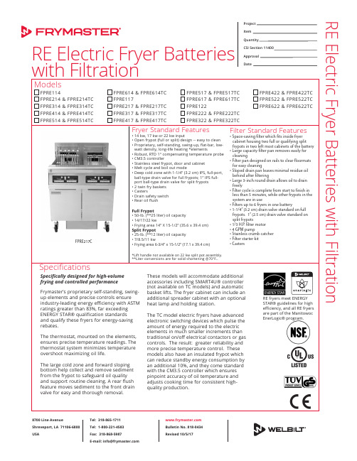
Specifically designed for high-volume frying and controlled performanceFrymaster’s proprietary self-standing, swing-up elements and precise controls ensure industry-leading energy efficiency with ASTM ratings greater than 83%, far exceeding ENERGY STAR® qualification standards and qualify these fryers for energy-saving rebates.The thermostat, mounted on the elements, ensures precise temperature readings. The thermostat system minimizes temperature overshoot maximizing oil life.The large cold zone and forward sloping bottom help collect and remove sediment from the frypot to safeguard oil quality and support routine cleaning. A rear flush feature moves sediment to the front drain valve for easy and thorough removal.SpecificationsRE Electric Fryer Batteries RE Electric Fryer Batteries with FiltrationProject ItemQuantityCSI Section 11400Approval Date8700 Line AvenueShreveport, LA 71106-6800USATel: 318-865-1711Tel: 1-800-221-4583Fax: 318-868-5987E-mail:****************** Bulletin No. 818-0434Revised 10/5/17FPRE217CRE fryers meet ENERGY STAR® guidelines for high efficiency, and all RE fryers are part of the Manitowoc EnerLogic® program.Options & AccessoriesS plit frypots E xternal oil discharge -- available on built-in filter batteries of 2 or more frypots or a frypot/spreader -- must specify front or rear connection A utomatic basket lifts (units with basket lifts require CM3.5 or 3000 controller) R E Controllers: Digital or SMART4U® 3000. RETC -- no controller options S preader cabinet -- must fit within a 6-cabinet fryer battery F rypot cover(s) F ull basket T riplet basket C risper tray S ediment tray S plash shieldBASIC DOMESTIC kwELEMENTS/FRYPOTCONTROLS/FRYPOT FILTERBASKET LIFTS/FRYPOT VOLTAGE *3 PHASE **1 PHASE RE14***RE14TC 14208V 240V 480V 39 A 34 A 17 A 67 A 58 A N/A 1 A 1 A 120V 1 A 5 A 4 A 120V 8 A 2 A 2 A 120V 3 A RE14-2***RE14-2TC 7RE17***RE17TC 17208V 240V 480V 48 A 41 A 21 A 82 A 71 A N/A 1 A 1 A 120V 1 A 5 A 4 A 120 V 8 A 2 A 2 A 120V 3 A RE17-2***RE17-2TC 8.5RE22***RE22TC 22208V 240V 480V61 A 53 A 27 A106 A 92 A N/A1 A 1 A 120V 1 A5 A 4 A 120 V 8 A2 A 2 A 120V3 ARE22-2***RE22-2TC 11BASIC EXPORT & CERE14RE14TC 14220V/380V 230V/400V 240V/415V ****250/430V 22 A 21 A 20 A 20 A N/A1 A 1 A 1 A 1 A 4 A 4 A 4 A 4 A2 A 2 A 2 A 2 A RE14-2RE14-2TC 7RE17RE17TC 17220V/380V 230V/400V 240V/415V ****250/430V 26 A 25 A 24 A 25 A N/A1 A 1 A 1 A 1 A 4 A 4 A 4 A 4 A2 A 2 A 2 A 2 A RE17-2RE17-2TC 8.5RE22RE22TC 22220V/380V 230V/400V 240V/415V ****250/430V34 A 32 A 31 A 32 AN/A1 A 1 A 1 A 1 A4 A 4 A 4 A 4 A2 A 2 A 2 A 2 ARE22-2RE22-2TC11R E E l e c t r i c F r y e r B a t t e r i e s w i t h F i l t r a t i o nPOWER REQUIREMENTS8700 Line AvenueShreveport, LA 71106-6800USATel: 318-865-1711Tel: 1-800-221-4583Fax: 318-868-5987E-mail:****************** Bulletin No. 818-0434Revised 10/5/17NOTES • T C models not available in 480V.• O ne cord is provided per full and dual split frypot on 3 phase 14 kW and 17 kW models.• C ord is provided on 3 phase units with exception of items in red (see chart above).• P lug is optional accessory on units shipping with cord, except 480V 3 phase -- no plug is available. Canada is an exception and cords, where available, must have a plug attached.• O ptional plug -- (Domestic NEMA #15-60P).• A ll 22 kw and single phase units must be field wired. No cord or plug provided. Check electrical codes for proper supply line sizing. Single phase fryers with single filter available in 240V and 208V only.• C ontroller, filter pump and basket lifts are powered by element voltages except for 480V fryers.• A ll 480 volt models are provided with separate 120 volt cord and plug for filter pump, and/or controller, and/or basket lifts.CLEARANCE INFORMATIONA minimum of 24” (61 cm) should be provided at the front of the unit for servicing and proper operation, 6” (15.2 cm) between the sides and rear of the fryer to any combustible material.We reserve the right to change specifications appearing in this bulletin without incurring any obligation for equipment previously or subsequently sold.Check for updates.*3 PH/3 Wire/Plus Ground Wire.**1 PH/2 Wire/Plus Ground Wire.***TC models not available in 480V.**** A ustralia filter models only -- when operating at 250V, elements will be rated atapproximately 15.2/18.5/23.9 kw.8700 Line Avenue Shreveport, LA 71106-6800 USA Tel: 318-865-1711Tel: 1-800-221-4583Fax: 318-868-5987E-mail:******************Bulletin No. 818-0434Revised 10/5/17R E E l e c t r i c F r y e r B a t t e r i e s w 8700 Line AvenueShreveport, LA 71106-6800USATel: 318-865-1711Tel: 1-800-221-4583Fax: 318-868-5987E-mail:****************** Bulletin No. 818-0434Revised 10/5/17We reserve the right to change specifications appearing in this bulletin without incurring any obligation for equipment previously or subsequently sold.Check for updates.。
烤鸡店设备清单明细
烤鸡店设备清单明细1、炸炉制作油炸食品的核心设备之一,有电燃气炉和电炸炉两类之分,市场上主要是电炸炉。
小型电炸炉价格便宜,XXX-XXX之间即可购得。
大型的油炸炉需要XXXX元左右。
2、腌制机用于处理一些腌制食材,腌制机能够减少和控制腌制时间,提升腌制食品的口味。
一般的商用腌制机需要XXXX元左右。
3、滤油车滤油车用于通过滤油中的杂质和其他油水混合物,省油的同时延长油的使用寿命,保证炸鸡的口感和味道。
滤油车价格在XXXX元左右。
4、陈列保温柜陈列保温柜是炸鸡店用来放置食品和展示食品的地方,有保湿保温保质的作用,也是必须设备之一,小型的陈列保温柜价格在XXXX元左右。
5、裹粉台裹粉台用于给食材裹粉以便进行油炸,裹粉台价格在XXX元左右。
6、烤箱制作烤鸡腿、烤鸡翅等等食品的设备,不同品牌和规格的烤箱价格差别很大,商用烤箱的价格至少需要XXX元。
7、开水器开水器可以方便用水,一般选用节能省电的产品,价格XXX元。
8、可乐机可乐机是炸鸡店比较昂贵的设备之一,用来制作可乐和其他饮料,价格在XXXX元左右。
9、冰柜炸鸡店的肉制品必须进行冷冻保鲜,冰柜要选择耐用的产品,价格在XXXX-XXXX元。
10、微波炉用来加热食品,价格XXX元。
11、油烟机炸鸡产品不会产生很多油烟,选择油烟机不用太贵,XXX元左右的廉价油烟机就够用了。
12、中心岛中心岛用来放陈列保温柜和可乐机这类设备,可以根据需要进行定做,价格在XXXX元左右。
13、收银机收银机方便营业员收银结账,自动结算和打印账单,不同的收银系统功能不同,一些收银机还能自动接外卖单,价格在1000元左右。
油炸机操作规程

油炸机操作规程
《油炸机操作规程》
一、安全操作规程
1. 操作人员必须穿着符合安全要求的工作服和防护用具。
2. 在使用油炸机之前,必须检查设备是否完好,电源是否接地,电气设备是否正常,防护装置是否齐全。
3. 油炸机操作过程中,严禁穿戴松动的衣物、饰品等,避免发生危险情况。
4. 操作人员需严格遵守操作规程,不得擅自拆卸或更改设备结构和参数。
二、油炸机操作规程
1. 打开油炸机电源,待设备预热完成后,将需要炸制的食材放入炸篮中。
2. 调节油炸机的温度和时间,根据食材及工艺要求进行合理的设定。
3. 将炸篮放入炸油中,严禁将手伸入油炸机内部或接触加热部件。
4. 在炸制过程中,及时观察食材的炸制情况,避免出现过度炸制或炸制不均匀的情况。
5. 炸制完成后,将炸篮取出,待油脂滴干后,将食材取出,并将油炸机设备关闭。
三、油炸机清洁规程
1. 在每次使用油炸机后,必须对设备进行清洁和维护,确保设备表面和炸篮的清洁。
2. 清洁过程中,要注意避免油脂溅出,使用适当的清洁剂和工具进行清洁工作。
3. 定期对油炸机设备进行内部清洁和润滑保养,确保设备的正常运转和使用寿命。
4. 清洗和维护过程中,严禁将水或清洁剂直接喷洒在加热部件上。
四、安全事故处理规程
1. 在操作过程中,如发现设备出现异常情况或故障,应立即停止使用,并及时通知维修人员进行处理。
2. 发生油炸机设备事故或其他安全事故时,操作人员应迅速采取安全措施,并及时报警。
以上便是关于油炸机操作规程的一些基本内容,希望能够帮助操作人员更加安全地使用油炸机设备,减少安全事故的发生。
- 1、下载文档前请自行甄别文档内容的完整性,平台不提供额外的编辑、内容补充、找答案等附加服务。
- 2、"仅部分预览"的文档,不可在线预览部分如存在完整性等问题,可反馈申请退款(可完整预览的文档不适用该条件!)。
- 3、如文档侵犯您的权益,请联系客服反馈,我们会尽快为您处理(人工客服工作时间:9:00-18:30)。
炸薯条炸鸡翅电炸炉和小型油炸机价格标题:可倾式蒸汽熬粥夹层锅和连续油炸机参数库号:JX138923 价格:百度搜【润联网】查询主要技术参数:PTDZ系列中型油炸生产线,是我厂具有自主知识产权的优化设计,与当今世界先进的油炸工艺相结合生产的一种实用性强的一种油炸机。
分纯油和油水混合二种系列。
纯油型优点是:油量少、油的利用率高、提温快、自动刮渣和自动循环过滤。
油水混合油炸机采用三角沉渣系统,漏斗式排渣干净卫生,清洗机器方便、无油渣。
二种机型均采用自动加温、油温自动控制,双层网带输送,集中排烟系统及网架吊起系统,该机型加热能源有燃煤直接式、燃煤间接式、导热油加热式、电加热式、气、油加热式。
油炸时间30秒至8分钟食品加工工艺,是大、中型食品加工企业的首选机型,优点是节省人工、物力,炸制食品成色好、色泽一致。
适合加工各种休闲食品、锅巴、沙琪玛、乡巴佬系列食品,豆类、牛肉、猪蹄、鸡腿、鱼及各种上浆、挂粉食品。
并可为用户制作各种成套油炸生产线。
开拓创新、永无止境是鹏福特人的奋斗目标,多年来始终坚持“人无我有、人有我先”的经营理念,紧跟世界先进技术和先进工艺的前沿,及时引进先进的技术和部件,来提高我们产品的品质。
随着社会的发展,人民生活水平的提高,人们对食品质量和卫生要求更加严格,对油炸食品的要求也标题:温控油炸锅和温控燃气烙饼机参数库号:JX138924 价格:百度搜【润联网】查询PTZ系列中型油炸生产线,是我厂具有自主知识产权的优化设计,与当今世界先进油炸工艺相结合生产的一种实用性强的一种油炸机。
分纯油和油水混合二种。
纯油型优点是:油量少、油的利用率高、提温快、自动刮渣和自动循环过滤。
油水混合油炸机采用三角沉渣系统,漏斗式排渣干净卫生,清洗机器方便、无油渣。
二种机型均采用自动加温、油温自动控制,双层网带输送,集中排烟系统及网架吊起系统,该机型加热能源有燃煤直接式、燃煤间接式、导热油加热式、电加热式、气、油加热式。
油炸时间30秒至8分钟食品加工工艺,是大、中型食品加工企业的首选机型,优点是节省人力、物力,炸制食品成色好,色泽一致。
适用加工各种休闲食品、锅巴、沙琪玛、乡巴佬系列食品,豆类、牛肉、猪蹄、鱼及各种上浆、挂粉食品。
并可为用户制作各种成套油炸生产线。
1、全程油温自动控制,温度从0----230度可随意设定,适合炸制各种工艺要求的食品。
2、加水阀设在低部油层处,任何时候加水都可以,不会影响油炸工作,并设有止回阀,这样就解决了在加水过程中如果停水,把油倒流到水管中的问题。
3、低部水设有测温装置,水温显示一目了然,而且,还可设定水温,与测量水标题:电热式油炸锅和油条油炸锅价格库号:JX138925 价格:百度搜【润联网】查询本机适用于面食、膨化类产品的油炸;炸区表表面积加大以及配有浮动的油面搅拌装置,彻底解决了油炸膨化食品的技术难题;采用高低温油结构,配备高效节能燃烧系统,自动控温,气动提升出料;实现自动化生产,产量大且节省大量人工,操作性能稳定。
基本结构:自动控温系公司是一家专业生产花生机械、食品机械的生产厂家,公司主要产品有:花生烘烤炉(电热型、燃煤型、燃气型)、花生干法(湿法)脱皮机、花生直刀切碎机、全自动油炸机、裹衣机、八角桶调味机、拌料机、糖衣机等花生机械,可以承接酒鬼花生、鱼皮花生、多味花生、花生酱等多种花生休闲食品的生产线,并无偿提供技术指导。
产品介绍;自动油炸锅款式新颖、结构合理、操作简单、升温速度快、易于清洁等特点、是快餐店、酒店、餐饮场所广泛应用的厨房设备.下面小编为大家介绍一下全自动油炸机的设计:全自动油炸锅具有锈钢材质、自动控温、炸制定时、自动除渣、并可配备循环过滤系统、清洗方便、自动补油、配备漏电保护、温度异常保护并报警、加热方式可选择电加热、液化气、天然气、煤或导热油锅炉;产品从根本上改变了传统油炸机的结构,解决了传统油炸机不能分区控温、不能自动过滤残渣等弊端,实现了全自动标题:水油炸锅和薯片油炸机价格库号:JX138926 价格:百度搜【润联网】查询电磁单缸炸炉大功率电磁炉,大功率油炸炉,大功率电磁灶,大功率电炒炉,大功率电炸炉,大功率电磁炉价格,节能电磁灶,电磁灶批发,商用电磁灶,大功率电磁灶批发,电磁炉炒炉,酒店电炒炉,大功率电磁灶维修,电磁灶维修额定功率:25KW-30KW(内设过滤网)额定电压:380V/50HZ规格尺寸:980*930*850重量体积:150KG/1.21方详细情况:1、前板,侧板采用国际钢号SUS201#磨砂不锈钢板,油缸底部用430#6厘厚;2、油缸壁用1.5mm贴塑不锈钢磨砂板;3、油缸四边加固采用SUS201#不锈钢方通38*38;4、腿用⊙51不锈钢管;5、磁感开关,数码显示器;6、机芯内部采用技术先进领先的德国IGBT模块设计;7、具有自动恒温功能(温度300度以下),时刻掌握温度。
适用说明:电磁炸炉升温快、温控装置、可限定加热温度,节约电能更省钱;适用于油炸食品加工企业详细介绍:1、高效:采用电磁加热,预热速度快,比发热管炸炉省电20-30%,省电就是省钱;2、安全:防水、防漏电、防油、防干烧保护等18重安全保护,使用更省心;3、节能:不存在热传导和热辐射标题:家用小型油炸锅和HX-25型燃气油水分离炸锅价格库号:JX138927 价格:百度搜【润联网】查询主要技术参数:技术参数:产品名称;燃气油水分离炸锅型号;HX-40L加热方式;液化石油气外形尺寸;930×530×940mm油水混合油炸机是一种多功能、水油混合式油炸设备,该设备采用了国际上最先进的水油混合油炸工艺,彻底改变了传统油炸设备的结构,从根本上解决了传统式油炸机的弊端,“油水分离”及“水在工作过程中自然冷却”是本油炸机的核心技术。
该技术的使用使本机各项指标明显优于传统产品。
本油炸机在使用中对油层进行可控式恒温,均匀加热,消除食物中的动物油,并适量供给水分,使炸品细腻、柔软,色、香、味俱佳。
油炸所产生的残渣被自动浸入水中,然后通过排污口排出,确保炸油新鲜、不酸化、无废油。
适用炸鸡、炸牛排、炸羊排、薯条等各类油炸食品。
优势:1. 节油:该机彻底改变传统油炸机结构,采用油水一体化结构。
上层放油,下层放水,油炸过程中产生的残渣全部沉入水中,不会烧焦,下层水分又不断产生水蒸气给高温的炸油补充微量水分,以保证炸油不变黑,从而延长换油周期,节约用油。
比传统用油可节油50%以上。
2. 健康环保:传统标题:双缸油炸锅和家用油炸机参数库号:JX138928 价格:百度搜【润联网】查询主要技术参数:油水混合油炸机是一种多功能、水油混合式油炸设备,该设备采用了国际上最先进的水油混合油炸工艺,彻底改变了传统油炸设备的结构,从根本上解决了传统式油炸机的弊端,“油水分离”及“水在工作过程中自然冷却”是本油炸机的核心技术。
该技术的使用使本机各项指标明显优于传统产品。
本油炸机在使用中对油层进行可控式恒温,均匀加热,消除食物中的动物油,并适量供给水分,使炸品细腻、柔软,色、香、味俱佳。
油炸所产生的残渣被自动浸入水中,然后通过排污口排出,确保炸油新鲜、不酸化、无废油。
适用炸鸡、炸牛排、炸羊排、薯条等各类油炸食品。
优势:1. 节油:该机彻底改变传统油炸机结构,采用油水一体化结构。
上层放油,下层放水,油炸过程中产生的残渣全部沉入水中,不会烧焦,下层水分又不断产生水蒸气给高温的炸油补充微量水分,以保证炸油不变黑,从而延长换油周期,节约用油。
比传统用油可节油50%以上。
2. 健康环保:传统油炸锅,所炸食品容易产生炸焦,而且多次炸的油,发黑,杂质多,所炸食品不利于健康。
而油水混合炸锅,下层的水可以过滤油中的杂质标题:烧烤油炸机和KED立式风机商用无烟电炸炉参数库号:JX138929 价格:百度搜【润联网】查询设备特点:自动搅拌:保证产品炸制的均匀度,防止产品因挤压而相互粘连。
易漂浮的产品则采用拍打式搅拌;易沉底的产品则采用刮底式搅拌。
自动控温:有效控制产品的炸制时间,避免了因疏忽而将产品炸糊的现象。
自动出料:减轻了工人的劳动强度,保证了炸制时间的一致性。
自动脱油:保证了产品的口感,节省了生产成本。
自动过滤:本机采用油水混合的油炸工艺,在炸制过程中食品中所产生的残渣自动过滤到水中,保持油面的清洁,所炸产品颜色鲜艳,更有食欲感。
油水混合油炸工艺简介:·该工艺通过限位控制、分区控温、科学利用植物油与动物油的比重关系使所炸肉类食品浸出的动物油自然沉入植物油下层,这样中上层工作油始终保持纯净,所炸食物不但色、香、味俱佳、外观干净美观、且提高了产品品质,延长货架期。
·该工艺采取了从油层中部加热的方式,控制上下油层的温度,有效缓解炸油的氧化程度,仰制酸价的升高,从而延长炸油的使用寿命。
·该工艺使炸制食品过程中产生的食物残渣、多余水份、重金属很快脱离高温区沉入低温区,随水排掉,当炸油过份干燥时,水层又可供给炸制油层适当的水份,使所炸食品不会出现焦化、炭化现象,标题:麻花油炸锅和节能油炸锅价格库号:JX138930 价格:百度搜【润联网】查询DKG-1000全自动纯油过滤油炸机油水混合油炸机是一种无烟型、多功能、节能环保式油炸设备,该设备采用了国际上最先进的油水混合油炸工艺彻底改变了传统油炸设备的结构,从根本上解决了传统油炸机的弊端,其优越性突出表现为:该工艺采取了从油层中部加热的方式,控制上下油层的温度,有效缓解炸油的氧化程度,抑制酸价的升高,从而延长炸油的使用寿命。
经过对我公司新式油炸机连续5-24小时后的油进行酸价测定,过氧化值和检验值分别是1.40和0.062g/100g,其结果远远小于国家标准,大大延长了炸油的使用周期,减少浪费,比传统油炸机节省炸油30%以上。
该工艺使炸制食品过程中产生的食物残渣、多余水份、重金属很快脱离高温区沉入低温区,最后沉入水底随水排掉,当炸油过份干燥时,水层又可供给炸制油层适当的水份,使所炸食品不会出现焦化、炭化现象,能有效控制致癌物质的产生,保证了食品的安全,确保了食用者的身体健康。
该工艺能有效控制食品含油量,所炸食物不但色、香、味俱佳、外观干净美观、且提高了产品品质,延长货架期。
本机主体使用SUS304不锈钢制作。
采用纯油过滤的方式,使用过程中可边油炸边过滤,可随时标题:LS-904台式双缸商用电炸炉和家用小型油炸机参数库号:JX138931 价格:百度搜【润联网】查询本厂电气两用炸鸭炉,在用户的使用角度下有三种使用方法;1,可以直接使用三相四线380V电源(无须使用液化气功率为12KW)。
2,也可以直接使用家用单相电220V电源(同样无需使用液化气功率12KW),需要注意的是在这种情况下用户必须使用10平方以上的电源线,以免线路承受不了。