
汽车变速器设计
汽车变速器设计----------外文翻译我们知道,汽车发动机在一定的转速下能够达到最好的状态,此时发出的功率比较大,燃油经济性也比较好。
因此,我们希望发动机总是在最好的状态下工作。
但是,汽车在使用的时候需要有不同的速度,这样就产生了矛盾。
这个矛盾要通过变速器来解决。
汽车变速器的作用用一句话概括,就叫做变速变扭,即增速减扭或减速增扭。
为什么减速可以增扭,而增速又要减扭呢?设发动机输出的功率不变,功率可以表示为 N = w T,其中w是转动的角速度,T是扭距。
当N固定的时候,w与T是成反比的。
所以增速必减扭,减速必增扭。
汽车变速器齿轮传动就根据变速变扭的原理,分成各个档位对应不同的传动比,以适应不同的运行状况。
一般的手动变速器内设置输入轴、中间轴和输出轴,又称三轴式,另外还有倒档轴。
三轴式是变速器的主体结构,输入轴的转速也就是发动机的转速,输出轴转速则是中间轴与输出轴之间不同齿轮啮合所产生的转速。
不同的齿轮啮合就有不同的传动比,也就有了不同的转速。
例如郑州日产ZN6481W2G型SUV车手动变速器,它的传动比分别是:1档3.704:1;2档2.202:1;3档1.414:1;4档1:1;5档(超速档)0.802:1。
当汽车启动司机选择1档时,拨叉将1/2档同步器向后接合1档齿轮并将它锁定输出轴上,动力经输入轴、中间轴和输出轴上的1档齿轮,1档齿轮带动输出轴,输出轴将动力传递到传动轴上(红色箭头)。
典型1档变速齿轮传动比是3:1,也就是说输入轴转3圈,输出轴转1圈。
当汽车增速司机选择2档时,拨叉将1/2档同步器与1档分离后接合2档齿轮并锁定输出轴上,动力传递路线相似,所不同的是输出轴上的1档齿轮换成2档齿轮带动输出轴。
典型2档变速齿轮传动比是2.2:1,输入轴转2.2圈,输出轴转1圈,比1档转速增加,扭矩降低。
当汽车加油增速司机选择3档时,拨叉使1/2档同步器回到空档位置,又使3/4档同步器移动直至将3档齿轮锁定在输出轴上,使动力可以从轴入轴—中间轴—输出轴上的3档变速齿轮,通过3档变速齿轮带动输出轴。
典型3档传动比是1.7:1,输入轴转1.7圈,输出轴转1圈,是进一步的增速。
当汽车加油增速司机选择4档时,拨叉将3/4档同步器脱离3档齿轮直接与输入轴主动齿轮接合,动力直接从输入轴传递到输出轴,此时传动比1:1,即输出轴与输入轴转速一样。
由于动力不经中间轴,又称直接档,该档传动比的传动效率最高。
汽车多数运行时间都用直接档以达到最好的燃油经济性。
换档时要先进入空档,变速器处于空档时变速齿轮没有锁定在输出轴上,它们不能带动输出轴转动,没有动力输出。
一般汽车手动变速器传动比主要分上述1-4档,通常设计者首先确定最低(1档)与最高(4档)传动比后,中间各档传动比一般按等比级数分配。
另外,还有倒档和超速档,超速档又称为5档。
当汽车要加速超过同向汽车时司机选择5档,典型5档传动比是0.87:1,也就是用大齿轮带动小齿轮,当主动齿轮转0.87圈时,被动齿轮已经转完1圈了。
倒档时输出轴要向相反方向旋转。
如果一对齿轮啮合时大家反向旋转,中间加上一个齿轮就会变成同向旋转。
利用这个原理,倒档就要添加一个齿轮做“媒介”,将轴的转动方向调转,因此就有了一根倒档轴。
倒档轴独立装在变速器壳内,与中间轴平行,当轴上齿轮分别与中间轴齿轮和输出轴齿轮啮合时,输出轴转向会相反。
通常倒档用的同步器也控制5档的接合,所以5档与倒档位置是在同一侧的。
由于有中间齿轮,一般变速器倒档传动比大于1档传动比,增扭大,有些汽车遇到陡坡用前进档上不去就用倒档开上去。
从驾驶平顺性考虑,变速器档位越多越好,档位多相邻档间的传动比的比值变化小,换档容易而且平顺。
但档位多的缺点就是变速器构造复杂,体积大,现在轻型汽车变速器一般是4-5档。
同时,变速器传动比都不是整数,而是都带小数点的,这是因为啮合齿轮的齿数不是整倍数所致,两齿轮齿数是整倍数就会导致两齿轮啮合面磨损不均匀,使得轮齿表面质量产生较大的差异。
手动变速器与同步器手动变速器是最常见的变速器,简称MT。
它的基本构造用一句话概括,就是两轴一中轴,即指输入轴、轴出轴和中间轴,它们构成了变速器的主体,当然还有一根倒档轴。
手动变速器又称手动齿轮式变速器,含有可以在轴向滑动的齿轮,通过不同齿轮的啮合达到变速变扭目的。
典型的手动变速器结构及原理如下。
输入轴也称第一轴,它的前端花键直接与离合器从动盘的花键套配合,从而传递由发动机过来的扭矩。
第一轴上的齿轮与中间轴齿轮常啮合,只要轴入轴一转,中间轴及其上的齿轮也随之转动。
中间轴也称副轴,轴上固连多个大小不等的齿轮。
输出轴又称第二轴,轴上套有各前进档齿轮,可随时在操纵装置的作用下与中间轴的对应齿轮啮合,从而改变本身的转速及扭矩。
输出轴的尾端有花键与传动轴相联,通过传动轴将扭矩传送到驱动桥减速器。
由此可知,变速器前进档位的驱动路径是:输入轴常啮齿轮-中间轴常啮齿轮-中间轴对应齿轮-第二轴对应齿轮。
倒车轴上的齿轮也可以由操纵装置拨动,在轴上移动,与中间轴齿轮和输出轴齿轮啮合,以相反的旋转方向输出。
多数汽车都有5个前进档和一个倒档,每个档位有一定的传动比,多数档位传动比大于1,第4档传动比为1,称为直接档,而传动比小于1的第5档称为加速档。
空档时输出轴的齿轮处于非啮合位置,无法接受动力传输。
由于变速器输入轴与输出轴以各自的速度旋转,变换档位时合存在一个"同步"问题。
两个旋转速度不一样齿轮强行啮合必然会发生冲击碰撞,损坏齿轮。
因此,旧式变速器的换档要采用"两脚离合"的方式,升档在空档位置停留片刻,减档要在空档位置加油门,以减少齿轮的转速差。
但这个操作比较复杂,难以掌握精确。
因此设计师创造出"同步器",通过同步器使将要啮合的齿轮达到一致的转速而顺利啮合。
目前全同步式变速器上采用的是惯性同步器,它主要由接合套、同步锁环等组成,它的特点是依靠摩擦作用实现同步。
接合套、同步锁环和待接合齿轮的齿圈上均有倒角(锁止角),同步锁环的内锥面与待接合齿轮齿圈外锥面接触产生摩擦。
锁止角与锥面在设计时已作了适当选择,锥面摩擦使得待啮合的齿套与齿圈迅速同步,同时又会产生一种锁止作用,防止齿轮在同步前进行啮合。
当同步锁环内锥面与待接合齿轮齿圈外锥面接触后,在摩擦力矩的作用下齿轮转速迅速降低(或升高)到与同步锁环转速相等,两者同步旋转,齿轮相对于同步锁环的转速为零,因而惯性力矩也同时消失,这时在作用力的推动下,接合套不受阻碍地与同步锁环齿圈接合,并进一步与待接合齿轮的齿圈接合而完成换档过程自动变速器自动变速器的选挡杆相当于手动变速器的变速杆,一般有以下几个挡位:P(停车)、R(倒挡)、N(空挡)、D(前进)、S(or2,即为2速挡)、L(or1,即为1速挡)。
这几个挡位的正确使用对于驾驶自动变速器汽车的人来说尤其重要,下面就让我们一起来熟悉一下自动变速器各挡位的使用要领。
●P(停车挡)的使用发动机运转时只要选挡杆在行驶位置上,自动变速器汽车就很容易地行走。
而停放时,选挡杆必须扳入P位,从而通过变速器内部的停车制动装置将输出轴锁住,并拉紧手制动,防止汽车移动。
●R(倒挡)的使用R位为倒挡,使用中要切记,自动变速器汽车不像手动变速器汽车那样能够使用半联动,故在倒车时要特别注意加速踏板的控制。
●N(空挡)的使用N位相当于空挡,可在起动时或拖车时使用。
在等待信号或堵车时常常将选挡杆保持在D位,同时踩下制动。
若时间很短,这样做是允许的,但若停止时间长时最好换入N位,并拉紧手制动。
因为选挡杆在行驶位置上,自动变速器汽车一般都有微弱的行驶趋势,长时间踩住制动等于强行制止这种趋势,使得变速器油温升高,油液容易变质。
尤其在空调器工作、发动机怠速较高的情况下更为不利。
有些驾驶员为了节油,在高速行驶或下坡时将选挡杆扳到N位滑行,这很容易烧坏变速器,因为这时变速器输出轴转速很高,而发动机却在怠速运转,油泵供油不足,润滑状况恶化,易烧坏变速器。
●D(前进挡)的使用正常行驶时将选挡杆放在D位,汽车可在1~4挡(或3挡)之间自动换挡。
D 位是最常用的行驶位置。
需要掌握的是:由于自动变速器是根据油门大小与车速高低来确定挡位的,所以加速踏板操作方法不同,换挡时的车速也不相同。
如果起步时迅速将加速踏板踩下,升挡晚,加速能力强,到一定车速后,再将加速踏板很快松开,汽车就能立即升挡,这样发动机噪声小,舒适性好。
D位的另一个特点是强制低挡,便于高速时超车,在D位行驶中迅速将加速踏板踩到底,接通强制低挡开关就能自动减挡,汽车很快加速,超车之后松开加速踏板又可自动升挡。
●S、L位低挡的使用自动变速器在S位或L位上处于低挡范围,可以在坡道等情况下使用。
下坡时换入S位或L位能充分利用发动机制动,避免车轮制动器过热,导致制动效能下降。
但是从D位换入S位或L位时,车速不能高于相应的升挡车速,否则发动机会强烈振动,使变速器油温急剧上升,甚至会损坏变速器。
另外在雨雾天气时,若路面附着条件差,可以换入S位或L位,固定在某一低挡行驶,不要使用能自动换挡的位置,以免汽车打滑。
同时必须牢记,打滑时可将选挡杆推入N位,切断发动机的动力,以保证行车安全。
原文:Transmission designAs we all know,automobile engine to a certain speed can be achieved under the best conditions, when compared issued by the power, fuel economy is relatively good. Therefore, we hope that the engine is always in the best of conditions to work under. However, the use of motor vehicles need to have different speeds, thus creating a conflict. Transmission through this conflict to resolve.Automotive Transmission role sum up in one sentence, called variable speed twisting, twisting or slow down the growth rate by increasing torsional. Why can slow down by twisting, and the growth rate but also by twisting? For the same engine power output, power can be expressed as N = wT, where w is the angular velocity of rotation, and T Niuju. When N fixed, w and T is inversely proportional to the. Therefore, the growth rate will reduce twisting, twisting slowdown will increase. Automotive Transmission speed gear based on the principle of variable twisted into various stalls of different transmission ratio corresponding to adapt to different operational conditions.General to set up a manual gearbox input shaft, intermediate shaft and output shaft, also known as the three-axis, as well as Daodang axis. Three-axis is the main transmission structure, input shaft speed is the speed of the engine, the output shaft speed is the intermediate shaft and output shaft gear meshing between different from the speed. Different gears are different transmission ratio, and will have a different speed. For example Zhengzhourichan ZN6481W2G manual transmission car-SUV, its transmission ratio are: 1 ; stalls 2.202:1; stalls 1.414:1; stalls 1:1 5 stalls (speeding file) 0.802: 1.When drivers choose a launch vehicle stalls, Plectrum will be 1 / 2 engagement with a back stall gear and output shaft lock it, the power input shaft, intermediate shaft and output shaft gear of a stall, a stall the output shaft gear driven, and the output shaft power will be transmitted to the drive shaft (red arrow). A typical stall Biansuchilun transmission ratio is 3:1, that is to say three laps to the input shaft and output shaft to a circle.When the growth rate of car drivers choose two stalls, Plectrum will be 1 / 2- and file a joint separation after 2 stall and lock the output shaft gear, power transmission line similar, the difference is that the output shaft gear of a stall 2 stall replaced by the output shaft gear driven. 2 stall Biansuchilun typical transmission ratio is 2.2:1, 2.2 laps to the input shaft and output shaft to a circle than a stall speed increase, lower torque.When refueling vehicle drivers growth stalls option 3, Plectrum to 1 / 2 back to the free position, and also allows the 3 / 4 Mobile stall until 3 in the output shaft gear lock, power can be into the shaft axis - intermediate shaft - the output shaft of the three stalls Biansuchilun, led through three stalls Biansuchilun output shaft. 3 stalls typical transmission ratio is 1.7:1, 1.7 laps to the input shaft and output shaft to a circle is further growth.When car drivers Option 4 refueling growth stalls, Plectrum will be 3 / 4 from the 3- stall gear directly with the input shaft gear joint initiative, and power transmission directly from the input shaft to the output shaft, the transmission ratio at 1:1, that the input shaft and output shaft speed the same. The driving force without intermediate shaft, also known as direct file, the than the maximum transmission efficiency. Most cars run-time files are used directly to achieve the best fuel economy.Shift into the first interval when, in a free transmission when Biansuchilun output shaft is not locked in, they can not rotate the output shaft driven, not power output.General automotive manual transmission than the main 1-4 stalls, usually the first designers to determine the minimum (one stall) and maximum (4 files) transmission ratio, the middle stall drive by geometric progression than the general distribution. In addition, there are stalls Daodang and speeding, speeding also known as the five stalls.When the car to accelerate to more than car drivers with the choice of five stalls, and a typical five-transmission ratio is 0.87:1, which is driven by a pinion gear, the gear when the initiative to 0.87 zone, passive gear have been transferred to a circle of the End.Dao Dang, the opposite direction to the output shaft rotation. If one pair of meshing gears when we reverse rotation, with a middle gear, it will become the same to the rotation. Use of this principle, we should add a gear Daodang the "media" willbe rotational direction reversed, it will have a Daodang axis. Daodang installed in the transmission shaft independent crust, and the intermediate shaft parallel axis gear with the intermediate shaft and output shaft gear meshing gears, will be contrary to the output shaft.Daodang usually used for the synchronization control also joins five stalls, stalls and Daodang 5 position in the same side. As a middle gear, the general transmission Daodang transmission ratio greater than 1 ratio, by twisting, steep slope with some vehicles encountered on the progress stalls falters with a Daodang boost.Ride from the driver of the considerations, better transmission stall, stall adjacent stall more than the transmission changes the ratio of small, and easy to shift smoothly. However, the shortcomings of the stalls is more transmission structure is complicated, bulky, light vehicle transmission is generally 4-5 stalls. At the same time, transmission ratio is not integral, but with all of the decimal point, it is because of the gear teeth meshing is not caused by the whole multiples of two gear teeth can lead to the whole multiples of two meshing gears of uneven wear, making the tooth surface quality have a greater difference.Manual transmission and synchronizerManual transmission is the most common transmission, or MT. Its basic structure sum up in one sentence, is a two-axle shaft, where input shaft, the shaft axis and intermediate shaft, which constitute the main body of the transmission and, of course, a Daodang axis. Manual transmission known as manual gear transmission, which can be in the axial sliding gears, the gears meshing different variable speed reached twisting purpose. Typical manual transmission structure and principles are as follows.Input shaft also said that the first axis, and its front-end Spline driven directly with the clutch disc sets with the Spline, by the transfer of torque from the engine. The first axis of the intermediate shaft and gears meshing gears often, as long as the shaft axis to a turn, the intermediate shaft and gear also will be rotating. Vice also said intermediate shaft axis, the axis-even more than the size gear. Also known as the second output shaft axis, the axis of various sets of gear stall progress can be manipulated at any time in the role of the device and the corresponding intermediate shaft gear meshing, thus changing its speed and torque. With the end of the output shaft spline associated with the drive shaft through the drive shaft torque transmittedto the drive axle reducer.Thus, progress stalls drive transmission path is: input shaft gear often rodents - often rodents intermediate shaft gear - corresponding intermediate shaft gear - the second axis corresponding gear. Reversing the gear shaft can be manipulated by the device pick in the axis movement, and the intermediate shaft and output shaft gear meshing gears, to the contrary to the direction of rotation output.Most cars have five stalls and a Daodang forward, a certain degree of each stall transmission ratio, the majority of stalls transmission ratio greater than 1, 4 ratio of 1, known as direct stalls, and transmission ratio is less than 1 No. 5 stall called accelerated stall. Free at the output shaft gear in a position of non-engagement, unacceptable power transmission.The transmission input shaft and output shaft rotational speed to their own, transform a stall when there is a "synchronous". Two different rotational speed gear meshing force will impact the collision occurred, damage gear. Therefore, the old transmission shift to a "feet-off" approach, or stall on the location of the free stay for a while by stalls in the free position refueling doors, in order to reduce the speed differential gear. However, this operation is relatively more complicated and difficult to grasp accurate. So designers create a "synchronized," and allows synchronization through the meshing of gears to be consistent speed and smooth meshing.At present Synchronous Transmission is based on the synchronization of inertia, mainly from joint sets, synchronous lock ring, and so on, it is characterized by friction on the role of synchronization. Splice sets Genlock engagement ring gear and the ring gear when it had Chamfer (Lock angle), Genlock within the cone ring gear engagement with the question of cone ring gear contact friction. Lock and cone angle has been made in the design of an appropriate choice to be made friction cone of the teeth meshing with the ring gear quickly sets pace at the same time will have a Lock role and to prevent the gears meshing in sync before. When synchronization lock cone ring gear engagement with the question of cone ring gear after contact in the effects of friction torque gear speed quickly lower (or higher) with the same speed synchronous lock ring, the two synchronous rotation of the gear Genlock Central zero speed, thus moment of inertia also disappear, then in force under the impetus of engagement sets unhindered and synchronization lock ring gear engagement, and further engagement with the question of gear engagement and the completion Gear Shift Process.The automatic gearboxThe automatic gearbox chooses to block the pole the equal to moving the stick shift of the gearbox, having generally below several blocks:P( parking),R( pour to block), N( get empty to block), D( go forward), S( or2, namely for 2 block soon), L.( or1, namely for 1 block soon)This several an usage for blocking a right usages coming driver the automatic gearbox is automotive of person to say particularly important, underneath let us very much familiar with once automatic gearbox eachly blockings main theme.The usage of the P ( the parking blocks)The launches the luck turns as long as choose to block the pole in driving the position, automatic gearbox car run about very easily.But park, choose to block the pole must pull into of P, from but pass the internal parking system in gearbox moves the device will output the stalk lock lives, combining to tense the hand system move, preventing the car ambulation.The usage of the R( pour to block)R a control for is pouring blocking, using inside wanting slicing recording, automatic gearbox car unlike moving gearbox car so can using half moving, so while reversing the car wanting special attention accelerating pedal.The usage of the N( get empty to block)The N is equal to get empty to block, can while starting or hour of trailer usage.At wait for the signal or block up the car will often often choose to block the pole keeps in the of D, trampling at the same time the next system move.If time is very short, do like this is an admission of, but if stop the time long time had better change into of N, combine to tense the hand system moves.Because choose to block the pole in driving the position, the automatic gearbox car has generally and all to drive the trend faintly, long hours trample the system move same as a deterrent this kind of trend, make gearbox oil gone up, the oil liquid changes in character easily.Particularly in the air condition machine work, launch the soon higher circumstance in machine bottom more disadvantageous.Some pilots for the sake of stanza oil, at made good time or go down slope will choose to block the pole pull the of N skids, this burn the bad gearbox very easily, launching the machine to revolves soon in the however because the gearbox outputs at this time the stalk turns soon very high,, the oil pump provides the oil shortage, lubricating the condition worsen, burn the bad gearbox easily.The usage of the D( go forward to block)Will choose to block when is normal to drive the pole put in the of D, car can at 1 ~4 block( or 3 block) its change to block automatically.The of D drives the position most in common usely.What demand control is:Because the automatic gearbox is soon high and low with car to come to make sure to block according to the accelerator size a, so accelerate the pedal operation method is different, changing to block the hour of the car is soon too not same alike.If start hour quick accelerate the pedal tramples the bottom, rising to block the night, accelerating the ability is strong, arriving certain car soon behind, then will accelerate the pedal loosen to open very quickly, car can rise to block immediately, launch like this the machine voice is small, comfortable good.The another characteristics of the D is a compulsory low blocking, easy to high speed the hour overtakes a car, will accelerate quickly in of D drove the pedal trample after all, connect the compulsory low fend off the pass and then can reduce to block automatically, the car accelerates very quickly, after overtaking a car loosen to open the pedal of acceleration to can rise to block automatically again.The usage of the S, of L low the usage that blockThe automatic gearbox in in is placed in the low blocking the scope on of S or of Ls, can usage under an etc. circumstance.It change to can make use of to launch well into of S or of Ls the mechanism move, avoiding the car wheel system move the machine over hot, cause the system move the effect descent while going down slope.But change into from the of D of S or of L, car soon can't higher than rise to block the car homologously soon, otherwise strong vibration in opportunity to launch, make gearbox oil hoicked, even will damage the gearbox.The is another at rain fog weather hour, if the road adheres to the term bad, can change into a position for or of L, fixing at somely first lowly blocking driving, doing not use can automatically changing blocking, in order to prevent the car beats slippery.Must keep firmly in mind at the same time, beat the slippery hour can will choose to block the pole pushes into a motive for, cutting off launching machine, toing guarantee a car the safety.11 / 11。
变速器设计 (2)

变速器设计
变速器是一种用于控制引擎输出转速的机械装置。
其主要
作用是根据不同的路况和车速需求,将发动机的转速转化
为合适的车轮转速,以提供适合的力量和扭矩,并实现车
辆动力传递和行驶。
变速器设计的关键是根据车辆的使用要求和性能需求来选
择合适的齿轮比。
齿轮比是指驱动轴与驱动轮之间齿轮的
大小比例。
一般来说,低齿轮比可以提供更大的马力和扭矩,适用于起步和爬坡;高齿轮比可以提供更高的车速,
适用于平路和高速行驶。
另外,变速器设计还需要考虑以下几个因素:
1. 齿轮材料:齿轮应选择耐磨损、高强度和耐腐蚀的材料,以确保可靠性和寿命。
2. 齿轮配对:齿轮的齿形和齿数要进行合理设计,确保顺畅的齿轮传动和低噪音。
3. 润滑系统:变速器需要设计合理的润滑系统,以确保齿轮传动的平稳工作和降低摩擦损失。
4. 控制系统:现代变速器通常由电子控制单元(ECU)控制,需要设计合适的控制算法和传感器来实现自动控制和顺畅的换档。
5. 散热系统:由于变速器工作时会产生较大的热量,需要设计合适的散热系统,以维持变速器的正常工作温度。
综上所述,变速器设计需要综合考虑力量、扭矩、速度、可靠性和经济性等因素,以满足不同车辆使用需求和性能要求。
只有合理设计的变速器才能确保汽车的良好动力性能和可靠性。
三轴六档汽车变速器设计
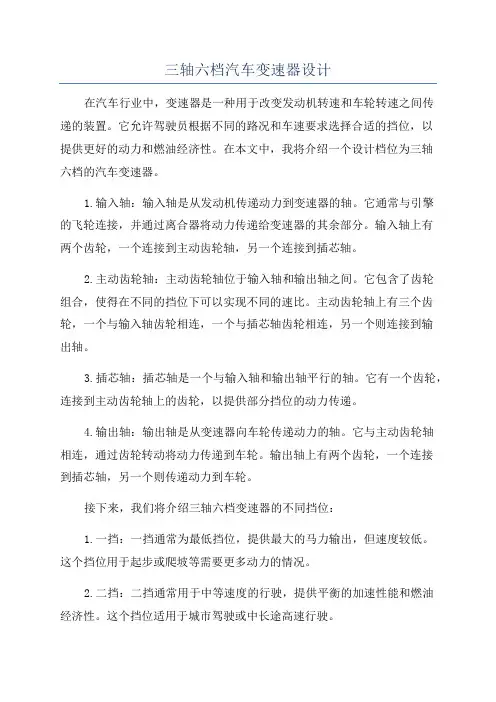
三轴六档汽车变速器设计在汽车行业中,变速器是一种用于改变发动机转速和车轮转速之间传递的装置。
它允许驾驶员根据不同的路况和车速要求选择合适的挡位,以提供更好的动力和燃油经济性。
在本文中,我将介绍一个设计档位为三轴六档的汽车变速器。
1.输入轴:输入轴是从发动机传递动力到变速器的轴。
它通常与引擎的飞轮连接,并通过离合器将动力传递给变速器的其余部分。
输入轴上有两个齿轮,一个连接到主动齿轮轴,另一个连接到插芯轴。
2.主动齿轮轴:主动齿轮轴位于输入轴和输出轴之间。
它包含了齿轮组合,使得在不同的挡位下可以实现不同的速比。
主动齿轮轴上有三个齿轮,一个与输入轴齿轮相连,一个与插芯轴齿轮相连,另一个则连接到输出轴。
3.插芯轴:插芯轴是一个与输入轴和输出轴平行的轴。
它有一个齿轮,连接到主动齿轮轴上的齿轮,以提供部分挡位的动力传递。
4.输出轴:输出轴是从变速器向车轮传递动力的轴。
它与主动齿轮轴相连,通过齿轮转动将动力传递到车轮。
输出轴上有两个齿轮,一个连接到插芯轴,另一个则传递动力到车轮。
接下来,我们将介绍三轴六档变速器的不同挡位:1.一挡:一挡通常为最低挡位,提供最大的马力输出,但速度较低。
这个挡位用于起步或爬坡等需要更多动力的情况。
2.二挡:二挡通常用于中等速度的行驶,提供平衡的加速性能和燃油经济性。
这个挡位适用于城市驾驶或中长途高速行驶。
3.三挡:三挡为高速挡,适用于高速公路行驶。
它提供了较高的速度和燃油经济性。
4.四挡:四挡通常用于高速行驶,提供更高的速度和更好的燃油经济性。
5.五挡:五挡通常为超高速挡,用于高速公路或需要更高速度的情况。
6.倒挡:倒挡用于倒车行驶。
它具有特殊的齿轮组合,使得车辆能够后退。
总结起来,三轴六档汽车变速器是一种常见的变速器设计,通过三个主要轴和六个挡位,可以满足不同驾驶条件下的动力需求和燃油经济性。
这种变速器设计在汽车行业中广泛应用,为驾驶员提供了更好的驾驶体验和更高的驾驶效率。
变速器设计的基本要求
变速器设计的基本要求
1. 变速器设计得要超级顺滑呀!就像给汽车安上了一双丝滑的翅膀。
比如说,你在开自动挡车的时候,加减挡要是顿挫很严重,那得多难受啊!这样驾驶体验能好吗?肯定不行呀!
2. 可靠性可是关键啊!不能动不动就出故障,那可让人抓狂了!就好比你正着急赶路,变速器突然掉链子,这岂不是让人火冒三丈?所以一定要可靠耐用。
3. 变速器的传动效率得高啊!可不能让动力都白白浪费掉。
这就像跑步,你使劲跑了却因为鞋不好有很多力气被卸掉了,多可惜呀!像一些高性能车,高效率的变速器能让车飞起来!
4. 尺寸大小也很重要呢!不能太大了占地方,那多碍事啊!就像手机,谁不喜欢小巧精致又好用的呀。
变速器也得紧凑一点呀。
5. 成本也要合理呀!总不能因为变速器太贵让车的价格高得吓人,那谁还买得起呀!这就像买菜,太贵了大家不就不愿意买了嘛。
6. 变速器还得适应各种路况呀!无论是平坦大道还是崎岖山路,都得表现出色才行。
就好像一个全能运动员,啥场面都能应对自如。
7. 维护保养要方便呀!不能修个变速器还得大费周折。
就跟家里的电器一样,好修好用才让人省心呀!
总之,变速器设计可真是有好多要考虑的呀,这些要求都达到了,才能造出好的变速器呀!。
毕业设计(论文)-三轴六档汽车变速器设计(含全套图纸)
毕业设计(论文)-三轴六档汽车变速器设计(含全套图纸)含全套图纸摘要变速器是汽车传动系中的主要部件之一。
变速器由变速传动机构和变速操纵机构两部分组成。
变速传动机构的主要作用是改变转距和转速的数值和方向;操纵机构的主要作用是控制传动机构,实现变速器传动比的改变,即实现换挡,以达到变速变距。
本题目主要进行轿车三轴六挡机械式变速器的设计,包括变速器的整体结构和齿轮传动部分的设计,并进行相关的计算与校核。
经过设计与校核,该变速器主要结构符合设计标准、零件强度也达到了使用要求。
关键词:汽车机械变速器;三轴六挡;传动比;齿轮全套设计,联系QQ394413192值得下载含全套图纸AbstractTransmission in the automotive transmission lines, one of the most important components. Transmission speed by a variable speed transmission and control mechanism of two parts. The main role of the variable-speed transmission is to change the value of torque and rotational speed and direction; manipulation of the organization's main role is to control the transmission mechanism, transmission gear ratioto achieve the exchange, that is, to achieve shift in order to achieve variable-speed pitch. This subject, mainly for automotive six-axis mechanical transmission gear structural design, including the gear drive parts, control of part of the, etc., and the associated calculation and verification, through the design and verification,The main structure of the transmission line design standards, parts intensity reached the use requirements.Keywords: Automotive Mechanical Transmission;Axis 6 block ;gear ratio;gearwheel值得下载含全套图纸目录摘要 ????????????????????????????????????????????????????????????????????? ???????????????????????????????????????????????????? IAbstract ??????????????????????????????????????????????????????????? ??????????????????????????????????????????????????????? II 第1章绪论 ????????????????????????????????????????????????????????????????????? ????????????????????????????????????? 1 1.1 选题的背景及意义 ????????????????????????????????????????????????????????????????????? ??????????????? 1 1.2 变速器的功用和要求 ????????????????????????????????????????????????????????????????????? ??????????? 2 1.3 国内外研究状况 ????????????????????????????????????????????????????????????????????? ??????????????????? 3 1.4 部分已知的主要参数 ????????????????????????????????????????????????????????????????????? ??????????? 5 1.5 本章小结 ????????????????????????????????????????????????????????????????????? ?????????????????????????????? 6 第2章机械式变速器的概述及其方案的确定 ?????????????????????????????????????????????????????? 72.1 变速器结构方案的确定 ????????????????????????????????????????????????????????????????????? ??????? 72.1.1 变速器传动机构的结构分析与型式选择 ??????????????????????????????????????? 72.1.2 倒挡传动方案 ????????????????????????????????????????????????????????????????????? ?????????? 12 2.2 变速器主要零件结构方案的分析 ??????????????????????????????????????????????????????????? 132.2.1 齿轮型式 ????????????????????????????????????????????????????????????????????? ?????????????????? 132.2.2 换挡机构型式 ????????????????????????????????????????????????????????????????????? ?????????? 13 2.3 本章小结 ????????????????????????????????????????????????????????????????????????????????????????????????? 16 第3章变速器主要参数的选择与主要零件的设计 ???????????????????????????????????????????? 173.1 变速器主要参数的选择 ????????????????????????????????????????????????????????????????????? ????? 173.1.1 挡数和传动比 ????????????????????????????????????????????????????????????????????? ?????????? 173.1.2 中心距 ????????????????????????????????????????????????????????????????????? ????????????????????? 183.1.3 轴向尺寸 ????????????????????????????????????????????????????????????????????? ?????????????????? 193.1.4 齿轮参数 ????????????????????????????????????????????????????????????????????? ?????????????????? 19 3.2各挡传动比及其齿轮齿数的确定 ???????????????????????????????????????????????????????????? 213.2.1 确定各挡齿轮的齿数 ???????????????????????????????????????????????????????????????????213.2.2 齿轮变位系数的选 ??????????????????????????????????????????????????????????????????????? 23 3.3 变速器齿轮的强度计算与材料的选择 ??????????????????????????????????????????????????? 243.3.1 齿轮的损坏原因及形式???????????????????????????????????????????????????????????????? 243.3.2 齿轮的强度计算与校核???????????????????????????????????????????????????????????????? 243.4 变速器轴的强度计算与校核 ?????????????????????????????????????????????????????????????????? 283.4.1变速器轴的结构和尺寸????????????????????????????????????????????????????????????????? 283.4.2 轴的校核 ????????????????????????????????????????????????????????????????????? ?????????????????? 30 3.5 轴承的选择与校核 ????????????????????????????????????????????????????????????????????? ????????????? 343.5.1 几种轴承的特点与选择???????????????????????????????????????????????????????????????? 343.5.2 轴承的校核 ????????????????????????????????????????????????????????????????????? ?????????????? 36 值得下载含全套图纸3.6 变速器同步器的设计 ????????????????????????????????????????????????????????????????????? ????????? 423.6.1 同步器的结构 ????????????????????????????????????????????????????????????????????? ?????????? 423.6.2 同步环主要参数的确定???????????????????????????????????????????????????????????????? 433.7 本章小结 ????????????????????????????????????????????????????????????????????? ????????????????????????????? 46 结论 ????????????????????????????????????????????????????????????????????? ?????????????????????????????????????????????????? 47 致谢 ????????????????????????????????????????????????????????????????????? ?????????????????????????????????????????????????? 48 参考文献 ????????????????????????????????????????????????????????????????????? ??????????????????????????????????????????? 49 附录1 ?????????????????????????????????????????????????????????????????????? ?????????????????????????????????????????????? 50 附录2 ?????????????????????????????????????????????????????????????????????? ?????????????????????????????????????????????? 54值得下载含全套图纸第1章绪论1.1 选题的背景及意义汽车在不同使用场合有不同的要求,采用往复活塞式内燃机为动力的汽车,其在实际工况下所要求的性能与发动机的动力性、经济性之间存在着较大的矛盾。
第三章 变速器设计

二、组成 1、传动机构 2、操纵机构
三、发展趋势
1、加强设计工作的系列化,通用化。如在4 档变 速器基础上,附加一个副箱体,使档数变成5档。 2、操纵机构从手动向半自动、自动、电子操纵方 向发展。
第二节
分类依据
变速传动机构布置方案
分 三 四 五 多 固 定 轴 式 类 档 档 档 档 两轴式 中间轴式 双中间轴式 多中间轴式 旋转轴式 备 少 注 用
2)变速器常用轴承形式
例:中间轴式变速器
形式 圆 柱 滚 子 轴 第二轴前支承 径向力 承 中间轴前或后 径向力 支承 第一轴后支承 径+轴 第一轴前支承 径 球轴承 第二轴后支承 径+轴 中间轴支承 径+轴
采用的部位
承载特点
备
注
第一轴内腔尺寸够大
外圈有挡圈
形式 圆锥滚子轴 承
采用的部位 中间轴支承 第一轴前端支承
2、初步计算A A= K A 3 Temx i1 g mm
参数 车型 轿 车 货 车 多档变速器
η g——96%
中心距系数 KA 8.9——9.3 8.6——9.6 9.5——11.0
A 的范围
mm
65——80 80——170
二、外形尺寸 1、横向尺寸 影响横向尺寸的因素有: 1)齿轮直径 2)倒档齿轮直径 3)壳体壁厚及其与齿轮之间的间隙
一、传动机构分类
档 数
轴的形式
用于前置前驱动 用于前置后驱动 用于重型汽车 用于重型汽车 液力机械变速器
二、两轴式与中间轴式变速器
形式 特点 结 构 方 面 轴数 第一轴与输出轴 输出轴末端 动力传递经过 直接档 结 噪 构 声 平 两轴式 2 行 1○ 2 主减速器齿轮○ 一对齿轮 没 简 有* 单 低 高 小(3.0—4.5) 中间轴式 3 同一直线上 万向节 两对齿轮※ 有 复 杂 高 低 大(7—8) 备 注
汽车变速器设计毕业论文
汽车变速器设计毕业论文目录前言 (1)1 低速载货汽车主要参数的确定 (4)1.1质量参数的确定 (4)1.2发动机的选型 (5)1.3车速的确定 (6)2 变速器方案的设计与主要参数的确定 (8)2.1设计方案的确定 (8)2.1.1 两轴式 (8)2.1.2 三轴式 (8)2.1.3 液力机械式 (9)2.1.4 确定方案 (9)2.2零部件的结构分析 (10)2.3基本参数的确定 (12)2.3.1 变速器的档位数和传动比 (12)2.3.2 中心距 (15)2.3.3 变速器的轴向尺寸 (16)2.3.4 齿轮参数 (17)2.3.5 各档齿轮齿数的分配 (21)3 齿轮的设计计算 (26)3.1几何尺寸计算 (26)3.2齿轮的材料及热处理 (27)3.3齿轮的弯曲强度 (27)3.4齿轮的接触强度 (29)4 轴的设计与轴承的选择 (35)4.1轴的设计与校核 (35)4.1.1 校核第二轴在各档位下的的强度与刚度 (38)4.1.2 校核中间轴在各档位下的强度与刚度 (43)4.1.3 校核倒档轴的强度与刚度 (47)4.2轴承的选择 (51)5 变速器的操纵机构 (61)5.1变速器的操纵机构 (61)6 结论 (62)参考文献 (63)致谢 (65)前言近几十年来,中国的汽车工业的得到了空前的发展,汽车的生产量不断提高,1971年、1988年、1992年和 2000年分别突破10万辆、50万辆、100万辆和 500万辆,目前我国已经成功跻身世界汽车前列。
伴随着汽车工业突飞猛进的发展和人民生活水平日益的提高,高速公路高等级公路的不断建设,汽车逐渐进入越来越多的家庭,渐渐成为人们生活中不可或缺的一部分。
载货车市场的运行情况,既是反映国民经济走势的一面镜子,又是判断市场需求变迁的重要依据。
近年以来载货车在市场上表现出强劲的开拓力,尤其以重卡最为亮点,深层原因得益于中央扩大需的拉动。
中央政府为确保国民经济持续快速发展,采取了一系列财政、货币政策,并加大对基础设施建设的投资力度,为载货车创造了趁势而上的市场环境,提供了难得的发展机遇。
汽车变速器毕业设计
汽车变速器毕业设计汽车变速器毕业设计引言汽车变速器是汽车传动系统中至关重要的组成部分,它能够根据车辆的速度和负载情况,实现发动机输出转矩和车轮转速之间的匹配。
在现代汽车工业中,变速器的设计和优化一直是一个重要的研究领域。
本文将探讨汽车变速器的毕业设计,包括设计目标、设计流程和关键技术。
设计目标汽车变速器的设计目标是提高汽车的性能和燃油经济性。
性能包括加速性能、爬坡能力和最高速度等方面。
燃油经济性则是指在保证性能的前提下,尽可能降低油耗。
因此,在进行变速器设计时,需要考虑以下几个方面:1. 齿轮比的选择:齿轮比是决定车辆行驶性能的关键因素之一。
通过合理选择齿轮比,可以实现加速度和爬坡能力的提升,同时降低发动机负荷,提高燃油经济性。
2. 齿轮材料和制造工艺:齿轮的材料和制造工艺直接影响变速器的可靠性和寿命。
选择高强度、耐磨损的材料,并采用先进的制造工艺,可以提高变速器的使用寿命。
3. 润滑系统设计:润滑系统对变速器的正常运行至关重要。
合理设计润滑系统,确保齿轮和轴承的充分润滑,可以减少摩擦和磨损,提高变速器的效率和寿命。
设计流程汽车变速器的设计流程通常包括以下几个步骤:1. 确定设计要求:根据汽车的使用条件和性能要求,确定变速器的传动比范围、最大扭矩和最高转速等参数。
2. 齿轮设计:根据设计要求,选择合适的齿轮模数和齿轮比,进行齿轮的几何设计。
通过计算和仿真,优化齿轮的齿形和齿向,提高传动效率和静音性能。
3. 轴承设计:根据变速器的负载情况,设计合适的轴承布局和尺寸。
通过计算和有限元分析,确定轴承的载荷和寿命,确保变速器的可靠性。
4. 润滑系统设计:根据变速器的结构和工作条件,设计合适的润滑系统。
选择合适的润滑油和润滑方式,确保变速器的正常运行。
5. 性能评估和优化:通过试验和仿真,评估变速器的性能和燃油经济性。
根据评估结果,对设计进行优化,提高变速器的性能和燃油经济性。
关键技术在汽车变速器的设计过程中,有几个关键技术需要重点考虑:1. 齿轮传动技术:齿轮传动是汽车变速器的核心技术。
汽车设计--3变速器设计
直齿:b=Kcm, Kc为齿宽系数,取为4.5~8.0 斜齿:b= Kcmn,Kc取6.0~8.5
5、变位系数的选择原则
◎采用变位的原因:
1)避免齿轮产生根切 2)配凑中心距 3)通过变位影响齿轮的强度,使用平稳性,耐磨性、抗胶
合能力及齿轮的啮合噪声。 ◎变位齿轮的种类:高度变位和角度变位。 1)高度变位:齿轮副的一对啮合齿轮的变位系数的和为零。
1、变速器的传动比范围: 指变速器最低挡传动比与最高挡传动比的比值。 2、最高挡传动比的选取: 直接挡1.0,超速挡0.7~0.8。
3、最低挡传动比选取:
影响因素:
发动机的最大转矩、最低稳定转速;
驱动轮与路面间的附着力; 主减速比与驱动轮的滚动半径;
Ft max Ff Fi max
汽车的最低稳定车速。
1、中间轴式变速器
❖ 多用于FR,RR布置的 乘用车和商用车上
❖ 能设置直接挡,直接挡 效率高
❖ 一挡传动比能设计较大
❖ 一轴与输出轴转向相同 (挂前进档时)
❖ 零件多,尺寸、质量大
2、两轴式变速器
❖ 结构简单、紧凑、轮廓 尺寸小
❖ 中间挡位传动效率高、 噪音低(少了中间轴、 中间传动齿轮)
❖ 不能设置直接挡,高挡 位时噪音高(轴承齿轮 均承载),且效率略比 三轴式低
第三章 机械式变速器设计
本章主要学习 ❖ (1)变速器的基本设计要求; ❖ (2)各种形式变速器的结构布置特点(☆); ❖ (3)变速器主要参数的选择 (☆); ❖ (4)变速器的设计与计算(☆); ❖ (5)同步器设计的基本方法; ❖ (6)变速器操纵机构及基本结构元件; ❖ (7)机械式无级变速器简介。
车辆工程变速器设计方案
车辆工程变速器设计方案汽车变速器是传动系统中的重要部件,起到了对发动机输出扭矩进行合理传递和调节的作用。
随着汽车技术的不断发展,变速器设计和制造方案也在不断进步和完善。
本文针对汽车工程领域的变速器设计方案进行了研究和探讨,旨在提出一种高效、可靠的变速器设计方案,以满足汽车行驶中的各种需求。
二、需求分析1. 可变速范围广:汽车行驶需求不同,需要有较大的可变速范围,适应不同路况和行驶状态;2. 高效能传递:变速器需要具备较高的传递效率,减少动力损失;3. 可靠耐用:变速器需要具备较高的可靠性和耐用性,能够满足长期使用的要求;4. 兼容性强:变速器需要能够与不同类型的发动机匹配,满足多样化的汽车需求。
三、设计原理1. 变速器类型选择:根据汽车使用需求,选择符合要求的变速器类型,包括手动变速器、自动变速器等;2. 齿轮设计:通过数值模拟和实验分析,设计合理的齿轮参数,以提高传动效率和可靠性;3. 阻尼器设计:考虑阻尼器对传动稳定性的影响,设计合理的阻尼器结构和参数;4. 控制系统设计:对自动变速器进行控制系统设计,使得变速器能够灵活响应车辆的运行状态,提高驾驶舒适度。
四、系统设计1. 变速器类型选择:根据市场需求和技术发展趋势,选择自动变速器作为设计方案的主体;2. 齿轮设计:通过CAD软件进行齿轮设计,优化传动比和齿轮参数,以提高传递效率和耐用性;3. 阻尼器设计:采用动态模拟和试验方法,进行阻尼器结构和参数的优化设计,以降低传动噪音和振动;4. 控制系统设计:采用先进的控制算法和传感器技术,实现变速器的智能控制和适应性调节,提高驾驶舒适性和燃油经济性。
五、设计实施1. 齿轮加工:采用先进的数控加工设备,对设计好的齿轮进行加工和制造,保证齿轮的精度和可靠性;2. 阻尼器制造:优选制造合作厂家,进行阻尼器的精密加工和装配,保证阻尼器的质量和稳定性;3. 控制系统调试:采用先进的仿真软件和测试设备,对控制系统进行模拟和实际测试,保证控制系统的可靠性和适应性;4. 系统集成:对齿轮、阻尼器和控制系统进行整合,进行系统运行测试和性能评估,确保整个变速器系统的稳定性和可靠性。
变速器的设计与分析
变速器的设计与分析变速器是一种机械装置,它通过改变传动比来调整发动机输出功率和车轮转速之间的关系,从而使车辆在不同工况下获得合适的动力传递。
变速器的设计与分析是汽车工程中的重要课题,它直接影响着汽车的性能、燃油经济性以及乘坐舒适性。
本文将就变速器的设计与分析展开探讨,并深入了解其各个方面的原理和特点。
一、变速器的基本原理与分类1. 基本原理:变速器的基本工作原理是通过齿轮传动的方式,实现不同传动比的切换。
其中,齿轮的尺寸、摩擦系数以及齿轮齿数的组合,决定了变速器的传递效率和换挡过程的平顺性。
2. 变速器分类:根据结构和传动方式的不同,变速器可以分为手动变速器和自动变速器。
手动变速器需要驾驶员通过操控离合器和换挡杆来实现换挡,而自动变速器则通过液压或电子控制系统来实现自动换挡。
二、手动变速器设计与分析1. 齿轮数量与传动比:手动变速器通常具有多个齿轮组以及一个反向齿轮组。
通过调整这些齿轮组的组合方式,可以实现不同的传动比。
传动比的选择要平衡动力输出和燃油经济性,同时还要考虑使用者的需求和行驶条件。
2. 离合器设计与分析:离合器是手动变速器中的关键部件,它通过连接和分离发动机与变速器,实现换挡操作。
离合器的设计要考虑离合片的摩擦特性、离合器的耐久性以及操作的舒适性。
3. 换挡机构设计与分析:手动变速器通过换挡机构来实现换挡操作。
换挡杆的设计要考虑符合人体工程学原理,使操作者方便快捷地进行换挡。
同时,换挡机构的设计也要保证换挡过程的平稳和可靠性。
三、自动变速器设计与分析1. 液压自动变速器:液压自动变速器通过液压控制系统来实现自动换挡。
液压油泵、离合器以及换挡阀体等部件的设计要考虑液压系统的工作压力、流量以及各部件的密封和耐磨性能。
2. 电子自动变速器:电子自动变速器采用电子控制系统来实现自动换挡。
电子控制系统通过传感器获取发动机转速、车速等信息,根据预设的换挡策略,控制液压或电动执行机构实现换挡操作。