CF 说明书
奥林巴斯(Olympus)CF PCF GIF SIF内窥镜清洁和消毒检查表说明书

3. Activate the flushing pump for 10 seconds.
4. Detach the MAJ-855/disposable attachment cap MAJ-1652 from the flushing pump.
2. Immerse the distal tip in water. 3. Fill a 30 ml syringe with water, attach to the MAJ-855, and
flush 30mls of water. 4. Fill a 30 ml syringe with air, attach to the MAJ-855, and flush
SIF
SIF-Q180
CF-H190L/I CF-Q180AL/I
PCF-H190L/I
GIF-H190 GIF-H180 GIF-XTQ160
CF-H180DL/I
PCF-PH190L/I
PCF-H180AL/I
GIF-XP190N GIF-XP180N
GIF-1TH190 GIF-N180
Transport to reprocessing area in a covered container.
Comments:
Leakage Testing
1. Fill a basin with clean water.
2.
Detach air/water channel cleaning adapter, suction valve, and biopsy valve from the endoscope.
CF100L流量开关 说明书
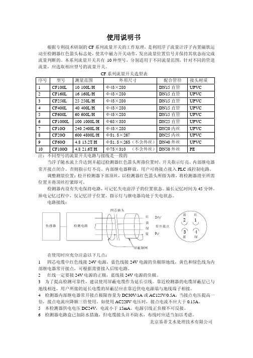
使用说明书根据专利技术研制的CF 系列流量开关的工作原理,是利用浮子流量计浮子内置磁铁运动至检测器红色箭头标志处,使其中磁力开关动作,发出流量位置信号并保持其状态而完成流量判断的。
本系列流量开关共有 10种型号,分别适用于不同流量范围,针对不同的管道流量,应选取相应型号的流量开关。
CF 系列流量开关选型表序号 型号 测量范围 外形尺寸 配合管径 接头材质 1 CF100L 10-100L/H Φ45×280 DN15直管 UPVC 2 CF160L 16-160L/H Φ45×280 DN15直管 UPVC 3 CF250L 25-250L/H Φ45×280 DN15直管 UPVC 4 CF400L 40-400L/H Φ45×280 DN15直管 UPVC 5 CF600L 60-600L/H Φ45×280 DN15直管 UPVC 6 CF1000L 100-1000L/H Φ68×380 DN25直管 UPVC 7 CF10G 240-2400L/H Φ45×280 DN20内丝 UPVC 8 CF20G 600-4800L/H Φ51.5×267 DN25内丝 UPVC 9 CF60G 4.8-13.2T/H Φ51.5×265(不含外丝)DN40外丝 UPVC 10 CF100G 4.8-21.6T/H Φ75×310 (不含外丝)DN50外丝 PE 注:不同型号的流量开关电路与接线是一致的当浮子随水流上升达到并超过检测器红色箭头所指位置时,开关指示灯亮、内部继电器常开接点闭合。
否则指示灯不亮、内部继电器释放。
用户可将接点接入PLC 或控制电路。
调整测量位置:松开检测器下部顶丝,以检测器红色箭头所指为准,将检测器滑至所需位置并将顶丝拧紧即可。
检测器内设有失电保持电路,可记忆失电前浮子的位置状态。
CFP30 3kW 工业风暖器说明书

3kW Industrial Fan Heater08/19563/2 (UK) Issue 2The product complies with the European Safety Standards EN60335-2-30 and the European Standard Electromagnetic Compatibility (EMC) EN55014,EN60555-2 and EN60555-3. These cover the essential requirements of EEC Directives 2006/95/EC and 2004/108/EC(f)(g)134(b)(a)(c)(e)(d)2373347445500mm MIN.500mm MIN.FDBACEEGTHESE INSTRUCTIONS SHOULD BE READ CAREFULLY AND RETAINED FOR FUTURE REFERENCEGeneralModel Loading Current Voltage(kW) (amps)(volts) CFP30313∼ 230 - 240The industrial fan heater is a robust, heavy duty portable appliance. It is designed for use in garages, workshops and store rooms. A heat selector switch and thermostat gives a wide range of control.Some of the appliance’s features are highlighted in Fig. 1.(a)Robust tubular frame for carrying the heater.(b)Thermostat / Heat control housing.(c)Metal air outlet grille.(d)2m long supply cable with 13amp plug.(e)Impact resistant high temperature end mouldings.ElectricalThe supply cable - see (d) in Fig. 1 (3 x 1.5mm²) is specifically designed for this appliance. This cable should only be replaced by a similar cable supplied by the manufacturer.If using an extension cable, ensure that this complies with local electrical regulations and is suitable for a 16A load.SeeFig. 3 for details on Wiring Diagram.A -MotorB -ThermostatC -Thermal Safety Cut-outD -Heat/Fan Selection SwitchE -Heating ElementsF -Mains Lead & PlugG -EarthElectrical connectionThis heater must only be connected to an A.C.~ supply. The supply voltage must correspond to the voltage shown on the heaters rating label. This heater is fitted with a plug incorporating a 13 amp fuse. When replacing the fuse, a 13 amp fuse approved by ASTA to BS 1362 must beused.IMPORTANT : The wires in this mains lead are coloured in accordance with the following code :BROWN :LIVEBLUE :NEUTRALGREEN& YELLOW :EARTHAs the colours of the wires in the mains lead may not correspond with the coloured markings in your plug, proceed as follows :Connect the BROWN wire to the terminal marked ‘L’ or coloured RED. Connect the BLUE wire to the terminal marked ‘N’ or coloured BLACK. Note : ‘L’ or ‘N’ must not be connected to the EARTH terminal marked ‘E’GREEN or GREEN AND YELLOW.OperationThe heat output from this appliance is regulated using the rotating wheels shown in Fig. 4. By rotating these wheels, with the unit plugged in, various fan and heat setting may be obtained.Function control wheelWith the function control wheel, (f) in Fig. 4, the settings shown below may be obtained;0OffFan onlyHalf Heat (1.5 kW) + Fan2Full Heat (3 kW) + FanThermostat control wheelThe thermostat control wheel, (g) in Fig. 4, will adjust the temperature cut off point of the appliance.L ow TemperatureHigh TemperatureBoth heat and fan operation can be regulated by the thermostat.The thermostat, (g) in Fig. 4 enables a constant local ambient temperature to be maintained.Turn the thermostat towards the back of appliance to the maximum setting and allow the heater to operate until the room temperature has reached the desired level.Then turn back the thermostat until it ‘just’ operates. Cycling of the thermostat will then occur to maintain this ambient temperature.With the function switch in the 1 or 2 position, the heat is regulated by the thermostat, whilst the fan continues to operate.Dimplex Industrial Fan Heater Models : CFP30InstallationThe CFP30 heater is designed for free-standing useCAUTION: DO NOT direct the air outlet grille, (c) in Fig. 1, towards the ground or wall (min 1m) when in the free-standing position. Thermal Safety Cut-outsThe power supply to the heating elements will be interrupted if one or a combination of the following abnormal events occur.1.Air inlet or outlet grilles are obstructed.2.Internal ventilation is impaired due to build up of dust and fluff.3.Fan failure.To reset the cut-out follow the procedures below :1.Disconnect power supply.2.Determine what has caused the cut-out to operate and rectify.( Note : This should only be undertaken by competent personswith experience of repairing electrical appliances and in fullknowledge of the possible hazards involved ).3.After a short period of time, with the appliance placed in a coolarea, the cut-out will reactivate allowing electrical supply to bereturned to the appliance thus permitting normal operation.MaintenanceWarning - Disconnect the appliance from the mains supply before carrying out maintenance.This product is designed to require no maintenance. If operated in an extremely dusty environment it may however be necessary to carefully brush clean the rear air-inlet grille from time to time.If the appliance is to be placed in storage for long time intervals, Dampness may penetrate the heating elements and with reactivation, EARTH FAUL T BREAKERS may trip. This is not a fault and can be rectified by feeding the appliance using a source without an earth fault breaker until the elements have fully dried.RecyclingFor electrical products sold within the EuropeanCommunity.At the end of the electrical products useful life it shouldnot be disposed of with household waste. Pleaserecycle where facilities exist. Check with your L ocalAuthority or retailer for recycling advice in yourcountry.CleaningWARNING : ALWAY S DISCONNECT FROM THE POWER SUPPLY BEFORE CLEANING THE HEATERDo not use detergents, abrasive cleaning powders or polish of any kind on the heater.Wipe with a dry cloth to remove dust and a damp cloth (not wet) to clean off stains. Be careful not to allow moisture into the heater.Ensure that dust or fluff does not accumulate inside the heater as this could lead to overheating of the element. Use a vacuum cleaner to remove any fluff which does accumulate.After Sales ServiceYour product is guaranteed for one year from the date of purchase. Within this period, we undertake to repair or exchange this product free of charge (excluding element & subject to availability) provided it has been installed and operated in accordance with these instructions. Your rights under this guarantee are additional to your statutory rights, which in turn are not affected by this guarantee.Should you require after sales information or assistance with this product please go to where you will find our self help guide by clicking on “After Sales” or ring our helpdesk on 0845 600 5111 (UK) or 01 842 4833 (R.O.I.) .Spare parts are also available on the websitePlease retain your receipt as proof of purchase.。
CS2000系统说明书
CS2000系统说明书目录第一章硬件系统 (3)1.1 系统主要特点 (4)1.2 实验对象组成结构 (4)1.3 控制台组成结构 (7)1.4 RS-485接口转换器与通讯电缆 (11)第二章MCGS组态系统 (13)2.1主控窗口 (13)2.2 设备窗口 (13)2.3 用户窗口 (14)2.4 实时数据库 (14)2.5 运行策略 (14)第一章硬件系统生产与生活的自动化是人类长久以来所梦寐以求的目标,在18世纪自动控制系统在蒸汽机运行中得到成功的应用以后,自动化技术时代开始了。
随着工业技术的更新,特别是半导体技术、微电子技术、计算机技术和网络技术的发展,自动化仪表已经进入了计算机控制装置时代。
在石油、化工、制药、热工、材料和轻工等行业领域中,以温度、流量、物位、压力和成分为主要被控变量的控制系统都称为“过程控制”系统。
过程控制不仅在传统工业改造中,起到了提高质量,节约原材料和能源,减少环境污染等十分重要的作用,而且已成为新建的规模大、结构复杂的工业生产过程中不可缺少的组成部分。
随着计算机控制装置在控制仪表基础上的发展,自动化控制手段也越来越丰富。
其中有在工业领域有着广泛应用的智能数字仪表控制系统、智能仪表加计算机组态软件控制系统、计算机DDC控制系统、PLC控制系统、DCS分布式集散控制系统、FCS现场总线控制系统等。
在现代化工业生产中,过程控制技术正为实现各种最优的技术经济指标、提高经济效益和劳动生产效率、改善劳动条件、保护生态环境等起到越来越大的作用。
CS2000型过程控制实验装置是根据我国工业自动化及相关专业教学特点,吸取了国外同类实验装置的特点和长处,并与目前大型工业装置的自动化现场紧密联系,采用了工业上广泛使用并处于领先的AI智能仪表加组态软件控制系统、DCS(分布式集散控制系统),经过精心设计、多次实验和反复论证后,推出的一套基于本科生、研究生教学和学科基地建设的实验设备。
cf901说明书
3、累计量显示范围:0~999,999,999.999 t
4、流量范围:0.1~9999 t/h或0.1~999.9kg/s
5、速度范围:0.01~5.0 m/s
6、倾角范围:0度~20度;如秤架是可变角度,则需安装角度传感器,倾角范围:-45度~+45度。
一路4~20mA瞬时流量信号输出,量程可设定。
一路4~20mA负荷率信号输出。(可选)
12、脉冲输入:二路1~1000 Hz(带隔离)
13、脉冲输出:二路负载能力≤500mA外接电源≤48VDC(带隔离),累积量脉冲输出,100kg/ 脉冲,1000kg/ 脉冲,脉冲宽度80ms。
14、开关量输出:8路常开,输出容量为220V/3A或30V/1A(双重隔离,继电器输出)(可选),可作报警,流量上限,下限、流量偏差,累积量偏差,累积量到,计算机给定。
? 当再次按下“▼”键后,显示
× × × × ×
P
F 0 2
F2对应的是皮重,并且皮重显示灯亮。
F2状态:窗口Ⅰ显示皮重,窗口Ⅱ显示“P”,表示皮重的显示,通常皮重采用自动校皮,窗口Ⅲ显示F02;
设置皮重:
此时可以进行皮重的设置,设置之前必须打开密码。打开密码方式:按键919293按 密码 键即可设置皮重值,5位数有效,输入数字后按 设置 键,皮重为新设置的值。通常仪表的皮重为实际测量的值。
Q=∫S1S0P(s)ds
式中: P(s)-称量段上物料重量随皮带运行距离变化的函数
S0- 开始称量时皮带的位置
S1-终止称量时皮带的位置
ds-皮带运动的距离微变量
当ds取得足够小时,Q 就能精确地反映出S0~S1, 这段皮带上物料的重量,我们采用高精度电阻应变片式荷重传感器来检测P(s),用光电式速度传感器来检测ds。当测速传感器的磨擦轮及光孔开槽数定好后,ds就固定了,它实际上是测速传感器输出每个脉冲所代表的皮带运动距离,这个距离我们称之为“单位距离”或“单位长度”,这样就使仪表工作基于定步长测量的方式。
cf125-3说明书

cf125-3说明书
一、车辆概述
1.车型名称:CF125-3
2.车辆结构:单缸四冲程,风冷式
3.最大功率:9.0kw(7500r/min)
4.最大扭矩:11.0N.m(5500r/min)
5.排量:124.6ml
二、车辆外观
1.外形尺寸:1900×690×1060(mm)
2.车身重量:115kg
3.轮胎规格:
前轮:2.75-18
后轮:3.00-18
4.油箱容量:13.5L
三、车辆配置
1.起动方式:电启动、脚踏启动
2.变速器:5档手动
3.点火系统:CDI(电子火花塞点火系统)
4.制动系统:前碟式、后鼓式
5.照明系统:LED大灯、LED尾灯、转向灯
四、使用和维护
使用这款摩托车时,请务必按照说明书中的使用要求操作车辆,并保持车辆的定期维护和检查,以保证车辆的正常运行和驾驶安全。
拆卸、更换或维修车辆零部件,应由专业人士进行操作。
同时,还要注意车辆的保养和使用注意事项。
CFORCE CF011KS DLC (15.6英寸) Switch专用便携式显示器 使用说明书
按键功能介绍 KEY FUNCTION INTRODUCTION
C 音量增加 控制便携式显示器音量,可根据需求增加 系统音量。
D 音量减少 控制便携式显示器音量,可根据需求减少 系统音量。
E 亮度增加 控制便携式显示器亮度,可根据需求增加 屏幕亮度显示。
F 亮度减少 控制便携式显示器亮度,可根据需求减少 屏幕亮度显示。
COMMON PROBLEMS AND HANDLING
保养和清洁
清洁 1. 关闭显示器电源并拔掉电源线,使用不含麻且非研磨性
的布清洁显示器表面,将布在中性清洁剂中蘸湿后擦除 顽固污渍; 2. 不要使用包含酒精或丙酮的清洁剂,使用液晶专用清洁 剂,切勿直接将清洁剂喷洒在屏幕上,否则清洁剂可能 渗入显示器内并导致电击。
G 屏幕开关 长按:控制便携式显示器屏幕开关,可根 据需求开启/关闭屏幕电源。
C Volume up D Volume down E Brightness increase F Brightness reduction G Screen switch
Long press
任天堂Switch连接方式
Method of connecting Nintendo Switch
CF011KS DLC (15.6-inch)Switch专用便携式显示器
安全信息 在使用本设备前,请仔细阅读产品包装内的说明书。
为了不损害机器内部的安全部件,请在安装,使用,维修时 遵守以下规定:
1. 为防止火灾或电击危险,切勿使本产品遭受雨淋或受潮; 2. 在使用本设备之前,确保所有连接线连接正确并且电源
操作注意事项: 1.两个USB-C口为不相同功能的接口,分别作为视频输入 和电源输入。便携式显示器左侧A口为一个USB-C电源端 口用于电源供电输入,左侧B口为一个USB-C视频端口用 于Switch游戏机连接视频输入)。 2.便携式显示器需要外接电源,请先连接任天堂原装电源, 然后再连接USB-C全功能视频线。这对于高质量和流畅的 视频信号传输很重要。
CF-20T开箱机说明书
按下数字键 2 进入单步操作控制界面,界面中含三个操作选项:按下数字键 5 启 动,再按下数字键 6 ,可进行单步操作。每按一下 6 机器即可进入下一步开箱流程中。
按 ESC 返回,再进入手动控制界面,界面中显示机器开箱动作的各部位动作;如按 下数字键 0 皮带开始运动,输送纸箱。每一步的动作全由人工自由操作。 手动调试 1
6
1.4. 性能参数
项目 型号 电源及功率 外接气源 纸箱规格 封箱规格 封箱胶带 胶带尺寸 开箱速度 单机生产率 外形尺寸 开箱方式 机器重量 纸箱损失
参数 CF-20T AC220/50Hz, 500KW 6Kg/cm2 由用户提供 同上 牛皮纸胶带、BOPP 胶带 48-72mm ≤10 箱/分 ≥95% L2050×W2200×H1560mm 立式成型 400kg 1‰
2
机器只允许相关人员进行操作
注意: 为了让机器总是能够正常运行, 请保持机器和零件的清洁, 定期对润滑部分加润滑油及电气 设备进行检修。 机器只允许相关技术人员进行操作
3
目
第一部分 1.1 1.2 1.3 1.4 1.5 1.6 1.7
录
机器性质与安全信息
工作原理 机器铭牌 概述及应用领域 性能参数 工作站立位置说明 使用机器的安全注意事项 机器辐射安全
14
第五:调节长度方向的摇手,使左挡箱杆刚好扶住纸箱为宜
第六:松开吸盘的手柄,使吸盘调至与纸箱长度方向进去 5CM 为宜。与皮带接近一侧的吸 盘使终移至最前端即可,不须要调节。
15
第七:请确认工作台的左挡箱板,右挡箱板,还有顶部挡针这三点在同一平面内。
16
3.5. 文本控制操作步骤 插上电源,按下电源总开关,进入文本控制画面。首先进入语言选择菜单,选择熟 悉的语言。 语言选择:按下控制面板中的 1 进入中文界面, 2 进入英文界面。
ROHM KD2003-CF10A 说明书
PrintheadsRev.A 1/4For Gaming Equipment, ATMs : CF, CG seriesKD2003-CF10Az Applications POS printers Label printers Receipt printersGeneral purpose compact printersz FeaturesUtilizing the ideal element structure for each model (CF series: 100mm/s, CG series: 150mm/s) ensures perfect print quality and efficient energy consumption. In addition, the units feature a high-frequency clock, enabling advance control.z Dimensions (Unit : mm)PrintheadsRev.A 2/4z Equivalent circuitz Pin assignmentsNo.123456789Circuit No.123456789Circuit CONNECTOR A CONNECTOR B GND GND TM V DD DI VH VHVH VH DO CLK GNDGND STB1STB2LAT STB3STB4VHGNDCLKTM/STB3/STB4/LATDIDOVH GND/STB2/STB1VddPrintheadsRev.A 3/4z Timing chartz CharacteristicsEffective printing width Dot pitch Total dot number Average resistance value Applied voltage Applied power Print cycle Pulse widthMaximum number of dots energized simultaneously Maximum clock frequency Maximum roller diameter Running life / pulse life Operating temperatureParameterRave V H P O SLT T ON 72.00.12557680024.00.641.250.282888φ14.050/5×1075 to 45mm mm dots ΩV W/dot ms ms dots MHz mm km/pulses°CSymbol Typical Unit −−−−−−−−*If delay time for Driver Out can not be secured enough, there is a possibility that VH would fluctuategreatly. Please design the circuit so that VH does not exceed peak voltage (Vp).DO (DATA OUT)CLK (CLOCK)/LAT(LATCH)/STB (STROBE)DI(DATA IN)"High":BLACK"LOW" :WHITE "High": HOLD "LOW" : THROUGH"High":BLACK"LOW" :WHITE DRIVER OUTPrintheadsRev.A 4/4z Electrical characteristic curvesSCANNING LINE TIME (ms/line)E N E R G Y (m J /d o t )Fig.1 Adaptive speed chartENERGY (mJ/dot)O P T I C A L D E N S I T YFig.2 Representative density curve00.10.20.30.40.50.60.70.812345SCANNING LINE TIME (ms/line)E N E R G Y (m J /d o t )Fig.3 Maximum energy curve20406080100120140160180−20−1010305070204060TEMPERATURE : (°C)R E S I S T A N C E : (k Ω)Fig.4 Thermistor curveAppendix1-Rev2.0Thank you for your accessing to ROHM product informations.More detail product informations and catalogs are available, please contact your nearest sales office.ROHM Customer Support SystemTHE AMERICAS / EUPOPE / ASIA / JAPANContact us : webmaster@rohm.co.jpAppendix。
CF-20T开箱机说明书
图 3-1
图 3-2 1). 电源指示灯 2). 电源开关 3). 文本控制器 用户可在文本控制器上操作机器 4). 启动开关 5). 复位开关 6). 急停开关
11
3.2. 穿胶带纸方法(图 3-3)
胶带纸
胶纸芯调节钮
导带辊 单向菱纹辊筒
导带板 压带板
导带辊 橡胶辊
胶带纸
图 3-3
3.3. 操作步骤 ①. 在封箱机构上穿上胶带。 ②. 在纸箱输送机构上放上待开箱的成型纸片, 放时请将纸片以三根挡杆为基准放 齐。 ③. 接上电源插头,打开电源开关,启动时先做一个纸箱单步成型动作: A). 进入界面单步工作操作,详见人机界面操作程序; B). 单步操作如能顺利完成,就可以进入自动工作; ④. 操作注意: A). 减压阀气压 5-6Kg/ cm2; B). 单步完成是否正常;
图 1-1 1.2. 机器铭牌
1.3. 概述及应用领域 该机是将未开箱的成型纸片自动开箱,并以 PVC、BOPP 等压敏带作为封箱材料, 自动封合纸箱底面的自动开箱机器。 用于定型和外型规则的纸箱。 本公司可按用户提供 的要求定制开箱机,用于满足用户的各类需求。 该机应用范围广,适用于化纤行业、烟叶复烤企业、制药行业、出版行业、制冷空 调行业、家电行业、陶瓷行业、火工行业等等……型号 电源及功率 外接气源 纸箱规格 封箱规格 封箱胶带 胶带尺寸 开箱速度 单机生产率 外形尺寸 开箱方式 机器重量 纸箱损失
参数 CF-20T AC220/50Hz, 500KW 6Kg/cm2 由用户提供 同上 牛皮纸胶带、BOPP 胶带 48-72mm ≤10 箱/分 ≥95% L2050×W2200×H1560mm 立式成型 400kg 1‰
第六部分 6
电器接线图与原理图 第 37-44 页
- 1、下载文档前请自行甄别文档内容的完整性,平台不提供额外的编辑、内容补充、找答案等附加服务。
- 2、"仅部分预览"的文档,不可在线预览部分如存在完整性等问题,可反馈申请退款(可完整预览的文档不适用该条件!)。
- 3、如文档侵犯您的权益,请联系客服反馈,我们会尽快为您处理(人工客服工作时间:9:00-18:30)。
药品名称:甲酰四氢叶酸钙
英文名:Leucovorin Calcium Injection
药物别名:甲叶钙
概述:为黄色或微黄色细微结晶性粉末,无臭。
易溶于水,几乎不溶于乙醇。
抗贫血药,为抗肿瘤的辅助用药。
药理作用:
亚叶酸钙(简称CF或LV)是四氢叶酸钙甲酰衍生物的钙盐,系叶酸在体内的活化形式.具有对抗时酸拮抗剂(如氨甲喋呤、乙胺嘧啶和甲氧苄氨嘧啶等药)毒性的作用,并能治疗由于叶酸缺乏,引起的巨幼细胞性贫血,促进骨髓造血细胞的分化,成熟和释放。
近年来,国内外大量的实验和临床研究充分证明,CF可作为一种高效生化调节剂,能明显增强氟脲嘧啶(5-Fu)类药物的抗肿瘤活性。
氟脲嘧啶系嘧啶拮抗剂,是治疗消化道癌、乳腺癌、头颈部癌及滋养细胞肿瘤等多种恶性肿瘤的主要药物。
已知5-Fu抗肿瘤作用的主要机机制是,在体内转变为氟脲嘧啶脱氧核苷酸(FdUMP),FdUMP在辅因子5,10-亚甲基四氢叶酸(CH2FH4)的参与下,代替正常的脱氧核苷酸(dUMP),与胸苷酸合成酶(TS)形成三联复合物,使TS失活,从而阻断dUMP甲基化转变为脱氧胸苷酸(dTMP)过程,使肿瘤细胞不能合成DNA,增殖停止于S期而死亡。
5-Fu的抗肿瘤作用,不仅取决于Dump与Fdump之比值,亦取决于CH2FH4之库变。
生理剂量CH2FH4的参与所形成的三联复合物量少,且不稳定,容易重新分离,此为5-Fu治疗失败或耐药的重要原因。
而外淅性给予大剂量的CF,可在体内转变为还原型叶酸--ch2fh4,使细胞内ch2fh4库容明显增大,三联复合物的形成高精尖相应增多,且共价结合,紧密牢固,从而增强和延长对TS的灭活作用,大大提高5-fu的抗肿瘤细胞毒活性。
适应症:
中和叶酸拮抗过量的即时毒性效应;
用于大剂量氨甲喋呤解救(HD-MTX-CF疗法);
治疗叶酸缺乏性巨幼细胞性贫血及白细胞减少症;
与5-Fu类药物联合用药,增效治疗多种肿瘤.
用法与用量:肌注:用于治疗粒细胞减少症,每次3~6mg,每日1次。
用于氨蝶呤等药过量时,立即肌注3~6mg,如氨蝶呤已服用超过4小时,用本品无效。
用于巨幼红细胞性
贫血,每日10mg,10~15日后疗效满意,可减至每日5mg,直至血象正常,症状消失。
不良反应:偶见皮疹,荨麻或哮嚅等过敏反应.大剂量CF与5-Fu合用,有时可能加重5-F的口腔粘膜炎、腹泻及白细胞减少等毒副作用,应注意防治。
贮藏:避光,阴凉处密闭保存。
规格价格:3mg*5/合。