FS—N41p说明书
NY401无线测温说明书(最新修改)}(1112)
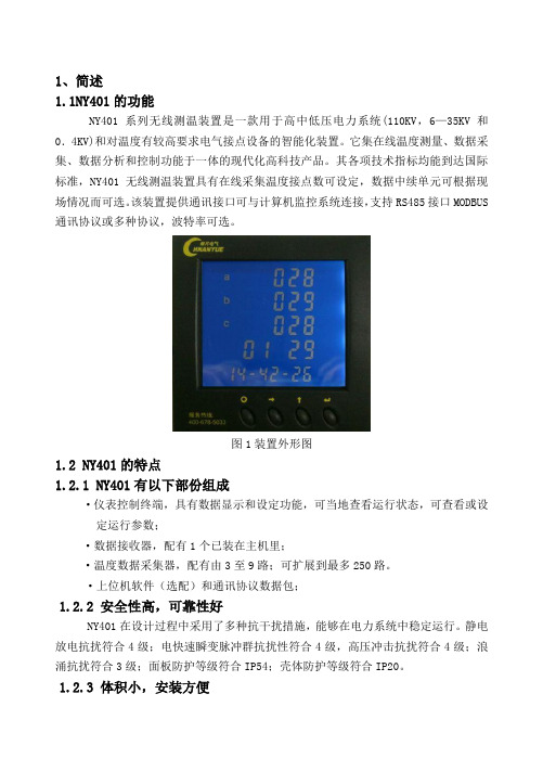
1、简述1.1NY401的功能NY401系列无线测温装置是一款用于高中低压电力系统(110KV,6—35KV和0.4KV)和对温度有较高要求电气接点设备的智能化装置。
它集在线温度测量、数据采集、数据分析和控制功能于一体的现代化高科技产品。
其各项技术指标均能到达国际标准,NY401无线测温装置具有在线采集温度接点数可设定,数据中续单元可根据现场情况而可选。
该装置提供通讯接口可与计算机监控系统连接,支持RS485接口MODBUS 通讯协议或多种协议,波特率可选。
图1装置外形图1.2 NY401的特点1.2.1 NY401有以下部份组成·仪表控制终端,具有数据显示和设定功能,可当地查看运行状态,可查看或设定运行参数;·数据接收器,配有1个已装在主机里;·温度数据采集器,配有由3至9路;可扩展到最多250路。
·上位机软件(选配)和通讯协议数据包;1.2.2 安全性高,可靠性好NY401在设计过程中采用了多种抗干扰措施,能够在电力系统中稳定运行。
静电放电抗扰符合4级;电快速瞬变脉冲群抗扰性符合4级,高压冲击抗扰符合4级;浪涌抗扰符合3级;面板防护等级符合IP54;壳体防护等级符合IP20。
1.2.3 体积小,安装方便NY401无线测温装置控制终端外形尺寸符合DIN96×96标准,壳体深度为78mm,采用自锁面板式安装机构,无需螺丝固定即可安装。
小巧的外形和简洁的安装方式使NY401的拆装非常方便;NY401温度数据采集器由捆绑式安装,无须打孔和使用安装工具,调试和安装非常方便。
1.2.4 系统接线方便灵活系统接线方式简单,人性化,不须有专业知识就可以安装。
1.2.5 显示直观、操作简便大尺寸专用液晶模块可以实时显示多项信息,配合明亮的背光,使操作者在光线差的情况下也能准确阅读数据。
操作方式人性化,操作者能在短时间内掌握,阅读数据和参数设置等操作将变得简单易行。
nRF24L01P产品说明书V1.0资料
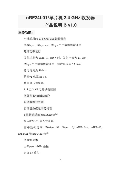
nRF24L01+单片机2.4 GHz收发器产品说明书v1.0主要功能:全球通用的2.4 GHz ISM波段操作250kbps, 1Mbps and 2Mbps空中数据传输速率超低功率运行发射功率为0dBm(1.0mW)时,发射电流为11.3mA2Mbps空中数据传输速率,接收电流为13.5mA掉电电流为900nA待机-I电流26μA片内电压调整器1.9至3.6V电源供电范围增强型ShockBurst TM自动数据包处理自动包数据包事务处理6数据通道的MultiCeiver TM与nRF24L01嵌入式兼容空中数据速率250kbps 和1Mbps,与nRF2401A,nRF2402, nRF24E1和nRF24E2兼容低BOM成本±60ppm 16MHz晶振容许5V输入紧凑的20引脚4x4mm QFN封装应用无线 PC外围设备鼠标,键盘和遥控器三和一桌面捆绑先进的媒体中心遥控器网络电话耳机游戏控制器蓝牙模块运动手表和传感器消费电子产品射频遥控器家庭和商业自动化超低功率无线传感器网络RFID 射频识别资产跟踪系统玩具免责条款北欧半导体ASA有权做出随时更改,提高产品可靠性、功能或设计,不另行通知。
北欧半导体ASA不承担由于应用程序或使用任何所述产品或电路引起的责任。
所有应用程序的信息咨询,不构成说明书的组成部分。
极限值超过一个或多个限制的应力可能会造成设备永久性损坏。
这些应力等级只有在这样或那样的操作环境中提出,在规范中没有给出。
长时间暴露在限制值附近可能会影响设备的可靠性。
生命支持应用这些产品并非为因故障会引起人身伤害的维生装备,设备或系统设计的。
北欧半导体ASA客户使用或出售这些产品,他们将自担风险并同意完全赔偿北欧半导体ASA因使用不当或销售行为造成任何损害。
详细联系方式访问www.nordicsemi.no进入北欧半导体销售办事处和全世界的分销商网站总办公室:Otto Nielsens vei 127004 Trondheim电话: +47 72 89 89 00传真: +47 72 89 89 89www.nordicsemi.no写作惯例本产品规范遵循一套排版规则,文档一致,容易阅读。
罗盈网络(Roving Networks)RN-41 RN-41-N类1蓝牙模块说明说明书

RN-41/RN-41-N Class 1 Bluetooth Module
RN-41-DS
Features
• Fully qualified Bluetooth® version 2.1 module, supports version 2.1 + Enhanced Data Rate (EDR)
> 140
115
Units
dBm dBm dBm dBm dBm dBm kHz kHz kHz kHz kHz kHz kHz kHz kHz kHz kHz kHz
Table 5. Digital I/O Characteristics
3.0 V ≤ VDD ≤ 3.3 V Input Logic Level Low Input Logic Level High Output Logic Level Low Output Logic Level High All I/O pins (Except reset) Default to Weak Pull Down
Typ.
-80 -80 -80 16.0 16.0 16.0 5 5 5 900 15 13 165 165 165 190 190 190
Max.
-86 -86 -86
Bluetooth Specification
≤ -70
≤ 20
75 75 75 1000 175 175 175 -
75
≤ 1000 40 20
RN-41
Rstal
CSR BlueCore-04 External
VCC GND GPIO4 GPIO5 GPIO6 USB UART PCM
Flash Memory
FS1120操作说明EP7F-200712

— 光电感烟探测器 JTY-GD/OP620、JTY-GD/OP820,感温探测器 JTW-ZD/HI620、JTW-ZD/HI820; — 手动火灾报警按钮 J-SJ-P-M/MT340、J-SJ-P-M/MT820,消火栓按钮 MT350、MT830; — 中继模块 DC1131-AA、DC1157-AA(3 路); — 输入/输出模块 DC1136-AA、DC1154-AA; — 专用输入输出模块 MB820。 l 在系统中除利用可编址输出模块控制现场消防设备外,还可以由控制器直接控制若干个输出设备。
第1页 共 46 页
FS1120 系列产品操作说明书(EP7)
一 系统概述
FS1120 系列产品包括: — FS1120 型火灾报警控制器(联动型) — FS1120R 型火灾报警控制器(联动型) — FS1120R门子西伯乐斯技术,整机采用组合式结构,软件和硬件都可以根据工程需 要进行组合。通过软件对现场进行编程,液晶显示器上显示的地址即为实际地址,从而使工作人员一目了然。 公司的各种产品都有标准配置,但是,如果工程需要,都可以进行多种功能扩展。例如:回路扩展、灭火扩 展、输入/输出扩展、网络扩展、火灾显示盘扩展等。
FS1120 系列产品操作说明书(EP7)
目录
一 系统概述 ..................................................................................................................................................2 二 操作盘概貌..............................................................
UFM 41移动过滤器单元的说明书

1. Intended useThe two versions of the mobile filter unit UFM 41 according ti the technical parameters of the data sheet 4006 are designed for the finefiltration of operating fluids with dirt particles 200 Micron. Larger particles may lead to premature wear of the gearpump.2. Commissioning The filter unit is supplied and delivered ready for operation: - The filter unit is not connected to the electric network. - The motor protection switch is shut off.-The suction and discharge hoses are wound up and the lances are in their respective locating tubes. - The unit is equiped with a filter elemet. - The draining and airbleeding screws and the filter lid are closed.-The filter housing holds roughly 5 l of operating fluid left over from the previous filter process. (It is recommended to mark a reference to the last filtered operating fluid on the filter unit). Before each commissioning the cleanliness of the lances, particulary that of the discharge hose, must be checked. Contaminated lances are to be cleanes with solvent before they are lowered into the fluid that is going to be filtered. The suction anddischargehoses are lowered into the respective tanks. During the operation of the filter unit the lance of the suction hose must be immersed in the fluid up to 50mm minimum. Make sure that the fluid that is to be filtered can easily enter and exit the lances of the hoses.Connect the filter unit the electric network (Note working voltage and kind of current!).The unit is turned on and off by means of the motor protection switch. After operating the unit or after maintenance and repair works the initial state has to be restored.3. Changing the element The filter element must be exchanged when the clogging indicator shows a pressure of 6 bar. For the exchanging of the element the filter unit has to be in initial state. The drain screw …E3“ and the airbleeding screws …E1“ are opened and the fluid left over in the filterunit is drained into the oil tray. The fluid gathered in the oil tray is to be treated as contaminated fluid. It is cleared from the oil tray by inclining the entire unit.When no more fluid emerges from the drain holes, the lid of the filter unit is opened and the filter element can be taken out, Dependingon the degree of contamination, the filter housing has to be cleaned before the new element can be inserted. The exchange element is taken out of ist wrapping just before it is inserted into the housing. The element must be checked on ist integrity (no visible mechanic damages) and ist completeness (O-ringes in the circular groove of the element). After insertion of the new filter element into the housing, the lid is put on and tightened by means of the locknut (torque: 60Nm). During the entire process of exchanging of the element particular attention has to be paid to preventing the contamination of either the filter element or the housing.Finally, the drain and aurbleeding screws are tightened.4. Cleaning the filter housingAfter the filtration of heavily contaminated fluid and when visible dirt particles are found in the filter housing, a thorough cleaning of thelatter becomes necessary. The housing is cleaned upon the exchange of the filter element. The drain screw …E3“ is opened. The inside of the housing is cleaned with conventional brushes and detergents.During the entire cleaning process make sure that no dirt particles get to the inside of the element (clean-oil side)(drill hole diameter 55of the locating peg) and that no solvent remains in the housing.5. Venting Generally, a separate airbleeding is not necessary. At a pressure of 6 bar the air blocked in the filter housing cannot dissolve into the fluid and is evacuated ba the discharge hose. In case a separate airbleeding connection is required ba the user, the filter unit is to be equired with a airbleeding unit according to data sheet no. 1650.Order reference of the airbleeding unit: - mini measurement connection MA.3.ST - high pressure hose M16.630 (length 630 mm) or- high pressure hose M16.2000 (length 2000 mm) - spray protection M166. General information - Every time the lid of the housing has been opened, the condition of the flat gasket 162x144x2 has to be checked. Damaged gaskets have to be replaced.- Torque of locknut: 60 Nm.- Filter units with mototr protection switch shut themselves off automatically after 5 min. of an operating pressure of 6 bar. EDV 10/95 - Englisch+49 (0)6205 2094-0 +49 (0)6205 2094-40 phone fax Friedensstrasse 41, 68804 Altlussheim, Germany e-mail url**************************/filtration。
FSN超声波处理器说明书

目录1、概述 (2)2、工作原理 (2)3、整机结构名称 (2)4、电气原理 (3)5、产品特点.......................................................................................................3-46、使用条件 (4)7、安装操作指南 (5)8、维护保养 (5)9、配套清单 (5)9、变幅杆更换...................................................................................................6-7上海生析超声仪器有限公司1、概述上海生析超声仪器有限公司是一家集研究、设计、生产、销售以及维修超声波设备的专业产家。
生析公司有着集十多年生产超声波设备经验,设计及生产多种规格超声设备,产品种类有台式超声波清洗器、工业超声波清洗、超声波细胞破碎仪、超声波乳化仪、超声波处理器、超声波塑料焊接机、超声波换能器等等。
其产品广泛应用于全国高等院校的实验室、光学工业、珠宝首饰、航天工业、五金工业、汽车制造工业。
生析超声仪器有限公司以先进雄厚的技术力量,不断开发新产品,“高技术、高品质、优质的售后服务” 是生析公司的宗旨。
它将为广大客户提供全面的超声设备与服务。
2、工作原理超声换能器震动时产生的超声波作用于液体时,液体中每个气泡的破裂会产生能量极大地冲击波,相当于瞬间产生几百度的高温和高达上千个大气压,这种现象被称为“空化效应”。
超声空化是强超声在液体媒质中引起的一种特有的物理过程,它伴随有许多奇妙的现象和惊人的效应。
空化基本效应表现为高温效应,放电效应,发光效应,以及冲击、压力效应等等。
人们正是利用这些独特的效应而广泛应用于医药、生物、化学、物理等领域。
3、整机结构名称前面板后面板①连接线缆②套筒③换能器④变幅杆⑤液晶控制器⑥仪器机箱⑦输出插座(连接换能器)⑧仪器铭牌⑨保险丝座⑩总电源插座(11)总电源开关(12)输入插座(连接温度探头)(13)过流保护指示4、电气原理1.发生器本发生器的原理方框示意图:超声电路结构2.换能器所采用的压力换能器是夹心单螺钉结构,不同型号和功率的换能器配用不同规格和数量的电压陶瓷片。
创新流动力低压过滤器41应用说明书

ApplicationsAgriculturalAutomotiveConstructionGearboxesIndustrialSteel / HeavyIndustryTechnical DetailsMounting Method 4 Mounting holes - filter housing Port Connections Inlet / Outlet30 60/110 160/240 330 660 950 1300½” NPT / 0.71” Dia Smooth SAE-12 / SAE-12SAE-20 / SAE-20SAE-20 / 2” NPT 2” NPT / 2” NPT2” SAE Flange, Code 61 / 2” NPT 3” SAE Flange, Code 61 / 3” NPT 3” SAE Flange, Code 61 / 3” SAE Flange, Code 613-1/2” SAE Flange, Code 61 / 3-1/2” SAE Flange, Code 614” SAE Flange, Code 61 / 4” SAE Flange, Code 61Direction of Flow Inlet: Side Outlet: bottom Materials of Construction3060-330 660-1300Housing Polyamide Aluminum Ductile IronLidPolyamide Aluminum Ductile IronFlow Capacity306011016024033066095013008 gpm (30 lpm)16 gpm (60 lpm)29 gpm (110 lpm)42 gpm (160 lpm)63 gpm (240 lpm)87 gpm (330 lpm)174 gpm (660 lpm)251 gpm (950 lpm)343 gpm (1300 lpm)Housing Pressure Rating Max. Oper. Press:Proof Pressure:Fatigue Pressure:360 psi (25 bar); (size 30 - 145 psi, 10 bar)217 psi (15 bar)145 psi (10 bar) @ 1 million cyclesBurst Pressure:3060/110160/240330660-1300580 psi (40 bar)1080 psi (75 bar)1230 psi (85 bar)1440 psi (100 bar)>1440 psi (100 bar)Element Collapse Pressure RatingBN/HC, W/HC,ECO/N, BN/AM, P/HC, AM V290 psid (20 bar)145 psid 10 bar) 3045 psid (210 bar)Fluid Temperature Range -22° to 250°F (-30° to 121°C)Fluid CompatabilityCompatible with all petroleum oils and synthetic fluids rated for use with Fluoroelastomer or Ethylene Propylene seals. Contact HYDAC for information on special housing and element constructions available for use with water glycols, oil/water emulsions, and HWBF.Indicator Trip PressureP = 29 psi (2 bar) -10% (standard)P = 72 psi (5 bar) -10% (optional)Bypass Valve Cracking PressureΔP = 43 psid (3 bar) +10% (standard)ΔP = 87 psid (6 bar) +10% (optional)FeaturesUÊRF 30 filters constructed of polyamide plastic.UÊ R F 60 - 330 filters constructed of aluminum material. Aluminum alloy is water tolerant - anodization is not required for high water based fluids (HWBF).UÊRF 660 - 1300 filters constructed of ductile iron.UÊ N on-welded housing design reduces stress concentrations and prevents fatigue failure.UÊ I nlet/outlet port options include NPT, SAE straight thread O-ring boss, and SAE 4-bolt flange to allow easy installation without costly adapters.UÊ O -ring seals are used to provide positive, reliable sealing. Choice of O-ring materials (Nitrile, Fluoroelastomer, EPDM) provides compatibility with petroleum oils, synthetic fluids, water-glycols, oil/water emulsions, and high water base fluids.UÊBolt-on lid requires minimal clearance for removal.UÊ R eusable contamination basket prevents loss of retained contaminants into the reservoir during element replacement.UÊ C logging indicators can be serviced without interruption of the hydraulic system.UÊ S ingle piece casting provides rigidity for inline or in-tank mounting.RF SeriesIn-tank / Inline FiltersÎÈäÊ«Ã ÊUÊÕ«ÊÌ Ê{ääÊ}« ÊC o u r t e s y o f C M A /F l o d y n e /H y d r a d y n e ŀ M o t i o n C o n t r o l ŀ H y d r a u l i c ŀ P n e u m a t i c ŀ E l e c t r i c a l ŀ M e c h a n i c a l ŀ (800) 426-5480 ŀ w w w .c m a f h .c o mModel CodeRF BN/HC 330 D L 10 H 1 . X / 16 - V - B6Filter TypeRF =Return Line FilterElement Media BN/HC = Betamicron ® (Low Collapse) ECO/N = ECOmicron ® (Low Collapse) AM = Aquamicron ® BN/AM = Betamicron ®/Aquamicron ®1 P/HC = Polyester W/HC = Wire Screen Size 30, 60, 110, 160, 240, 330, 660, 950, 1300Pressure Rating B = 145 psi (10 bar) (size 30 only) D = 360 psi (25 bar)Type of Connection B = 1/2” NPT (size 30) M = SAE 48 Flange (size 660)C = SAE 12 (sizes 60, 110) N = SAE 48 Flange Inlet / 3” NPT Outlet (size 660) E = SAE 20 (sizes 160 - 330) O = SAE 56 Flange (size 950) G = 2” NPT (size 330)P = SAE 64 Flange (size 1300)L = SAE 32 Flange Inlet / 2” NPT Outlet (size 330)Filtration Rating (micron) 3, 5, 10, 20 = BN/HC, ECO/N 10, 20 = P/HC 3, 10 = BN/AM25, 74, 149 = W/HC40 = AMType of Static or ΔP Clogging Indicator A, B/BM, C, D, HType Number 1 = Standard ConnectionModification Number (latest version always supplied) Inlet Port Configuration 3 = NPT (sizes 30 & 330) 12 = SAE Straight Thread Inlet/Outlet Connections (sizes 60, 110, 160, 240) 16 = SAE Flange Code 61 Inlet Connections (sizes 330 - 1300 only)Seals(omit) = Nitrile (NBR) (standard) V = Fluoroelastomer (FPM)EPR = Ethylene Propylene (EPDM)Bypass Valve (omit) = 43 psid (3 bar) (return line - standard) KB = No Bypass (flushing system) not available with ECO/NB6 = 87 psid (6 bar) (return line)B1 = 15 psid (1 bar) (lubrication or coolant applications) B0.2 =3 psid (0.20 bar) (suction line)SupplementarySO103H = Modification of BN4HC & W/HC Elements For Phosphate Ester Fluids L24, L48, L110, L220 = Lamp for D-type clogging indicator (LXX, XX = voltage) DE = ΔP Indicator (sizes 660, 950, 1300)Model Codes Containing RED are non-stock items — Minimum quantities may apply – Contact HYDAC for information and availabilityReplacement Element Model Code0330 R 010 BN4HC / VSize0030, 0060, 0110, 0160, 0240, 0330, 0660, 0950, 1300Filtration Rating (micron) 3, 5, 10, 20 = BN4HC, ECO/N 10, 20 = P/HC 3, 10 = BN/AM25, 74, 149 = W/HC 40 = AM Element MediaBN4HC, ECO/N, P/HC, BN/AM, W/HC, AM Supplementary Details (omit) = standard V = Fluoroelastomer (FPM) sealsClogging Indicator Model CodeVR 2 B . X / Indicator PrefixVR = Return Filters Trip Pressure 2 = 29 psid (2 bar) (return filters) 5 = 72 psid (5 bar) (optional)Type of Indicator A = no indicator, plugged port B/BM = Visual pop-up (auto/manual reset) C = Electric switch D = Electric switch and light H = Electric pressure switch Modification Number Supplementary Details Light Voltage (D type indicators only) L24 = 24V L110 = 110V Seals(omit) = Nitrile (NBR) (standard) V = Fluoroelastomer (FPM)(For additional details and options, see Clogging Indicators section.)NPT available w/Adapter C o u r t e s y o f C M A /F l o d y n e /H y d r a d y n e ŀ M o t i o n C o n t r o l ŀ H y d r a u l i c ŀ P n e u m a t i c ŀ E l e c t r i c a l ŀ M e c h a n i c a l ŀ (800) 426-5480 ŀ w w w .c m a f h .c o mDimensions shown are for general information and overall envelope size only. Weights listed are without element. For complete dimensions please contact HYDAC to request a certified print.RF 603.54”RF 1106.30”RF 1605.12”3.77”(96mm ) 4.96”(126mm )RF 2407.48”)))Clearance required)12.6”mm )OUTLETOUTLETOUTLETOUTLETOUTLETG 1/2RF95013.78”mm )RF130018.11”mm )))Clearance required Clearance required for element removal)Dimensions RF 30RF 60 - 240RF 330Mounting PatternRF 660RF 950 - 1300C o u r t e s y o f C M A /F l o d y n e /H y d r a d y n e ŀ M o t i o n C o n t r o l ŀ H y d r a u l i c ŀ P n e u m a t i c ŀ E l e c t r i c a l ŀ M e c h a n i c a l ŀ (800) 426-5480 ŀ w w w .c m a f h .c o mRF 30 HOUSINGQ in gpmQ in l/min052520151001.61.20.80.412345678051015202530Sizing InformationTotal pressure loss through the filter is as follows:Assembly P = Housing P + Element P Housing Curve:Pressure loss through housing is as follows:Housing P = Housing Curve P xActual Specific Gravity0.86Adjustments must be made for viscosity & specific gravity of the fluid to be used! (see sizing section on page 19)Element K FactorsΔP Elements = Elements (K) Flow Factor x Flow Rate (gpm) x Actual Viscosity (SUS) x Actual Specific Gravity(From Tables Below)141 SUS 0.86All Element K Factors in psi / gpm.C o u r t e s y o f C M A /F l o d y n e /H y d r a d y n e ŀ M o t i o n C o n t r o l ŀ H y d r a u l i c ŀ P n e u m a t i c ŀ E l e c t r i c a l ŀ M e c h a n i c a l ŀ (800) 426-5480 ŀ w w w .c m a f h .c o m。
fsn41n参数设置说明书
fsn41n参数设置说明书参数设置说明书:FSN41N1.介绍FSN41N是一款高性能的网络参数设置工具,用于配置网络设备的各种参数。
通过使用FSN41N,用户可以轻松地管理和设置网络设备的各项参数,提高网络设备的运行效率和性能。
2.安装在安装FSN41N之前,请确保系统满足以下要求:- 操作系统:Windows 7及以上版本-硬件要求:4GBRAM,100GB可用存储空间按照下列步骤安装FSN41N:2)双击安装程序,按照提示进行安装3)安装完成后,启动FSN41N,开始设置参数。
3.主要功能FSN41N具有以下主要功能:-设置网络连接:用户可以设置设备的IP地址、子网掩码、网关等基本网络连接参数。
-配置无线网络:用户可以设置无线网络的名称、加密方式、密码等参数。
-管理设备访问:用户可以设置设备的访问权限,包括用户名称、密码、权限级别等。
-配置路由器:用户可以设置路由器的路由表、NAT、端口映射等参数。
4.使用指南在使用FSN41N进行参数设置之前,请确保已连接到网络设备。
按照以下步骤进行参数设置:1)运行FSN41N应用程序。
2)在菜单栏中选择所需的参数设置选项,如网络连接、无线网络等。
3)输入相关参数,如IP地址、密码等。
4)点击保存按钮,保存设置。
5)完成参数设置后,重新启动设备以使设置生效。
5.注意事项在使用FSN41N进行参数设置时,请注意以下事项:-仔细检查输入的参数是否正确,特别是IP地址、子网掩码等网络连接参数。
-在设置路由器等涉及网络连接的参数时,确保了解设备的工作原理和网络拓扑。
-避免在网络繁忙时进行参数设置,以免影响网络设备的正常工作。
-在参数设置完成后,确保重新启动设备以使设置生效。
6.常见问题解答-Q:我在参数设置过程中遇到错误提示,该怎么办?A:首先,检查输入的参数是否正确。
如果错误提示仍然存在,请尝试重新启动设备和应用程序,并重新进行参数设置。
-Q:我忘记了设备的登录密码,该怎么办?A:在设备上通常有一个恢复出厂设置按钮,按下该按钮可以将设备恢复为出厂默认设置,包括登录密码。
- 1、下载文档前请自行甄别文档内容的完整性,平台不提供额外的编辑、内容补充、找答案等附加服务。
- 2、"仅部分预览"的文档,不可在线预览部分如存在完整性等问题,可反馈申请退款(可完整预览的文档不适用该条件!)。
- 3、如文档侵犯您的权益,请联系客服反馈,我们会尽快为您处理(人工客服工作时间:9:00-18:30)。
FS—N41p说明书
1、光纤放大器的调试方法和过程:
(1)SET键,此按钮可用于敏感度设定。
本传感器的基本原理为:通过光纤探头对不同介质折射率的感应,从而获得数字信号,显示在屏幕上,通过显示数值的大小与设定灵敏值的比较发送开关量。
(2)指示灯,此灯在传感器有信号输出时发生亮灭变化。
(3)“设定灵敏值”,在屏幕上显示为绿色,表明当前设定的灵敏值。
当探头采集到的数值变化至此数值时,传感器产生信号。
(4)“当前灵敏值”,在屏幕上显示为红色,显示传感器当前采集的数值。
(5)“选择按钮”,及左右箭头,可以实现各种功能的选择,相当于翻页键。
(6)“模式选择按钮”,此按钮可用于设定不同的工作模式。
2、接线方法。
3、灵敏度校准。
(1)全自动校准:在工件进入探头的灵敏区域时,按住“SET”键不放,保持3秒,灵敏值将会被设定,显示为绿色(2)两点校准:在工件未进入灵敏区域时,按住“SET”键保持三秒,有一个敏感值被记忆,然后将工件放置在敏感区域,按下“SET”键保持三秒,另一个敏感值被记忆,当敏感值从一个值变化为另一值时,传感器产生电平变化。
(3)一般校准:也可以通过按“选择按钮”,及左右键来增减敏感度的设定值。
(4)位置校准:在工件未进入灵敏区域时,按住“SET”键保持三秒,然后将工件放置在离探头一定距离,按下“SET”键保持三秒,一个敏感值被记忆,当工件每次到达此位置时,传感器产生电平变化。
4、常开常闭设定。
按下最右侧的开关选择按钮,可以选择,内部开关为常闭还是常开。