RM立磨壳体带耐磨衬板和手动调整喷环
TRM型立磨介绍
6、小型矿渣球磨,产量10~30t/h,耗电:约56kwh/t
矿渣粉磨工艺对比
系统
主机设备 可烘干水分,% 粉磨电耗,kWh/t 系统工艺 10 80 简单 10 47 复杂 20 38 简单
Pfeiffer FLS
Polysius UBE 天津院 合肥院 沈重
2.TRM 型立磨研发及发展现状
• 1978年开始与吴江水泥厂合作开始,近30年: 87台套 (2003年 以前10台,至2005年9台,2006年-现在:68台) • 生料:1000TPD~5500TPD 配套水泥熟料配套立磨TRM25.5, TRM31.31, TRM36.41, TRM38.41, TRM40.41, TRM45.41, TRM53.41 • 矿渣磨:30TPY ~ 90TPY TRMS31.31, TRMS40.41, TRMS45.41 • 煤立磨: 1000TPD~5500TPD 配套水泥熟料配套立磨 TRMC20.2,TRM20.3, TRMC23.3, TRMC25.2, TRMC36.4 (TRMC36.41 为越南幸福水泥提供 大型无烟煤立磨) • 电厂脱硫用石灰石立磨:TRM16.3, TRM20.3, TRM22.3 • 水泥终粉磨:TRMK45.41-100WTY--台湾幸福水泥签订3台
辊磨
缺点:单机成本高,操作相对复杂
3.3, 影响立磨性能的要素 水泥原料与粉磨有关的基本性能包括物料粒度、 易磨性、 磨蚀性和水分等。 (1).易磨性:Wi --- 邦德功指数(中等:10-11kwh/t)by 球磨 MF --- 辊磨易磨性指数(中等: 0.9-1.0)by 立磨 对煤磨:HGI---哈氏指数(中等:55)by 哈氏仪 (2).磨蚀性:WF --- 磨蚀性指数: 影响磨辊辊套和衬板及选粉机叶片 的寿命 (3).水分: 直接关系到粉磨设备的烘干能力和热源,五级 预热器的尾气最大可烘干7%的水分。否则要 加热风炉或引入循环热风。
LGMS矿渣立磨设计说明 (NXPowerLite)

3.5主辊装置(ROLLERS)
了LGM系列机型,即平盘锥辊、曲臂加载,矿渣立磨采用主辅辊碾 压。
立磨开发情况介绍
• 课题组进行了立磨热力系统计算、设备选型计算、主参数计算、
选粉机计算研究等。对复合辊套、高铬铸铁衬板进行了设计、工 艺研究并进行了工艺试验,已成功用于产品,耐磨性能达到较高 水平。已掌握了立磨的设计和制造技术。
• 2006年依托江苏磊达水泥公司矿渣粉磨线,进行了LGMS4624矿渣
LGMS4624水泥矿渣立磨技术参数
生产能力 磨盘直径 磨辊数量 磨辊直径(中径) 主辊 辅辊 磨辊宽度 磨盘转速 磨辊最大辊压力 80-90 t/h(矿渣) 4600 mm 2+2 2400 mm 1600 mm 690 mm 24.27 r/min 2100kN
选粉机 高效动静态选粉机 电机功率 250 kW 输出转速 50-175 r/min(变频调速) 选粉机减速机型号 Flender 输入转速 1480 r/min 输出转速 50-175 r/min 入磨风量 压力 磨辊密封风量 风压 194016 Nm3/h(2590C) -0.5kPa 5000 Nm3/h 5.5kPa
物料出口
选粉机
主辊
物料入口 减速机
辅辊 热风入口 磨盘 排渣口
3.2磨机支座
铸 焊 接 构 , 带基 础架 和基础螺栓及减速机 底板。整体铸造的曲 臂摆动轴承座,与焊 接结构的支架焊接而 成。两个气体进口的 风管及风环与支架采 用螺栓连接并焊接在 一起。在一侧气体入 口下设有粗料卸料 口,用于将粉磨时从 喷气环落下的粗粉排 出,排料口处帖耐磨 衬板。
立磨参数的控制及操作

立磨参数的控制及操作一、立磨参数的控制1磨机通风(1)风量控制①出磨气体中的含尘(成品)浓度应在550~800m3之间。
②出磨管道风速一般要大于20m∕s,避免水平布置。
③喷嘴环处的标准风速为90m∕s o④当物料的易磨性不好,磨机的产量低,喷嘴环风速较低时,根据需要用铁板挡上磨混后喷嘴环的风孔,减少通风面积,增加风速。
挡多少个孔,要通过平衡计算确定。
⑤根据具体情况通风量可在70%-105%范围内调整,但窑磨串联的系统应不影响窑系统的操作。
(2)风温的控制①生料磨出磨风温不许超过120o C z否则软连接受损,旋风筒分格轮可能膨胀卡停,磨机容易产生振动;煤磨出磨风温视煤质情况而定,挥发分高则出磨风温要低,反之可以高些。
一般控制在100。
C以下,以免发生燃烧、爆炸等现象。
②烘磨时入口风温不能超过20(ΓC,以免使磨辑内润滑油变质。
(3)系统漏风系统漏风是指立磨本体及出磨管道、收尘器等处的漏风。
在总风量确定的情况下,系统漏风会使喷嘴环处的风速降低,导致吐渣严重。
出口风速降低,使成品的排出量减少,循环负荷增加,压差升高,总风量减少,易造成饱磨、振动停车,还会降低产量,造成结露。
如果为了保持喷嘴环处的风速,而增加通风量,将会增加风机和收尘器的负荷,浪费能源。
同时也受风机能力和收尘器能力的限制。
德方认为MPS立式磨系统漏风要低于4%,根据我国国情,应按低于10%漏风进行风路设计。
2、拉紧力拉紧力的选用与物料特性及磨盘料层厚度有关,因为立磨是料床粉碎,挤压力通过颗粒间互相传递,当超过物料的强度时被挤压破碎,挤压力越大破碎程度越高,因此,越坚硬的物料所需拉紧力越大。
在其他因素不变的情况下,液压装置的拉紧力越大,作用于料床上物料的正压力越大,粉碎效果就越好。
但拉紧力过高会增加引起振动的概率,电动机电流也会相应增加。
因此操作人员要根据物料的易磨性、产量和细度指标以及料床形成情况和控制厚度及振动情况等统筹考虑拉紧力的设定值。
MLS3726立式辊磨机使用说明书

目录1.机器的用途2.技术参数3.磨机的工作原理及结构4.磨机的操作5.磨机的安装6.磨机的调整和试运转7.磨机的故障排除、维修及润滑8.滚动轴承目录9.易损件目录1 机器的用途MLS3726立式辊磨机用于粉磨水泥生料及其它建筑、化工、陶瓷等工业原料。
2 技术参数2.1主机技术参数研磨轨道中心名义直径3750mm生产能力250t/h(根据物料易磨性实验所得)入磨物料粒度<95mm入磨物料最大含水量<12%可磨性7.8kWh/t出磨生料细度<12%R0.08mm磨盘工作转速23r/min磨盘慢转速0.525r/min主电动机型号YRKK800-6功率2500KW转速994r/min辅助电机功率90KW转速990r/min磨内喷水量(三个喷头共计)<4m3/h(实际喷水量由工艺决定)喷水压力 0.3MPa喷水温度 <25℃机器总重量 450t(不包括主电机、主减速机及其润滑站)2.2各部分技术性能2.2.1 磨辊组磨辊数量 3个磨辊直径 2650mm磨辊宽度 900mm磨辊研磨力(一个磨辊) 1500kN2.2.2 张紧装置张紧液压缸(带蓄能器) 3组油缸结构形式双作用缸蓄能器充氮气预压力 0.33~0.66P1MPa油缸工作压力 P1<20MPa(实际值按现场设定值)液压站电机功率 11kW转速 1450r/min加热器功率 2×1kW2.2.3主减速器输入轴转速 994r/min输出轴转速 994r/min液压站低压泵电机功率 2×15kW转速 1460r/min液压站高压泵电机功率 4×15kW转速 990r/min油加热器功率 6×6kW冷却器冷却水量 30m3/h冷却水压力 0.4MPa冷却水温度 <28℃2.2.4分离器叶片数量 108(动态叶片)调速范围 9~90r/min电机型号 YP2280M-4功率 90kW变频范围 3~100Hz减速器传动比 18冷却风机型号 G280-A功率 370W转速 1400r/min2.2.5密封空气风机风机型号 MF10-19-13No6.2A风机右旋90度转速 2940r/min风量 3000m3/h风压 8000Pa电机功率 30Kw2.2.6超越离合器气缸用风量少许(动作时用)风压 0.3MPa2.2.7辅助减速器输入轴转速 990r/min名义传动比 45传至磨盘转速 0.525r/min3.磨机的工作原理及结构3.1 工作原理磨机的磨辊靠张紧系统拉紧,分离器靠变频调速电机驱动,并可无极变速。
HRMA原料立式磨解读

5.3.3导风叶片
导风叶片是通过螺栓拧在壳体上的。 5.3.4传动装置 分离器的传动装置是由电动机、减速机、 联轴器等组成。减速机支撑在传动底座上, 减速机的出轴通过联轴器与转子主轴相连, 从而带动笼形转子的旋转。转子的转向从上 往下看为顺时针旋转。电动机采用变频调速, 通过调节转速达到对产品细度的控制。
结构见下图
二、主要部件的结构形式及技术特点
1.传动装置: 立式磨的传动装置由主电机、膜片联轴器、减速机、主 电机底座、减速机底座、辅助传动装置、导轨等部份组 成,安装在磨机下部,既要带动磨盘传动,还要承受磨 盘、物料、磨辊的重量以及加压装置施加的碾磨压力, 是立式磨中最重要的部件之一。润滑系统采用独立的油 站,并有油压、油温的自动保护系统,使全套装置工作 安全可靠。该型式的减速机具有体积小、重量轻、减速 比大、传动效率高等优点。减速机底座用来承载减速机。 辅助传动装置在磨机正常运转过程中是脱开的,只有在 磨机维修的时候才会用到。
成品物料的细度取决于导风叶片的角度 以及转子速度的调节。将导风叶片的角度加 大或者提高转子的速度,选粉后,物料的细 度更细;反之,将导风叶片的角度减小或者 降低转子的速度,物料的颗粒将会变粗。 总之,要想生产出合格的细度的产品, 必须在磨机的调试中逐步进行摸索。转子的 旋转方向取决于导风叶片的切向流方向,转 子的旋转方向和导风叶片的导风流方向是相 同的。 该分离器的分级效率高,调节余地大。
概
述
HRM3700E立式磨是合肥中亚建材装备有限责任公司 荣誉产品。是为曰产3200吨水泥熟料生产线配套设 计的大型原料立式磨。
HRM3700E立式磨是一种技术性能优异的烘干兼粉磨 设备,主要用于水泥生料的粉磨。该型立式磨具有 粉磨效率高、电耗低、入料粒度大、产品细度易于 调节、设备工艺流程简单、占地面积小、噪音低、 扬尘小、使用维护简单、运行费用低、耐磨材料消 耗少等优点。除此之外,该型立式磨还具有如下独 特性能:
立磨说明书
3.2.2磨辊
本磨机配备四个磨辊,互成90°角排列,通过胀套安装在摇臂上。磨辊由辊轴、轮毂、辊套、压圈、轴承及密封部件等组成。
轮毂通过双列圆柱滚子和双列圆锥滚子轴承安装在辊轴上,轴承采用稀油润滑、具有独立的油泵供油和回油系统,并可保证磨辊内润滑油的最低油位。辊套通过压圈固定于轮毂上,它由耐磨材料整体铸造,也可在表面堆焊耐磨合金。
1.11具有很高的运转率。
1.12单位能耗低。
1.13采用组合选份工艺过程,直接打碎已粉碎颗粒的团块,粉磨效率高。
1.14调节方便。
2、技术参数
2.1主要技术参数:
磨机名称 VRMR306.4立式原料磨
生产能力 190-220t/h
入磨物料粒度 <70mm(90以上)
转速 995r/min
电压 10KV
2.5主减速机
型号 MLX200F
输入轴转速 885r/min
速出轴转速 30.8r/min
减速比 32.24
2.6 主减速机稀油站
型号 GDR-L40x4/500
高压公称流量 4X40L/min
高压压力 21Mpa
3.2.10喷水装置
本磨机的喷水系统设有一个进水管,麽内设有环形水管并配有出水口,其对于稳定料层、减少震动起着十分重要的作用。
3.2.11润滑装置
本磨机的选粉机、摇臂装置采用集成干油润滑系统、主减速机、磨辊采用稀油润滑系统润滑。
4.磨机的安装
现场到货的所有部件必须根据不同情况妥善保管。机加工部件如减速机、运转部件与轴承配合件的必须保存在专用仓库内。
立磨磨辊、磨盘衬板磨损的现场修复

立磨磨辊、磨盘衬板磨损的现场修复立磨是一种理想的大型粉磨设备,广泛应用于水泥、电力、冶金、化工、非金属矿等行业。
它集破碎、干燥、粉磨、分级输送于一体,生产效率高,可将块状、颗粒状及粉状原料磨成所要求的粉状物料。
一、立磨使用中易出现的问题及危害分析Array1、易出现的问题●辊皮外表面磨损●辊皮裂纹或断裂●磨辊本体磨损●夹板螺栓断裂●磨辊轴承室磨损●减速机渗漏(漏油)2、危害分析…二、解决方案综上所述,水泥企业连续化生产特征明显,对于单一、重要设备更应该积极从本质上对各类问题寻求更多有效的解决方案,做到有备无患,将设备管理及维护的主动权掌握在企业手中,不断提高设备管理水平,为企业持续健康的发展奠定更稳固的基础。
问题1: 磨辊本体磨损解决方案:福世蓝系列聚合物复合材料现场修复 --- 2211F高分子金属复合修复材料方案优势:修复时间短、费用低、无热应力、实现辊皮与本体的最大配合,从而延长设备的使用周期。
部分合作单位:天瑞集团汝州有限公司(2500T/d生产线)、天瑞集团郑州有限公司(12000T/d 生产线)、中联集团东华水泥有限公司(5000T/d 生产线)、南阳中联分公司、华新(黄石)水泥有限公司(5000T/d生产线)等。
部分案例介绍:2010年 5 月份,某大型水泥集团分公司来电咨询我司关于史密斯立磨磨辊的修复,其磨辊辊体与辊皮存在间隙 0.7mm-1mm,严重影响生产。
经双方商讨达成合作共识,定于 6月 25 日检修时间修复。
2010年 6月5 日,我司突然接到该公司电话,称立磨磨辊其中一块辊皮由于磨损严重脱落(磨损尺寸:20mm),导致意外停机,企业决定提前检修。
我司技术人员前往指导修复,于6月 11 日修复完毕(因部分夹板螺栓变形难以取出,延长了修复时间),共计修复3个磨辊(36 块辊皮配合面)。
其技术服务得到企业领导好评。
注:具体操作细节请咨询淄博福世蓝高分子复合材料技术有限公司问题2:立磨减速机结合面漏油解决方案:1、使用福世蓝系列---25551高分子复合修复材料配合3223橡胶复合材料现场免停机治理;2、治理完毕后,将福世蓝--赛莫特纳米粒子陶瓷调节剂添加至润滑油。
原料磨更换辊套、辊心、轴承及衬板步骤
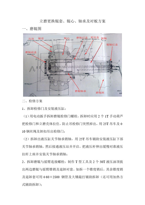
立磨更换辊套、辊心、轴承及衬板方案一、磨辊图二、检修方案1、拆卸检修门及安装液压缸:(1)用电动扳手拆卸磨辊检修门螺栓,拆卸时应用2个1T手动葫芦把检修门和立磨壳体拉住,防止吊检修门突然掉出,用25T吊车及φ10钢丝绳及卸扣吊出检修门;(2)拆卸出液压缸关节轴承销轴,用25T吊车辅助安装液压缸下部关节轴承销轴,然后接通液压站并开启,把液压杆伸出缓慢对准液压拉杆上座并安装关节轴承销轴;2、拆卸磨辊与摇臂连接螺栓:制作T型工具及2个50T液压油顶拔出两边磨辊与摇臂锥销及退卸衬套。
如拆一个锥度销后,其余锥度销及退卸套可用φ60×2500钢管及大锤敲打辅助拆卸(还可用加热方式辅助拆卸);3、翻出辊:通过移动液压站把对角两个磨辊翻出磨机外面,注意控制翻辊速度,防止速度过快把液压缸损坏;4、拆卸压块、辊套与辊心连接螺栓:用100割枪把辊套与辊心连接螺栓割断,制作T型工具及2个50T螺旋顶,用大锤敲击,吊车辅助拆卸辊套压块,辊套压块拆卸前应做好顺序记号,防止安装顺序混乱,螺栓孔对不上;5、安装磨辊拆卸工具:搭好脚手架,用30mm钢板制作一个辊套拆卸平台并直接焊接到磨辊两侧密封槽上,拆卸平台与辊套距离应与100T油顶高度一致,在地面用一根φ120的钢管直接支撑平台底部;6、顶出辊套:安装两台100T油顶到拆卸平台与辊套之间,开动油顶油站,加压约120MPa时,辊套则可拆卸出来,如不行,可用加热方式对辊套进行加热。
拆卸完毕,制作4个辊套吊勾(注:吊勾内侧弧度应与辊套表面弧度一致),用25T吊车吊下磨损辊套(约4T);7、拆卸、安装辊心及轴承:(1)拆卸磨辊轴与辊座后端盖,拆卸磨辊前端盖、轴承内圈压盖及辊心内部润滑油管;(2)安装2台50T薄油顶于拆卸平台,把辊心、轴承及磨辊轴整体从磨辊座里面拔出,用25T吊车吊下;(3)解体辊心、轴承及磨辊轴:拆卸辊心两端轴承外圈压盖,垂直吊起磨辊轴,则可分离辊轴带轴承与辊心(轴承与辊心是间隙配合),然后制作工具及油顶拔出磨辊轴承;(4)组装辊心、轴承及磨辊轴:清洗磨辊轴干净,然后把两套磨辊轴承安装到磨辊轴上;把辊心外轴承外圈端盖安装到辊心上,把辊心水平摆放,垂直吊起磨辊轴带轴承放入辊心里面,然后安装内轴承外圈端盖。
- 1、下载文档前请自行甄别文档内容的完整性,平台不提供额外的编辑、内容补充、找答案等附加服务。
- 2、"仅部分预览"的文档,不可在线预览部分如存在完整性等问题,可反馈申请退款(可完整预览的文档不适用该条件!)。
- 3、如文档侵犯您的权益,请联系客服反馈,我们会尽快为您处理(人工客服工作时间:9:00-18:30)。
Housing for the RM roller millwith wear protectionand manually adjustable nozzle ringCode wordOrder numberAAT-ItemContents1Technical Data ......................................................................................1-12Safety ..........................................................................................................2-13Components and description of functionning ...............................3-13.1Components ................................................................................................3-24Transport and assembly ....................................................................4-14.1Transport and storage instructions ..............................................4-14.2Assembly .....................................................................................................4-15Lubrication ...................................................................................................5-16Preparation for the test run .............................................................6-16.1Checks prior to the test run ............................................................6-16.2Setting and adjustment ......................................................................6-27Maintenance ................................................................................................7-17.1Inspection ....................................................................................................7-17.2Servicing ...............................................................................................7-37.3Troubleshooting ....................................................................................7-57.4Repair ..........................................................................................................7-58Spare parts ..................................................................................................8-19Appendix .....................................................................................................9-19.1Technical drawings ...............................................................................9-1EN22421.003A1 Technical DataNOTEInformation concerning the electrical equipment is contained in the separate electrical documentation or in the subsuppliers’ documentation..Information on the intended useSee machine manual of the RM roller millRMBasic dataYear of manufactureAltitudeNominal diameterWeight of the heaviest componentEN22421.003A2 SafetyNOTEBe sure to comply with the general safety instructions in the supplementImportant notes on the documentation.Use• The housing is part of a roller mill.Be sure to comply with the information concerning the intended use of the machine in the section Technical data .• Any use other than the intended use is forbidden. POLYSIUS AG is notresponsible for any damage resulting from any other than the intended use of the machine. All other use is at the owner’s own risk.POLYSIUS AG •The intended use also includes observance of instructions in the machine manual and the conditions for maintenance.Transport and assembly•All transportation instructions in this machine manual refer exclusively to transportation of the machine at the plant site. •Only use suitable hoisting gears and load-carrying equipment which is suitable and technically serviceable and has a sufficient load bearing capacity. • Never work under a suspended load.Operation• Any safety checks before or during operation depend on the relevant nationalregulations. The plant management is responsible for the performance and recording of such safety checks..•If changes in the machine or its operating behaviour relevant to safety occur,shut down the machine immediately.EN22421.003AMaintenance•Please observe also the safety instructions concerning the roller mill. • Ensure that for the entire duration of the maintenance work, all machines andmotors whose operation might endanger persons or equipment are switched off and safeguarded against restarting.• Ensure that all rotating parts of the machine have come to a standstill before you remove protection devices or open covers.• Before work is performed on the machine, ensure that there is no danger that persons touching the machine will burn themselves. Ensure that there is no hot material inside the machine when inspection and maintenance covers are opened.• Keep the machine free from oily and combustible materials. Never usegasoline or other easily inflammable substances for cleaning the machine.• Switch off the power supply to the electrical components before commencing any maintenance work.• After all maintenance work, check that there are no leaks in connecting points and connections.• Strictly observe the welding instructions when performing any welding work.•Never situate the source of the welding current in a confined space where walls have conductive properties. Only use 24–Volt lamps for illuminating the interior.24–Volt• If you carry out electrical welding on any part of the machine, never conductthe welding current through plain or antifriction bearings, other movable connections or measuring devices. Always directly connect the welding current return lead to the part being welded.•Remount all protection devices when maintenance work has been finished.Make absolutely sure that no persons are inside the plant component before you properly close the inspection and maintenance covers.EN22421.003A3 Components and description of functionningThe housing of the roller mill is designed in two parts.For inspection, maintenance and assembly work, the upper housing section isprovided with great doors.The areas of the housing which are particularly subjected to wear are protectedby exchangeable wearing plates.The hot gas channel around the inside of the lower section of the housing servesfor a uniform distribution of drying gas. The nozzle ring is designed for guiding thehot gas stream in the upper housing section. The seal between the lower housingsection and the grinding table is designed as a sliding contact seal.In the area of the tie rod passage a self-adjusting seal prevents any leakage ofmaterial being ground.The feed chute is protected by exchangeable wearing plates.The nozzle ring is the …bottleneck… in the roller mill. Here, the gas stream emergesat a high velocity, takes up the crushed material falling off the grinding table andcarries it upwards to the separator.3.1 ComponentsNOTESome details of the drawings in this manual may not be identical with the dra-wings supplied under the contract as listed in the section 9.1 Technical drawings.The housing consists inter alia of the•lower housing section •upper housing section with the doors •hot gas connection• nozzle ringEN22421.003AItems shown in the drawing of the housing2Hot gas connection 5Material guide plate 8Guide bracket 8.1Wearing plates for the guide bracket 9Nozzle ring 10Upper housing section 11DoorFigure 1 1Figure 2 c =guide pin of the roller pair unitEN22421.003AItems shown in the drawing of the housing1Lower housing section 2Hot gas connection 3Discharge device 3.1Wearing ring, below 3.2Wearing ring 3.3Cone lining 3.4Scraper reclaimer 3.5Driver plate 4Discharge connection for material recirculating by bucket elevator 4.1Wear protection for discharge connection 6Seal for the grinding table 7Wear protection in the lower housing section 9Nozzle ring 10Upper housing section 11Door 12Wearing plate in the upper housing section 14Seal for the tie rod assembly 15Terminal box for the confining air pipe 15.1Inspection cover b Grinding tableFigure 3 3EN22421.003AItems shown in the drawing of the nozzle ring (9)9.1Nozzle ring adjusting device 9.2Adjustable segment of nozzle ring 9.3Nozzle ring segment (internal)Figure 4 4EN22421.003A4Transport and assembly 4.1 Transport and storage instructionsThe machine is transported in single parts or in sub–assemblies. Make absolutelysure that suitable lifting equipment is employed in removing the parts from thetransport vehicles and transferring to the storage area.When they arrive at the site, all parts must be inspected for transport damage andplaced on wooden beams with the provision of suitable protection against moisture,contamination and damage. Never store the parts directly on the ground.4.2 AssemblyGeneral informationThe following assembly instructions do not detail the individual steps forassembling the units, but rather give an overview of the work to be performed.Differences in the design of the plants may lead to deviations from these assemblyinstructions.NOTEIt is a prerequisite of our warranty that final assembly and assembly inspection areundertaken by an assembly specialist from POLYSIUS AG.POLYSIUS AGWe recommend that an assembly specialist from POLYSIUS AG supervises thework from start to finish.POLYSIUS AGCareful selection of tools and appliances used and of the personnel is important forthe correct execution of the assembly work.CAUTIONIf electrical welding is carried out in any place of the machine, weldingcurrent must never be conducted through friction and antifriction bearings,other movable connections or measuring equipment to prevent damage to such parts.Always directly connect the welding current return lead to the part being welded.EN22421.003AMeasuring workElevation reference pointThe point of reference of all measuring work is the elevation reference pointauthoritative for the whole plant, which is fixed in relation to the zero datum linestated in the general arrangement drawing. The companies responsible forconstruction of the foundations and buildings determine the elevation referencepoint and inform our erection superintendent accordingly.To facilitate the measurements of axis and elevation for the erection of themachinery parts, the level of e.g. 1000 mm above zero datum line is marked on thefoundations of the mill and drive unit. For this purpose, steel plates of 200 x 200mm size were anchored in the foundation by the building contractor. Into theseplates, the elevation determined by means of a levelling instrument or a rubbertube level is permanently chiselled.Figure 5 5A=Datum mark B=Steel plate C=Anchorage D=Concrete E =Drilled hole for nailed connection to formworkTightening torque for boltsIf not stated otherwise in the drawings, the following specifications apply:•The tightening torque is applicable for bolts according to DIN EN 24014 and DIN EN 24017 of quality grade 8.8 • Threads and contact surfaces must be cleanAbbreviationsSWWidth across flats in mm mm MaTightening torque in Nm Nm Fv Pretensioning force in kN (for hydraulic pretensioning unit)KN dry = 0,15oiled = 0,13bolts SW Ma FvMa Fv M 16M 16 x 1,5242420321261.864.618219363.068.2M 20M 20 x 2303039541096.299.936037099.8102.5M 24M 24 x 2M 24 x 1,5363636690730750140.1148.2152.3620660680143.2152.4157.0M 30M 30 x 2464614001500228.4244.712501350232.2250.7M 36M 36 x 3555524002500327.3340.921502250334.0349.5M 42M 42 x 3656538004000445.1468.634503600460.5480.6M 48M 48 x 3757557006100585.2626.352005500608.5643.7M 56M 56 x 4858592009600812.2847.583008600835.8866.0M 64M 64 x 4959514000147001084.11157.912500130001104.61148.8M 72 x 6M 72 x 410510520000210001384.41453.718000190001423.61502.7M 80 x 6M 80 x 411511528000290001752.31814.925000260001789.31860.9EN22421.003AM 90 x 6M 90 x 413013041000420002291.32347.136000375002302.92398.9M 100 x 6M 100 x 414514556000590002826.93011.450000520002891.43007.1Assembly of the housing-Check the mill foundations for dimensional accuracy according to the generalarrangement drawing and the construction drawing.-Mark the longitudinal and transverse axes on the mill foundations and the steelstructure of the building. Prepare a measurement record!-Place the lower housing section (1) upon the foundation.-Mount the wearing rings (3.1 and 3.2) and the cone lining (3.3).-Attach the discharge device (3) to the grinding table (b).-Align the lower housing section (1) and bolt together. The distance (arrow)between the discharge device (3) and the wearing rings (3.1 and 3.2) must bethe same over the entire circumference.Figure 6-Mount the seal (6) onto the grinding table (b).-Mount the nozzle ring (9). The clearance to the grinding table must be the sameover the entire circumference and must in no place be greater than 10 mm.-Mount the upper section of the housing (10) with the mounting hoist beam.(Observe tightening torque of the bolts)-Mount the terminal box (15) for the confining air pipe.EN22421.003A-Mount the doors (11).-Connect the hot gas duct to the hot gas connection (2).EN22421.003A5 LubricationNOTEThe POLYSIUS Table of lubricants with the lubricant reference numbers iscontained in the supplement Important notes on the documentation.Thesupplement is in this folder at the beginning of the complete documentation . Eachlubricant has an unequivocal reference number to which the lubricationinstructions in this section refer. The table contains a complete list of all suppliersand products approved by POLYSIUS AG.POLYSIUSPOLYSIUSAG It is the responsibility of the lubricant supplierto select appropriate lubricants corresponding to the reference numbers .POLYSIUS AGassume no responsibility for the correctness of this information. POLYSIUSAG If you want to use a lubricant not included inthe lubricant table you must obtain the explicit approval of POLYSIUS AG. POLYSIUS AG Thesupplement Important notes on the documentation also contains the generallyvalid Notes on lubrication .Ensure that the lubricants are stored, used and disposed of in an environ-mentally–friendly manner and observe your national environmental legisla-tion when handling lubricants.Lubrication chart Lubrication pointsQuantity (ltr, kg)per lubricationpoint(l/kg)Lubrication intervals (weeks)No.Qty. Designation Lubricant ref. no.( )Initial filling Topping up Topping up First change Further changes 18Door hinge as required The different makes of lubricant corresponding to the lubricant reference numbers are shown in the table of lubricants in the supplement Important notes on the documentation. The supplement is to be found in this folder or at the beginning of the overall documentation.EN22421.003A6 Preparation for the test runNOTEIt is a prerequisite of our warranty that the first test run is carried out in thepresence of and according to the instructions of specialists from POLYSIUS AG. POLYSIUSAG6.1 Checks prior to the test runAfter completing the assembly work and prior to the first test run, check all parts of the plant according to the list below. Take particular care that all materialremnants, tools and assembly aids are removed.Have all bolts been firmly tightened?Does a uniform gap exist between the discharge device (3) and the wearing rings (3.1 and 3.2) in the lower housing section?Is the seal for the grinding table (6) correctly installed and does the seal lightly touch the complete circumference of the grinding table?Has the nozzle ring (9) been properly mounted?Has the hot gas duct been properly connected to the hot gas connection (2)?Are the distances between the wearing plates (8.1) in the guide brackets and the guide pins of the roller pair units correct?Are the wearing plates and the wear protection completely mounted in the housing?Have all flange connections been screwed on tightly and have the provided seals been correctly fitted?Have all the doors (11) been properly closed?6.2 Setting and adjustmentDuring the first commissioning, the dampers (9.3) of the nozzle ring (9) are set by personnel from POLYSIUS AG.Set the distances between the wearing plates (8.1) in the guide brackets and the guide pins (c) of the roller pair units.Figure 7 7The total of (a + a1) as well as (b + b1) must not exceed 15 mm.EN22421.003A7 MaintenanceWARNINGIt is necessary to wear hearing protectors in the machine building, since the noise level can exceed 90 dB(A).dB APlease observe also the safety instructions concerning the roller mill.The grinding chamber contains hot inert gases. There is mortal danger.Make absolutely sure that no inert gases are left in the roller mill and wait until the mill has cooled down before you enter the grinding chamber.7.1InspectionNo. Work to be performedFrequencyComments1General visual inspection for leaks and damageDaily 2Check for wear• of the discharge device (3)• of the wearing rings (3.1 and 3.2) • of the cone lining (3.3)• of the scraper reclaimers (3.4)• of the driver plates (3.5)• of the wear protection (4.1) in the discharge connection• of the material guide plate (5)during each planned stoppage• of the seal (6) to the grinding table• of the wear protection (7) in the lower housing section• of the nozzle ring segments (9.3) • of the dampers (9.2)• of the wearing plates (12) in the upper housing section• of the seal (14) for the tie rod assembly 3Check of the wearing plates (8.1) in the guide brackets for wearduring each planned stoppageThe distances between the wearing plates and the guide pins of the roller pair units must not exceed 25 mm.EN22421.003A7.2 ServicingDANGERThe grinding chamber contains hot inert gases. There is mortal danger.Make absolutely sure that no inert gases are left in the roller mill and wait until the mill has cooled down before you enter the grinding chamber.No. Work to be performedFrequency Comments1Retighten the bolted connections with the prescribed tightening torque, see table in the section Assembly• of the discharge device (3)• of the material guide plate (5)• of the guide bracket (8)• of the wear protection (8.1)• of the seal (14) for the tie rod assembly every 6monthsduring the first commis-sioning and after each repair after 30 to 50operation hours2Replacement• of the wearing rings (3.1 and 3.2) • of the cone lining (3.3)• of the scraper reclaimers (3.4)• of the driver plates (3.5)• of the wear protection (4.1) in the discharge connectionas required• of the material guide plate (5)• of the wear protection (7) in the lower housing section• of the wearing plates (8.1) of the guide brackets• of the nozzle ring segments (9.3) • of the dampers (9.2)• of the wearing plates (12) in the upper housing section3Adjustment or replacement of the seal (6) to the grinding tableas required 4Adjustment of replacement of the seal (14) for the tie rod assemblyas requiredEN22421.003A7.3 Trouble shootingSee machine manual of the RM roller mill .7.4 RepairBefore performing any repair work, make sure that all electrical components are de–energised.Ensure absolute cleanliness at all times during the repair work in order to prevent dirt from entering the bearings, the drive units, the hydraulic system or othersensitive parts of the machine or plant.DANGERThe grinding chamber of the roller mill is hot.There is mortal danger.If you wish to enter the grinding chamber, wait until the roller mill has cooled down.Please observe also the safety instructions concerning the roller mill.Do not remove or open any covers or protection devices before all rotating parts have stopped.CAUTIONAfter completion of the repair work you have to inspect the machi-ne/plant as specified in the section Preparations for the test run .Tools and auxiliary devicesNo special tools are required for repair work on the machine. However, you may need torque wrenches of a bigger size than normal.Whether or not you need auxiliary equipment, such as scaffolds or hoisting gears,depends on the conditions in your plant.EN22421.003A8 Spare partsNotes for enquiring about and ordering spare partsDear Customer,POLYSIUS AG strive to render your enquiring about and ordering of spare parts as easy, and as a consequence, as efficient as possible. For this purpose we ha-ve prepared a table summarising all data required by our spare parts departmentto ensure optimum processing in the most speedy and trouble–free manner.Please copy the page with the respective table and mark those parts which you require with a cross in the column Order or Enquiry .Figure 8EN22421.003ACode word:Order-No.:AAT-Item:Item DesignationQty.Unit OrderEnquiry11.1SealSet 11.2Pin with split pin and disc Set 11.3BearingPiece 11.4Pin with split pin and disc Set 11.5Eye bolt, shortPiece 11.6Eye bolt, longPiece 11.7Toggle, narrowPiece 11.8Toggle, broadPieceFigure 9EN22421.003ACode word:Order-No.:AAT-Item:Item DesignationQty. Unit OrderEnquiry5.1Wear protectionfor the material guide plate 1Piece 8.1Wearing plate1Set 8.2Packing plates1Set 8.3Bolted connection1SetFigure 10EN22421.003ACode word:Order-No.:AAT-Item:Item DesignationQty. Unit OrderEnquiry3.1Wearing ring, below1Piece 3.2Wearing ring 1Piece 3.3Cone lining1Set 3.4Scraper reclaimer1Set 3.5Driver plate1Set 4.1Wear protectionfor the discharge connection1Piece6Seal, grinding table, complete 1Piece 6.1Seal1Piece 7Wear protectionin the lower housing section1Set12Wearing plates1Set 14Seal for the tie rod assembly, complete1Set 14.1Protective pipePiece 14.2Sealing platewith fixing material Set15Terminal box 1Piece 15.1Inspection cover 1Piece 15.2Seal1setNozzle ring (9) 9Figure 11Code word: Order-No.:AAT-Item:Item DesignationQty.Unit OrderEnquiry9.1Nozzle ring adjusting devicePiece 9.2Adjustable segment of nozzle ringPiece 9.3Nozzle ring segment (internal)PieceEN22421.003A9Appendix9.1Technical drawingsDesignation Drawing no.HousingNozzle ring, adjustable。