MX1508RX2产品手册V1.0
双电子 XGPS150 蓝牙 GPS 接收器用户手册说明书

OWNER'S MANUALUniversal GPS ReceiverXGPS150XGPS1502IntroductionThank you for purchasing the XGPS150 Universal Bluetooth ® GPS Receiver from Dual Electronics.The XGPS150 works with signals from GPS satel-lites to determine your location anywhere in the world. It then can transmit your location informa-tion to many kinds of devices which have Blue-tooth connectivity and support the Bluetooth Serial Port Profile (SPP). This includes:• the iPhone ® (generations 2 through 4)• the iPod touch ® (generations 2 through 4)• the first generation of the iPad ®You can also connect the XGPS150 to many An-droid ®, Windows ® or Blackberry ® smart phones and tablets, as well as to notebook computers run-ning Windows or OS X.NOTE: Not all manufacturers include SPP in their devices, even if the device has Bluetooth. Please consult the owner’s manual for your specific de -vice to determine whether it supports SPP . Some devices, like Android-based devices, may need a helper app to connect to the XGPS150. See Pair-ing with your device for more information.Low battery indicator. This light will flash red when the battery level is low and the device re-quires recharging. (See Charging the XGPS150.) During charging, the light will glow red and change to green when charging is complete. This light is normally off while the XGPS150 is running. Bluetooth status indicator. This light will indicate whether the XGPS150 is searching for a device to connect to, negotiating a connection with a device, or has successfully paired to a device. A slow flash(about once per second) indicates the XGPS1503XGPS1504Features (cont’d)is available to connect to another device. A quick flash (approx. 5 times per second) briefly hap -pens when the XGPS150 is pairing with another device. A solid glow indicates that the XGPS150 has successfully paired and is communicating with another device.GPS status indicator. The GPS indicator will flash while the XGPS150 is searching for satellite signals. The light will change to a steady green when your location is successfully determined. NOTE: when paired with an iPad, iPod or iPhone the GPS status light will not illuminate until an app is actively requesting GPS information.XGPS1505charging the XGPS150.Mode switch . The mode switch must be set for the device you want to use the XGPS150 with:XGPS1506SetupThe XGPS150 is very simple to use. There is a one-time setup process to connect it to your iPad, iPod, smart phone, tablet or laptop computer. Once this setup process is completed, simply turn on the XGPS150 to begin using it.To setup the XGPS150 with your device, you will need to do two things:• Set the mode switch on the XGPS150 for the type of device you will be using.• Pair the XGPS150 with the device you will be using.Setting the mode switchWith the tip of a fine ballpoint pen, move the mode switch to the proper position:• If you are using the XGPS150 with an iPad, iPod touch or iPhone slide the switch right, away from the USB connector.• To use the XGPS150 with an Android, Win -dows or Blackberry smart phone, laptop com-puter or tablet, move the mode switch to the left, towards the USB connector.XGPS1507Pairing with your devicePairing is the process connecting two devices over Bluetooth and allowing them to communicate. You will need to go through the pairing process each time you use the XGPS150 with a new device, and the XGPS150 will automatically try to reconnect to the last device it was paired with.NOTE: If your device requires a code to connect during the pairing process, use “0000” or “1234”.Pairing the XGPS150 with the iPod touch, iPad or iPhone(NOTE: these instructions were written using iOS version 4.1 and may be different if you are using a different version of the iPhone OS.)• Make sure the mode switch on the XGPS150 is set correctly for your device (see Setup ).• On the touch/iPad/iPhone device, go to:Settings->General->Bluetoothand turn on Bluetooth. The device will automati-cally begin looking for the XGPS150.• Turn on the XGPS150. The blue Bluetooth status light on the XGPS150 will begin to blink slowly (about once per second).• After a few seconds, the XGPS150 will appear as XGPS150-xxxxxx in the list of devices on the touch/iPad/iPhone screen. (The last 6 digitsXGPS1508are part of the XGPS150 serial number andwill be different for each unit.) The word Misc may also appear for a few moments before XGPS150-xxxxxx appears.• Tap XGPS150-xxxxxx in the list of devices to connect to it. The words “Not Paired” will disap-pear and be replaced by the spinning cursor.• After approximately 10 seconds, theXGPS150-xxxxxx name in the device list will change to blue text and the word Connected will appear. The blue LED on the XGPS150 will blink rapidly for a few seconds and then stay illuminated, confirming the two devices have successfully paired and are communicating.Pairing the XGPS150 with an Android device (NOTE: these instructions were written using An-droid OS version 2.1 and may be different if you are using a different version of the Android OS.)• Make sure the mode switch on the XGPS150 is set correctly for your device (see Setup).• Turn on the XGPS150. The blue Bluetooth status light on the XGPS150 will begin to blink slowly (about once per second).• On the Android device go to:Settings->Applications->Development and enable the option for Allow mock loca-tions. This will let the Android device use GPSXGPS1509information from an external device like the XGPS150.• On the Android device go to:Settings->Wireless & networksand turn on Bluetooth.• On the Android device go toSettings->Wireless & networks->Bluetooth settingsand select Scan for devices .• After a few seconds, the word XGPS150-xxxxxx will appear in the list of devices. (Note: the last 6 digits are part of the XGPS150 serial number and will vary from device to device.) At this point, the Android device may say Paired but not connected and the blue Bluetooth indicator XGPS150 will continue to blink slowly.• In order for GPS-enabled apps to use informa -tion from an external GPS, you will likely need to install a helper app on your Android device. This helper app runs in the background and will let apps communicate with the XGPS150. Sev-eral helper apps are available, and we recom-mend using a free app on the Android Market called Bluetooth GPS .Using the Bluetooth GPS helper app with the XGPS150• Please make sure you have completed theXGPS15010steps above in Pairing the XGPS150 with an Android device .• Download and install the Bluetooth GPS app from the Android Marketplace.• Open the Bluetooth GPS app and select the XGPS150 from the pull-down menu on the Main tab.• Check the box next to Enable Mock GPS Provider .• Tap the Connect button. Your Android device will connect to the XGPS150 and begin stream-ing location data to apps on your device. The blue Bluetooth indicator on the XGPS150 will illuminate without blinking.Pairing the XGPS150 with a Blackberry device (NOTE: these instructions were written using a Blackberry Storm 9550 and may be different if you are using a different model of Blackberry smart phone.)• Make sure the mode switch on the XGPS150 is set correctly for your device (see Setup ).• Turn on the XGPS150. The blue Bluetooth light on the XGPS150 will begin to blink slowly (about once per second).• From the Blackberry main menu go to:Manage ConnectionsXGPS15011and turn on Bluetooth.• From the Blackberry main menu go to:Options->Bluetooth->Add Deviceand select Search .• After a few seconds, the name XGPS150-xxxxxx will appear in the list of paired devices. (Note: the last 6 digits are part of the XGPS150 serial number and will vary from device to device.)• From the Blackberry main menu go toOptions->Advanced Options->GPSand select the XGPS150-xxxxxx from the GPS Data Source list of devices. Also, on the same menu, make sure that GPS Services is set for Location On and Location Data is Enabled .If you need additional help connecting the XGPS150 to your device, please contact customer service(***************************).How -ever, due to the enormous number and variety of available devices, you may need to contact the manufacturer of your device for additional instruc-tions.XGPS15012Using the XGPS150Once the XGPS150 is paired with your device, you can begin using apps that utilize GPS information.The XGPS150 includes a non-slip pad for use in a car or on a boat. Slide the XGPS150 into the pad to secure it, making sure that the lip of the pad seals over the top edges of the XGPS150. The XGPS150 is not waterproof, but it will withstand light splashing when it is seated properly in the non-slip pad.A two-piece armband is also included for using the XGPS150 during hiking, geocaching, jogging, cy-cling or other outdoor activities. Use the armband without the extension to secure the XGPS150 around the strap of a backpack. With the exten -sion, the XGPS150 can be secured around your arm.Charging the XGPS150The XGPS150 is charged via the USB connector on the side of the device. To charge, simply con-nect the XGPS150 to the USB port on any com-puter using the included USB cable. A 12V ciga-rette lighter adapter is also included for charging the XGPS150 in a car. It takes approximately 2.5 hours to fully charge the XGPS150.XGPS15013Tips for best performance• Put the XGPS150 in a location with a clear view of the sky: the dashboard of your car, a boat bulkhead, the shoulder strap of a backpack, etc.• The range of the Bluetooth connection will drop as the battery level drops. If you find that the wireless connection is failing, try recharging the XGPS150.XGPS15014SpecificationsDimensions (WxHxD in mm)• XGPS150: 55.0 x 55.0 x 18.5• Non-slip pad: 94.0 x 144.0 x 22.0XGPS150 Voltage• Input voltage: 5 VDCCigarette Lighter Power Adapter Voltage • Input voltage: 12-24 VDC• Output: 5 VDCGPS• 65 Channel SkyTraq engine• Cold start: < 29 sec. typ. (open sky)• Warm start: < 25 sec. typ. (open sky)Bluetooth• CSR engine• Version: 2.1+EDR• Range: ~10m (~33 ft.) (open space)Internal Battery• Capacity: 680 mAh• Operating time: ~8.5 hours• Charging time: ~2.5 hoursEnvironment Requirements• Operating temp: 14˚F - 140˚F (-10˚C - 60˚C)• Storage temp: -4˚F - 176˚F (-20˚C - 80˚C)• Relative humidity: 5% - 95% non condensingXGPS15015ComplianceICC ComplianceThis Class [B] digital apparatus complies with Ca -nadian ICES-003.FCC Compliance This device complies with Part 15 of the FCC Rules. Operation is subject to the following two conditions:(1) this device may not cause harmful interfer -ence, and(2) this device must accept any interference re -ceived, including interference that may cause un-desired operation.Warning: Changes or modifications to this unit not expressly approved by the party responsible for compliance could void the user’s authority to oper-ate the equipment.Note: This equipment has been tested and found to comply with the limits for a Class B digital de -vice, pursuant to Part 15 of the FCC Rules. These limits are designed to provide reasonable protec-tion against harmful interference in a residential installation. This equipment generates, uses and can radiate radio frequency energy and, if not in-stalled and used in accordance with the instruc-tions, may cause harmful interference to radioXGPS15016Compliance (cont’d)communications. However, there is no guarantee that interference will not occur in a particular in-stallation. If this equipment does cause harmful interference to radio or television reception, which can be determined by turning the equipment off and on, the user is encouraged to try to correct the interference by one or more of the following measures:• Reorient or relocate the receiving antenna.• Increase the separation between the equipment and receiver.• Connect the equipment into an outlet on a circuit different from that to which the receiver is con-nected.• Consult the dealer or an experienced radio/TV technician for help.XGPS15017Limited One-Year Warranty This warranty gives you specific legal rights. You may also have other rights which vary from state to state. Dual Electronics Corp. warrants this prod -uct to the original purchaser to be free from de-fects in material and workmanship for a period of one year from the date of the original purchase.Dual Electronics Corp. agrees, at our option, dur -ing the warranty period, to repair any defect in ma-terial or workmanship or to furnish an equal new, renewed or comparable product (whichever is deemed necessary) in exchange without charges, subject to verification of the defect or malfunction and proof of the date of purchase. Subsequent re-placement products are warranted for the balance of the original warranty period.Who is covered? This warranty is extended to the original retail purchaser for products purchased from an authorized Dual dealer and used in the U.S.A.What is covered? This warranty covers all defects in material and workmanship in this product. The following are not covered: software, installation/re -moval costs, damage resulting from accident, mis-use, abuse, neglect, product modification, improp -er installation, incorrect line voltage, unauthorized repair or failure to follow instructions supplied withXGPS15018Warranty (cont’d)the product, or damage occurring during return shipment of the product. Specific license condi -tions and copyright notices for the software can be found via .What to do?1. Before you call for service, check the trou-bleshooting guide in your owner’s manual. A slight adjustment of any custom controls may save you a service call.2. If you require service during the warranty pe-riod, you must carefully pack the product (prefer -ably in the original package) and ship it by prepaid transportation with a copy of the original receipt from the retailer to an authorized service center.3. Please describe your problem in writing and include your name, a return UPS shipping address (P .O. Box not acceptable), and a daytime phone number with your shipment.4. For more information and for the location of the nearest authorized service center please con-tact us by one of the following methods:• Call us toll-free at 1-866-382-5476•***********************Exclusion of Certain Damages: This warranty is exclusive and in lieu of any and all other warran -XGPS15019Warranty (cont’d)ties, expressed or implied, including without limita -tion the implied warranties of merchantability and fitness for a particular purpose and any obligation, liability, right, claim or remedy in contract or tort, whether or not arising from the company’s negli-gence, actual or imputed. No person or represen-tative is authorized to assume for the company any other liability in connection with the sale of this product. In no event shall the company be liable for indirect, incidental or consequential damages.Dual Electronics Corp.Toll Free: 1-866-382-5476©2011 Dual Electronics Corp. All rights reserved.Windows is a registered trademark of Microsoft Corporation in the United States and or other coun-tries. iPod, iPad and iPhone are trademarks ofApple Inc., registered in the US and other countries. “Made for iPod,” “Made for iPhone,” and “Made for iPad” mean that an electronic accessory has been designed to connect specifically to iPod, iPhone, or iPad, respectively, and has been certified by the devel-oper to meet Apple performance standards. Appleis not responsible for the operation of this device orits compliance with safety and regulatory standards. The Bluetooth® word mark and logos are owned by the Bluetooth SIG, Inc. and any use of such marks by Namsung is under license. Other trademarks and trade names are those of their respective owners.NSA1210-V01。
MX1508 SOP
MX1508 SOP-16 四通道双路有刷直流马达驱动IC
概述
该产品为电池供电的玩具、低压或者电池供电的运动控制应用提供了一种集成的有刷直流马达驱动解决方
案。
电路内部集成了两通道采用N沟和P沟功率MOSFET设计的H桥驱动电路,适合于驱动电动玩具车的转向
轮及后轮驱动,(驱动有刷直流马达或者驱动步进马达的两个绕组)。
该电路具备较宽的工作电压范围(从
2V到9.6V),转向轮最大持续输出电流达到0.8A,最大峰值输出电流达到1.5A。
后轮驱动最大持续输出电
流达到1.5A,最大峰值输出电流达到2A。
该驱动电路内置过热保护电路。
通过驱动电路的负载电流远大于电路的最大持续电流时,受封装散热能力
限制,电路内部芯片的结温将会迅速升高,一旦超过设定值(典型值150℃),内部电路将立即关断输出功
率管,切断负载电流,避免温度持续升高造成塑料封装冒烟、起火等安全隐患。
内置的温度迟滞电路,确
保电路恢复到安全温度后,才允许重新对电路进行控制。
特性:
a. 低待机电流(小于0.1uA);
b. 低静态工作电流;
c. 集成的H桥驱动电路;
d. 内置防共态导通电路;
e. 低导通内阻的功率MOSFET管;
f. 内置带迟滞效应的过热保护电路(TSD);
g. 抗静电等级:3KV (HBM)。
典型应用
a. 2-6节AA/AAA干电池供电的玩具马达驱动;
b. 2-6节镍-氢/镍-镉充电电池供电的玩具马达驱动;
c. 1-2节锂电池供电的马达驱动。
ZXDU58_W121(V1.0)30A系列组合电源用户手册

3. 《ZXD1500(V4.0)30A 开关整流器用户手册》
该手册介绍 ZXD1500(V4.0)整流器的功能特点、性能参数、工作原理、 外形结构、安装调试、使用操作、日常维护和运输存储。本手册适用于安 装人员和操作维护人员。
请在安装、操作和维护前仔细阅读以上手册,并注意设备上的各种警示牌及警示 语句。所有的随机资料阅读完毕后请妥善保存,以便日后查阅。
亚特洛纳高速HDMI发送器与接收器说明书
1
2
3
4
1. +5V DC: Connect to 5V DC power supply. 2. CAT IN: Connect category cable from the transmitter’s CAT out 3. EQ: The 8-level equalization dial varies from MAX (long distance) to MIN (short distance).
Sender: Input Port 1 x HDMI Output Port 1 x CAT5e/6/7 Receiver: Input Port 1 x CAT5e/6/7 Outputfree: 1-877-536-3976
Installation
1. Connect the source to the HDMI IN on the transmitter 2. Connect the display to the HDMI OUT on the receiver 3. Use a category cable terminated 568B to connect the transmitter and receiver 4. Connect the power sources to the transmitter and receiver The extenders are now connected. Depending on cable type and distance, some minor adjustments may be needed to ensure the best quality.
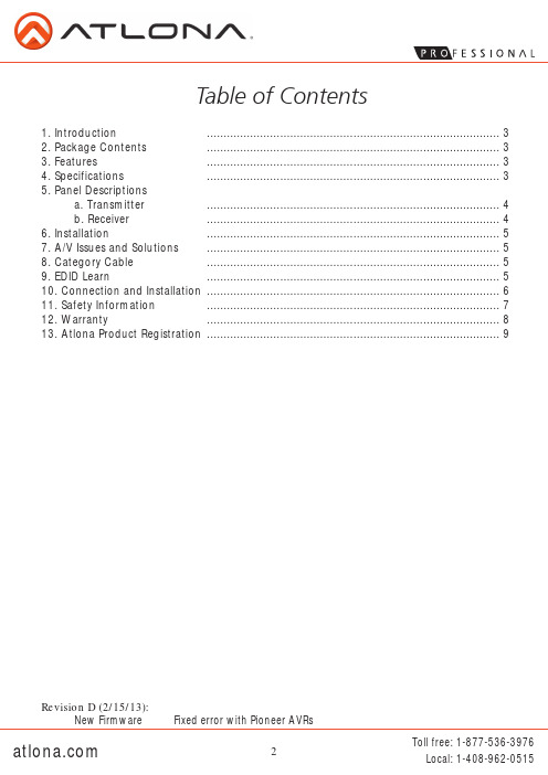
Table of Contents
1. Introduction ........................................................................................ 3 2. Package Contents ........................................................................................ 3 3. Features ........................................................................................ 3 4. Specifications ........................................................................................ 3 5. Panel Descriptions
3G150M 用户手册 v1.01
版权声明目录第1章产品简介 (1)1.1产品简介 (1)1.2产品规格 (2)1.3包装清单 (3)1.4面板指示灯及接口说明 (4)第2章产品硬件安装 (6)2.1硬件安装 (6)2.2网络连接拓扑 (7)第3章如何登录到设备 (11)3.1使用有线网卡连接 (11)3.2使用无线网卡连接 (15)3.3登陆WEB设置界面 (16)第4章工作模式设置向导 (17)4.13G路由器模式设置向导 (17)4.2无线接入点模式设置向导 (22)4.3无线信号放大模式设置向导 (22)4.4无线路由器模式设置向导 (24)第5章高级设置 (27)5.1LAN设置 (27)5.2W AN口设置 (29)5.3MAC地址克隆 (33)5.4域名服务器 (34)第6章无线设置 (35)6.1无线基本设置 (35)6.2无线安全设置 (38)6.3高级设置 (41)6.4WPS设置 (43)6.5无线访问控制 (45)6.6连接状态 (45)第7章DHCP服务器 (46)7.1DHCP服务设置 (46)7.2DHCP列表与绑定 (47)第8章虚拟服务器 (48)8.1端口段映射 (48)8.2DMZ主机 (50)8.3UPNP设置 (51)第9章带宽控制 (51)第10章3G流量统计 (53)10.13G流量统计 (53)10.2上网时间统计 (54)第11章安全设置 (55)11.1客户端过滤 (55)11.2URL过滤 (56)11.3MAC地址过滤 (58)11.4防网络攻击 (59)11.5远程WEB管理 (60)11.6W AN口PING (61)第12章路由设置 (62)第13章系统工具 (63)13.1时间设置 (63)13.2动态DNS (64)13.3备份/恢复设置 (65)13.4恢复出厂设置 (67)13.5软件升级 (68)13.6重启设备 (68)13.7修改登录密码 (69)13.8系统日志 (70)13.9退出登录 (70)附录一设置电脑自动获取IP地址 (71)附录二设备加密后如何设置网卡 (74)附录三名词解释 (76)附录四常见问题解答 (77)附录五3G上网卡兼容清单V 0.5 (81)联系方式 (83)第1章产品简介1.1产品简介感谢您购买3G150M便携式3G路由器/无线接入点/无线路由器(以下简称设备)。
MT-1508 Pocket Auto Range Multimeter用户手册说明书
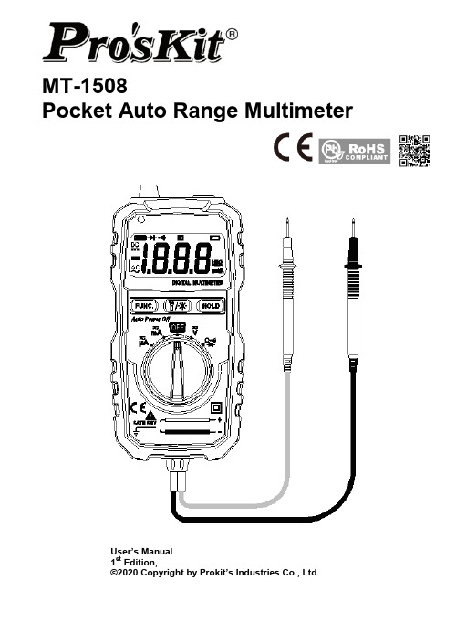
MT-1508Pocket Auto Range MultimeterUser’s Manual1st Edition,©2020 Copyright by Prokit’s Industries Co., Ltd.THE STATEMENTIn accordance with the international copyright law, without permission and written consent, please do not copy the contents of this manual in any form (including storage and retrieval or translation into languages of other countries or regions). The manual is subject to change in future edition without prior notice.Caution“Caution” mark refers to the condition and operation which may cause damage to the instrument or equipment.It requires that you must be careful during the execution of the operation. If you incorrectly perform the operation or do not follow the procedure, it may damage the instrument or equipment. In the circumstances that such conditions are not met or not fully understood, please do not continue to perform any operation indicated by the caution mark.Warning“Warning” mark indicates the condition and operation which may cause danger to u sers.It requires that you must pay attention during the execution of this operation. If incorrectly perform the operation or do not follow the procedure, it may result in personal injury or casualties. In the circumstances that such conditions are not met or not fully understood, please do not continue to perform any operation indicated by the warning mark.Before using the instrument, please read this manual carefully and pay attention to the relevant safety warning information.OVERVIEWThe instrument is a portable digital multimeter. It features stable performance, high accuracy, low power consumption and novel structure, more safe and reliable. I t’s an ideal measuring instrument for users.The instrument can measure DC voltage, AC voltage, DC current, AC current, resistance, diode and connectivity, and non-contact voltage detection function.This manual includes the relevant safety information, warning notices and so on, please read the related contents carefully before using the instrument, and strictly follow all warnings and precautions.SAFETY INSTRUCTIONSThe instrument is designed and manufactured strictly in accordance with the safety standard IEC61010 and in conformity with double insulation, over-voltage standard 600V CAT III and pollution level 2 safety standards.Please follow the manual to use the instrument, otherwise the protection function provided by the instrument may be reduced or invalid.SAFETY OPERATIONWarningIn order to avoid possible electric shock or personal injury, please abide by the following specification:●Before using the instrument, please read the “Safety Instructions” in advance. Use theinstrument in strict accordance with the provisions”, otherwise the protection ability provided by the instrument may be reduced or invalid.●Check the external shell first before using the instrument. Check whether there are anycracks or defects on the plastic parts. Please carefully check the insulator near the input terminal.●If the instrument is not working properly or is damaged, please do not use.●Do not touch the electrified body with more than 30V true effective value AC, 42V AC peak or60V DC.●The instrument shall be used according to the specified measurement category, voltage orcurrent rating.●When it shows low battery indication, please replace the battery in time to avoid anymeasurement error.●Please comply with local and national safety code. Wear personal protection equipment(such as approved rubber gloves, masks and flame retardant clothes, etc.) to prevent being damaged by electric shock and electric arc due to exposed hazardous live conductor.●The voltage applied between input terminals or between each terminal and earth point cannotexceed the specified ratings of the instrument.●Measure a known voltage to determine whether the instrument works properly.●When measuring, correct input terminal, function shift and range shift must be used.●Do not use the instrument around explosive gas, steam or in wet environment.●Do not use damaged probe. Check whether the insulation layer of the probe is damaged,whether there’s any exposed metal or sign of wear. Check the continuity of the probe.●When measuring, please connect the zero line or the ground line first, then connect the livewire; but when disconnecting, please cut off the live wire first, then disconnect the zero line and ground line.●When measuring, please keep your fingers behind the finger protector of the probe.●Before opening the back cover of the instrument, please disconnect the probe from themeasured object.●Do not use the instrument in the environment of exceeding the measurement category (CAT)rating of a single element with the lowest rating among the instrument, probe or accessories.CAT II⏹ INTRODUCTION 1. Flashlight2. Non-contact voltage detecting probe3. Non-contact voltage indicator4. Displaypress and hold it for 2 seconds, the backlight will be turn off. The auto power off function will automatically turn off after approx. 15 seconds of no operation.: Data hold button 7. Red probe of test lead 8. Black probe of test lead General Specifications●Environment condition of use:IEC/EN 61010-1 600V CAT III, pollution level 2 Altitude < 2000 mWorking environment temperature and humidity: 0~40(do not consider when it’s <80% RH, <10)Storage environment temperature and humidity: -10~60(<70% RH, remove the battery) ●Temperature coefficient: 0.1⨯ accuracy /●Maximum voltage allowed between the measuring terminal and the ground: 600V DC or AC RMS●Fuse protection: fuse FF250mA/600V ●Sampling rate: about 3 times/second. ●Display: 3 1/2 bit LCD●Over range indication: LCD display will show “OL”.●e displayed on the LCD display. ●-” ●Power requirement: 2x1.5V AAA batteries ●Dimension: 125*60*26mm Accuracy SpecificationsThe accuracy applies up to one year after the calibration.●Reference condition: environment temperature 18℃ to 28℃, relative humidity is no more than 80%.Frequency range: 40Hz~400Hz;Input protection: Maximum 250V DC or AC RMS.METHOD OF MEASUREMENTAC and DC Voltage Measurement1. Scroll the rotary switch to , press “FUNC.” button, select DC voltage or AC voltagemeasurement.2. Connect the probe in parallel to the circuit or power supply to be measured.3. Read the measuring value from the display. When measuring DC voltage, the display alsoshows the voltage polarity of the red probe test point.Warning●Do not input voltage higher than 600V, it’s possible to display higher voltage, but there maybe risk of damaging the instrument.●When measuring high voltage, be careful to avoid electric shock.●After completing all the measuring operation, make sure to disconnect the probe from themeasured circuit.1. Turn the rotary , press “FUNC.” button, select DC cur rent or AC currentmeasurement.2. Shut off the power supply of the circuit under test. Discharge all the high voltage capacitorson the circuit under test.3. Disconnect the circuit to be measured. Connect the instrument to the circuit to be measuredin series.4. Connect to the power of the circuit, and then read the measuring result from the display. If itdisplays “OL”, it means the input exceeds the measur ing range of the instrument. When measuring the DC and AC, it will show the voltage polarity of red probe test point on the display as well.5. Shut off the power of the circuit under test. Remove the probe of the instrument and restorethe circuit.Warning●To prevent possible electric shock, fire or personal injury, when measuring the current, pleasedisconnect the power of the circuit under test in advance, and fully discharge all the high voltage capacitors, then connect the instrument to the circuit in series.●Do not input above 200mA maximum measurement current value of the instrument,otherwise it may burn the fuse in the instrument.●After completed all the measuring operation, please disconnect the probe from the circuitunder test.1. Turn the rotary switch to ,(if not resistance measurement function, please press2. Connect the probe to the circuit under test in parallel to measure the resistance.3. Read the measuring results from the display.Warning●To prevent possible electric shock, fire or personal injury, before measuring the resistance,please disconnect the power supply of the circuit under test in advance, and fully discharge all the high voltage capacitors.●After completed all the measurement operation, make sure to disconnect the probe from thecircuit under test.Diode Test1. Turn the rotary switch tocathode of the diode to be measured, the reads on the display is the approximate value of diode forward voltage drop. If connected backwards, it will display “OL”.Warning●To prevent possible electric shock, fire or personal injury, before measuring the diode orconnectivity, please disconnect the power supply of the circuit to be measured in advance, and fully discharge all the high voltage capacitors.●If the measured diode is open circuit or in reverse polarity, the instrument will display “OL”. ●After completing all the measurement operations, make sure to disconnect the probe from thecircuit under test.Connectivity Test1. Turnmeasured circuit is less than 50Ω, the buzzer will sound.Warning●To prevent possible electric shock, fire or personal injury, before measuring the diode orconnectivity, please disconnect the power supply of the circuit to be measured in advance, and fully discharge all the high voltage capacitors.●After completing all the measurement operations, make sure to disconnect the probe from thecircuit under test.Non-contact Voltage Detection1. Turn the rotary switch of the instrument to any position except OFF.2. Put the non-contact voltage detecting probe of the instrument close to the live wire of the ACvoltage (less than 5mm).3. The indicator of the non-contact voltage will light up, it shows that there’s AC voltage on thelive wire.INSTRUMENT MAINTENANCEThis section provides the basic maintenance information, including description of replacing fuse and batteries.WarningDo not try to repair the instrument unless you are experienced repair person and have associated calibration, performance test and maintenance information.To prevent possible electric shock, fire or personal injury:●When the cabinet is opened, do not use the instrument to do any measurement.●Remove the input signal before cleaning the instrument.●Specified replacement parts shall be used. Please ask the qualified technicians to repair theinstrument.General MaintenanceUse a damp cloth and a small amount of detergent to clean the housing of the instrument. Please do not use abrasive or chemical solvents.Replace Fuse and BatteryWarning●electric shock or personal injury caused by error reading, when it displays” on the screen, the batteries should be replaced.●period, please remove the batteries to avoid any damage caused by battery leakage.●Use the fuse with specified amperage, fuse ratings, voltage ring and fuse speed.●To avoid electric shock or personal injury, before opening the back cover to replace batteries,the instrument should be shut down and checked to ensure that the probe has already been disconnected from the measuring circuit.Please follow the steps as below to replace the battery:1. Power off the instrument.2. Disconnect the probe from the circuit under test.3. Unscrew and open the cover of battery compartment on the back of this instrument.4. Remove the exhausted batteries, replace with new batteries.5. Close and screw the cover.Please follow the steps as below to replace the fuse:1. Turn off the power of the instrument.2. Disconnect the probe from the circuit under test.3. Unscrew and open the cover on the back of this instrument.4. Remove the damaged fuse, replace with new fuse.5. Close and screw the cover.MT-1508 袖珍型電表使用說明書聲明根據國際版權法,未經允許和書面同意,不得以任何形式(包括存儲和檢索或翻譯為其他國家或地區語言)複製本說明書的任何內容。
Cognex MX-1502 快速参考指南说明书
MX-1502Quick Reference Guide2020June05Revision:1.0.0.10PrecautionsTo reduce the risk of injury or equipment damage,observe the following precautions when you install the Cognex product:l Route cables and wires away from high-current wiring or high-voltage power sources to reduce the risk of damage or malfunction from thefollowing causes:over-voltage,line noise,electrostatic discharge(ESD),power surges,or other irregularities in the power supply.l Changes or modifications not expressly approved by the party responsible for regulatory compliance could void the user’s authority to operate theequipment.l Ensure that the cable bend radius begins at least six inches from the connector.Cable shielding can be degraded or cables can be damaged orwear out faster if a service loop or bend radius is tighter than10X the cablediameter.l This device should be used in accordance with the instructions in this manual.l All specifications are for reference purposes only and can change without notice.LayoutStandard front coverIndicator LEDsSide trigger buttonsPower buttonTouch screenHome buttonSpeaker ventsRecessed area for mobile cameraSlider to lock battery coverBattery coverLanyard hookEnd cap of pistol grip*Trigger button on the pistol grip* *Pistol grip is optional1Using or storing the device outside of the recommended temperature ranges may damage or reduce the lifespan of the battery.Leaving the MX Series Mobile Terminal with a mobile device in direct sunlight for an extended amount of time can raise the temperature above the recommended limit.MX-1502standard front cover model:MX-1502-LR Readers with6.2mm Lens1.Place the rubber insert on the base unit.2.Plug the USB cable into the base unit.3.Put the mobile device on the rubberinsert and connect it to the base unit withthe USB cable.4.Attach the top cover.5.Tighten the screws to fix the top cover.6.Open the back cover to take out thereader battery.7.Plug the pistol grip cable into the gripconnector.8.Insert the reader battery.9.Assemble the reader with the pistol gripand tighten the screws.Installation procedures and specifications are presented in detail in the MX-1502 Reference Manual,which is installed with the DataMan Setup Tool.From the Windows Start menu,select the following to access the manual:All Programs> Cognex>DataMan Software v6.1.0>Documentation.:All cable connectors are keyed to fit the connectors on the reader.not force the connections or damage may occur.Install Software and Documentation and Connect the ReaderTo configure an MX-1502reader,the DataMan Setup Tool software must be installed on a networked PC.The DataMan Setup Tool is available from the DataMan support site:/support/dataman.1.After installing the software,connect the MX-1502to your PC.unch the DataMan Setup Tool and click Refresh.3.Select your MX-1502reader from the list and click Connect.Imager SpecificationsLED WavelengthsThe MX-1502has Regulatory Model R00045(inductive)and Regulatory ModelR00079(non-inductive),and meets or exceeds the requirements of all applicable standards organizations for safe operation.However,as with any electrical equipment,the best way to ensure safe operation is to operate them according to the agency guidelines that follow.Please read these guidelines carefully before using your device.The following specifications apply to the MX-1502readers:CanadianKoreaJapanese StatementFor European Union UsersCognex complies with Directive2012/19/EU OF THE EUROPEAN PARLIAMENT AND OF THE COUNCIL of4July2012on waste electrical and electronic equipment (WEEE).This product has required the extraction and use of natural resources for its production.It may contain hazardous substances that could impact health and the environment,if not properly disposed.diminish the pressure on the natural resources,we encourage you to use the appropriate take-back systems for product disposal.Those systems will reuse or recycle most of the materials of the product you are disposing in a sound way.The crossed out wheeled bin symbol informs you that the product should not be disposed of along with municipal waste and invites you to use the appropriate separate take-back systems for product disposal.If you need more information on the collection,reuse,and recycling systems,please contact your local or regional waste administration.You may also contact your supplier for more information on the environmental performance of this product.Compliance Statements:Wireless Charging StationThe Wireless Charging Station has Regulatory Model1ABA(inductive)and Regulatory Model R00080(non-inductive),and meets or exceeds the requirements of all applicable standards organizations for safe operation.However,as with any electrical equipment,the best way to ensure safe operation is to operate them according to the agency guidelines that follow.Please read these guidelines carefully before using your device.Laser safety statement:Illumination and Lens assembly:This device has been tested inwith IEC60825-13rd ed.,2014.,and has been certified to be the limits of a Class2Laser device.Cognex complies with Directive2012/19/EU OF THE EUROPEAN PARLIAMENT AND OF THE COUNCIL of4July2012on waste electrical and electronic equipment (WEEE).This product has required the extraction and use of natural resources for its production.It may contain hazardous substances that could impact health and the environment,if not properly disposed.In order to avoid the dissemination of those substances in our environment and to diminish the pressure on the natural resources,we encourage you to use the appropriate take-back systems for product disposal.Those systems will reuse or recycle most of the materials of the product you are disposing in a sound way.The crossed out wheeled bin symbol informs you that the product should not be disposed of along with municipal waste and invites you to use the appropriate separate take-back systems for product disposal.If you need more information on the collection,reuse,and recycling systems,please contact your local or regional waste administration.You may also contact your supplier for more information on the environmental performance of this product.CanadianKorean Statement Japanese StatementCompliance)根据中国大陆《电子信息产品污染控制管理办法》( 也称为中国大陆RoHS),以下部份列出了本产品中可能包含的有毒有害物质或元素的名称和含量。
A1508系列温控表
A1508系列温控表A1508系列温控表使用操作说明书特点:⊙热电偶/热电阻/模拟信号通用,软件选择输入 ⊙具有显示、报警、调节功能 ⊙采用先进双自由度PID 算法⊙具备不同系统(快速升降温和慢速加热系统)的自整定功能⊙多种控制输出选择,模块化设计 ⊙抗干扰能力强⊙开关电源100-240V AC⊙适用于系统温度控制场合为了您的安全,在使用前请仔细阅读以下内容!※请遵守下面的要点警告如果不按照说明操作会发生意外。
注意 如果不按照说明操作会导致产品毁坏。
1. 在以下情况下使用这个设备,如(核能控制、医疗设备、汽车、火车、飞机、航空、娱乐或安全装置等),需要安装安全保护装置,或联系我们索取这方面的资料,否则会引起严重的损失,火灾或人身伤害。
2. 必须要安装面板,否则可能会发生触电。
3. 在供电状态中不要接触接线端子,否则可能会发生触电。
4. 不要随意拆卸和改动这个产品,如确实需要请联系我们,否则会引起触电和火灾。
5.请在连接电源线或信号输入时检查端子号,否则会引起火灾。
1.这个装置不能使用在户外。
否则会缩短此产品的使用寿命或发生触电事故。
2.当电源输入端或信号输入端接线时,NO.20AMG(0.50m ㎡)螺丝拧到端子上的力矩为0.74·m-0.9n ·m 否则可能会发生损坏或连接端子起火。
3.请遵守额定的规格。
否则会缩短这个产品的寿命后发生火灾。
4.清洁这个产品时,不要使用水或油性清洁剂。
否则会发生触电或火灾,也将损坏本产品。
5.在易燃易爆,潮湿,太阳光直射,热辐射,振动等场所应避免使用这个单元。
否则可能会引起爆炸。
6.在这个单元中不能有流尘或沉淀物。
否则可能会引起火灾或机械故障。
7.不要用汽油,化学溶剂清洁仪表外壳。
使用这些溶剂会损害仪表外壳。
请用柔软的湿布(水或酒精)清洁塑料外壳。
一、仪表型号二、型号说明三、主要技术参数1、整机参数2、输入(4-20MA. 1-5V输入可订做)3、输出四、面板名称五、面板按键操作1、SET键:在正常显示状态下,点动SET键可进入SV设置菜单,长按SET键可以进入设置菜单。
- 1、下载文档前请自行甄别文档内容的完整性,平台不提供额外的编辑、内容补充、找答案等附加服务。
- 2、"仅部分预览"的文档,不可在线预览部分如存在完整性等问题,可反馈申请退款(可完整预览的文档不适用该条件!)。
- 3、如文档侵犯您的权益,请联系客服反馈,我们会尽快为您处理(人工客服工作时间:9:00-18:30)。
C1 L2 R4
R3
C7
C8=0.1uF R5=2.2K
C9 470P
R7 2.2M
C11=0.1uF
图 1 MX1508RX2 典型应用线路图 MX1508RX2 的应用线路图如图 1 所示,其中 LEFT 和 RIGHT 用于驱动转向轮,BACKWARD 和 FORWARD 用 于驱动后轮马达。 特别注意事项: 图 1 中的功率电源 VMx(x=1,2)对地去耦电容(C13)容值应根据具体的应用调整,VMx(x=1,2)电压越高,输 出峰值电流越大,C13 取值越大,但是电容 C13 的取值至少需要 0.1uF。在高压、大电流的应用条件下建议 电容 C13 取值 100uF。 图 1 中左转/右转马达和前进/后退马达之间都需要添加一个 104 电容。 PCB 设计时,必须确保电路板的高频部分尤其是天线部分远离电机,否则电路易受到电机噪声的影响, 造成误码。此外,电机两端必须跨接 104 电容,否则电路极易受到电机噪声干扰,出现接收距离下降、误 码等现象。
34(W1)
前进和向右
后退
40(W1)
后退
后退和向右
46(W1)
后退和向右
后退和向左
52(W1)
后退和向左
向左
58(W1)
向左
向右
64(W1)
向右
3
MX1508RX2
绝对最大额定值(TA=25℃)
参数
符号
值
单位
最大功率电源电压 最大外加输出端电压
VM(MAX)
8
V
VOUT(MAX)
VM
最大峰值输出电流 1 通道 2 通道
(2)、不同环境温度下的最大功耗计算公式为: PD=(150℃-TA)/θJA TA 表示电路工作的环境温度,θJA 为封装的热阻。150℃表示电路的最高工作结温。
(3)、电路功耗的计算方法: P =I2xR
其中 P 为电路功耗,I 为持续输出电流,R 为电路的导通内阻。电路功耗 P 必须小于最大功耗 PD
五功能马达驱动电路
MX1508RX2
五功能马达驱动电路 MX1508RX2
概述
MX1508RX2 是为遥控汽车等玩具设计的专用单芯片解决方案,该芯片将传统方案的 RX2 接收解码芯片 以及马达驱动芯片整合为单一芯片。芯片内部集成两路 H 桥驱动电路,可同时驱动转向电机以及前进后退 电机。
单通道工作时,左转/右转通道用于驱动转向电机,最大持续输出电流达到 1.2A,最大峰值输出电流达 到 1.5A。前进/后退通道用于驱动前进后退电机,最大持续输出电流达到 1.4A,最大峰值输出电流达到 2A; 双通道同时工作时,左转/右转通道持续输出 0.8A 的情况下,前进/后退通道能持续输出 1.2A。
LDO 参数测试
负载=240Ω VM=6.5V TA=25℃
2.593
LDO 输出电压
负载=2KΩ VM=6.5V TA=25℃ VVDD VM=3V TA=25℃ 空载
2.594 V
2.584
VM=6.5V TA=25℃ 空载
2.595
解码频率
内置振荡频率
FOSC
128
kHz
允许发射频率的偏差
77
功能框图
13 VDD
LDO
带隙基准电路
振荡器
时序控制
2 SI 放大器
解码电路
逻 辑 电 路
14 VI1
15 VO1
过热保护电路
16 VI2 1 VO2
AGND 4
PGND VM1
12
栅
驱
动
FORWARD 11
电
路
PGND
VM1
栅
驱
动
BACKWARD 10
电
路
PGND 9
TURBO 3
VM2 5
栅
驱
动
465
uA
1 通道导通内阻 2 通道导通内阻
IO=±100mA VM1=6.5V TA=25℃ RON1 IO=±1000mA VM1=6.5V TA=25℃
IO=±100mA VM2=6.5V TA=25℃ RON2 IO=±1000mA VM16 0.470
反转模式的定义为:按键后退或者左转时,此时马达驱动端 BACKWARD 或 LEFT 输出高电平,马达驱动 端 FORWARD 或 RIGHT 输出低电平时,马达驱动电流从 BACKWARD 或 LEFT 流入马达,从 FORWARD 或 RIGHT 流到地端,此时马达的转动定义为反转模式。
VM
VM
3、驱动电路最大持续功耗 该系列马达驱动电路内部均设计有过热保护电路,因此当驱动电路消耗的功耗过大时,电路将进入热关
断模式,热关断状态下马达将无法正常工作。驱动电路最大持续功耗的计算公式为:
PD=(150℃-TA)/θJA 其中 150℃为热关断电路预设温度点,TA 为电路工作的环境温度(℃),θJA 为电路的结到环境的热阻(单 位℃/W)。注意:驱动电路的最大持续功耗与环境温度、封装形式以及散热设计等因素有关,与电路导通内 阻并无直接关系。
6
MX1508RX2
应用说明
1、基本工作模式 a)待机模式
在不按键的情况下,电路处于待机模式。包括驱动功率管在内的所有内部电路都处于关断状态。电路消 耗极低的电流。此时马达输出端 FORWARD、BACKWARD、RIGHT 和 LEFT 都为高阻状态。 b)正转模式
正转模式的定义为:按键前进或者右转时,此时马达驱动端 FORWARD 或 RIGHT 输出高电平,马达驱动 端 BACKWARD 或 LEFT 输出低电平时,马达驱动电流从 FORWARD 或 RIGHT 流入马达,从 BACKWARD 或 LEFT 流到地端,此时马达的转动定义为正转模式。 c)反转模式
4、驱动电路功耗 马达驱动电路内部功率 MOSFET 的导通内阻是影响驱动电路功耗的主要因素。驱动电路功耗的计算公式
为:PD=IL2 xRON 其中 IL 表示马达驱动电路的输出电流,RON 表示功率 MOSFET 的导通内阻。 注意:功率 MOSFET 的导通内阻随着温度的升高而升高,在计算电路的最大持续输出电流以及功耗时必
引脚定义
引脚编号
1 2 3 4 5 6 7 8 9 10 11 12 13 14 15 16
引脚名称
VO2 SI
TURBO AGND VM2 RIGHT LEFT PGND PGND BACKWARD FORWARD VM1 VDD
VI1 VO1 VI2
输入/输出 O I O O O O O O I O I
VM
OFF
OFF ON
OFF OFF
ON
M
M
M
OFF
OFF OFF
ON
ON
OFF
a)待机模式
b)正转模式
c)反转模式
2、过热保护电路 当驱动电路结温超过预设温度时,TSD 电路开始工作,此时控制电路强制关断所有输出功率管,驱动电
路输出进入高阻状态。TSD 电路中设计了热迟滞,只有当电路的结温下降到预设温度时,电路返回正常工作 状态。
推荐工作条件(TA=25℃)
参数
符号
最小值
典型值(VM=6.5V)
最大值 单位
功率电源电压
VM
2
--
8
V
TA=25℃
1 通道
IOUT1
1.4
独立工作持续输出电流
2 通道
IOUT2
TA=25℃
1 通道
IOUT1
1.2 A
1.2
同时工作持续输出电流
2 通道
IOUT2
0.8
注: (1)、VM 代表 VM1 和 VM2,1 通道代表 FORWARD 和 BACKWARD 通道,2 通道代表 FIGHT 和 LEFT 通
引脚功能描述
用于信号放大的反相器 2 输出端 编码信号输入端
加速功能输出端
控制部分电源地
左转右转马达 2 的输入电源 马达 2 右转输出端 马达 2 左转输出端 功率地
功率地
马达 1 后退输出端 马达 1 前进输出端 前进后退马达 1 的输入电源 LDO 输出端 用于信号放大的反相器 1 输入端 用于信号放大的反相器 1 输出端 用于信号放大的反相器 2 输入端
1
R8=2.2K
2
2300
3
4
VO2 SI TURBO AGND
5 VM2
6 RIGHT
7 LEFT
8 PGND
VI2 16 VO1 15 VI1 14 VDD 13 VM1 12 FORWARD 11 BACKWARD 10 PGND 9
C13=0.1uF-100uF
前进/后退马达
M
MX1508RX2
IOUT(PEAK)
2 1.5
A
最大功耗 结到环境热阻 工作温度范围 结温 储存温度
PD
1.1
W
θJAD
80
℃/W
Topr
-20~+85
℃
TJ
150
℃
Tstg
-55~+150
℃
焊接温度
TLED
260℃,10 秒
注:(1)、VM 代表 VM1 和 VM2,1 通道代表 FORWARD 和 BACKWARD 通道,2 通道代表 FIGHT 和 LEFT 通道。
179 kHz
注:(1)、VM 代表 VM1 和 VM2,1 通道代表 FORWARD 和 BACKWARD 通道,2 通道代表 FIGHT 和 LEFT 通道。
5
典型应用线路图
C2
L1
C6
R2
Q1 C2712 R1