中达优控触摸屏-OP320-430参数
中达优控PLC触摸屏一体机说明书及详细参数
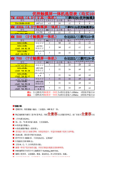
TM
430B(4.3寸文本一体机)
型号
开孔尺寸 文本尺寸 总点数
三输菱入FX2继N电+出器优输控晶触体出摸管输屏MD430
TM-20MR-430-B
163*112
4.3
20
12
8
0
MM
430A(4.3寸触摸屏一体机)
MM型-2号0MR-
开孔尺寸 HMI尺寸 总点数
0
0
无 三菱FX1S 398元/台
FX1S+优控触摸屏S500A
温度
AD
0
0
2 路 10K NTC
(-50℃至+150
2
℃)
2 路 K 型热电 偶
2
DA
485通信 PLC软件 价格
0
1路 台达ES2 450元/台
2
无
台达ES2 468元/台
2
无 三菱FX1S 498元/台
FX1N+优控触摸屏S700A
24 24 24
16 16 16
ቤተ መጻሕፍቲ ባይዱ
12 12 12
MM-40MR12MT_700_FX_C
204*150*5 0.9
7
52
24
16
12
注1:台达ES系列触摸屏一体机为4路高速输入100khz 4路脉冲输出100khz 继电器输出最大负载 注2:三菱FX系列触摸屏一体机为2路高速输入100khz 2路脉冲输出100khz 继电器输出最大负载
温度
AD
DA
485通信 PLC软件
0
0
2 路 10K NTC
(-50℃至+150
星光莱特 LT-320触摸式控制屏操作说明说明书

本文档只针对北京星光莱特电子有限公司生产的LT-320新型触摸式控制屏做操作说明,部分相关设置使用附带的LC灯光控制软件。
LC详细操作请参软件相关使用说明。
LT-320触摸式控制屏使用说明北京星光莱特电子有限公司BEIJING STARLIGHT ELECTRONICS CO.,LTD北京市大兴区西红门镇星光巷7号100076新的LT-320触摸式控制屏基于LC软件编程,通过PC软件实现电脑对终端设备和触摸屏的设置。
对终端设备的设置包括:地址设置,区域设置,亮度设置,场景保存和场景检查。
对触摸屏的设置包括:按键设置,定时设置,天文时间。
使用LC控制软件将更加快捷方便的赋予触摸屏更加强大的功能。
一.接线示意图:(接线之前,先给USB-RS-485安装驱动程序,见光盘)接通电源,进入初始画面如下:二.点击屏幕左下角的“LIGHTSPACE”,进入输入密码画面,输入正确密码(默认为1665)后,按“确定”后,进入“主菜单”画面。
1.联机设置点击“联机设置”菜单,液晶屏显示如下界面,只有在此界面下方可使用LC软件对触摸屏进行有效编程。
点击“返回”回到上级菜单。
2.设置语言点击“设置语言”菜单,触摸屏提供中英文两种语言选择,点击选中任一种语言,该语种背景反白,则设置成功。
点击“返回”键回到上级菜单。
3.初始化设置点击“初始化设置”菜单,触摸屏界面如下,初始化设置将使触摸屏当前的一切设置丢失,返回到出厂状态,请慎重操作。
点击“返回”键回到上级菜单。
4.更新时间点击“更新时间”菜单,触摸上下箭头更改年,月,日,星期及时间值,按“确定”键确认更改。
点击“返回”键回到上级菜单。
5.修改密码点击“修改密码”菜单,进入修改密码菜单,按照提示设定四位新密码,设置好后点击“确定”键。
放弃修改请点击“取消”。
点击“返回”键回到上级菜单。
6.液晶亮度点击“液晶亮度”菜单,进入液晶亮度设置菜单,点击上下箭头改变亮度。
点击“返回”键回到上级菜单。
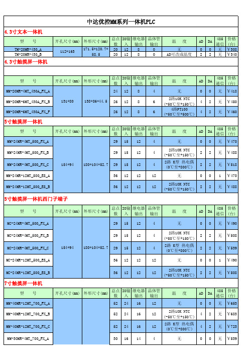
中达优控MM系列一体机PLC
0
0
422/ 485
¥620
C-60MT-001
175*90*75 60 36 24
4
4
0
0
422/ 485
¥620
优控单板PLC系列
型号
开孔尺寸(mm)
外形尺寸(mm)
总点 IO输 继电器 数 入 输出
晶体管 输出
温度
AD
DA
485 通信
价格 (台)
YK-20MR-C YK-30MR-C
145*76 172.4*90.5
24 12 8 36 16 14
4
2路10K NTC (-50℃至+150℃)
2
2 232 ¥160
6
4路10K NTC (-50℃至+150℃)
4
2 232 ¥220
优控放大板系列
型号
开孔尺寸(mm)
外形尺寸(mm)
总点 IO输 继电器 数 入 输出
晶体管 输出
配继电器
价格 (台)
K4EYR-G
4
MM-40MR-12MT_700_ES_B
52 24 16
12
2路10K NTC (-50℃至+150℃)
4
2
无 ¥653
MM-40MR-12MT_700_ES_C
52 24 16
12
2路 K型 热电偶 (0℃至+800℃)
4
2
无 ¥683
MM-40MR-12MT_700_ES_D
52 24 16
12
4.3寸文本一体机
型号 TM-20MR-430_A TM-20MR-430_B
4.3寸触摸屏一体机
中达-室外_源干接_配置
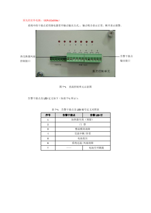
原先的室外电源:(SUP182A386A )系统中的干接点采用继电器常开触点输出方式,,触点吸合表示正常,断开表示报警。
图7-1 直流控制单元示意图告警干接点及LED 定义如下(如表7-1所示):表7-1 告警干接点及LED 编号定义对照表热交换器风扇 控制接口告警干接点 输出接口最近出货的:(WPS-48/150ZCE)系统提供8路输出干接点,每一路提供3个接线端子,从左至右为常闭点,公共点,常开点,客户可根据需要自行选择。
干接点的告警定义如下:以上干接点排列可参考图2-7。
根据客户需求,可在监控单元中自行定义告警内容。
NO COM NC交流异常NO COMNC模块故障NO COM NC门禁告警NO COM NC防雷故障NO COM NC电池低压NOCOM NC电池空开断NOCOM NCNOCOM NC过温/风扇故障预留图2-7 干接点示意表格中第1路“交流异常”干接点与其它7路干接点不同。
当交流正常时,公共点与常开点闭合,与常闭点断开;当交流异常时,公共点与常开点断开,与常闭点闭合。
而其它7路干接点,当无告警时,公共点与常开点断开,与常闭点闭合;当有告警时,公共点与常开点闭合,与常闭点断开。
2012-6-18出货的(CUC-19HA )系统提供4路输出干接点,每一路提供两个接线端子,正常常开,告警常闭。
告警干接点系统描述告警干接点自定义配置:1 按回车键进入系统设置2 输入666666超级密码3 进入告警类型选项4 选择干接点告警设置5 配置干接点接口6 回车保存。
MD204L OP320说明书
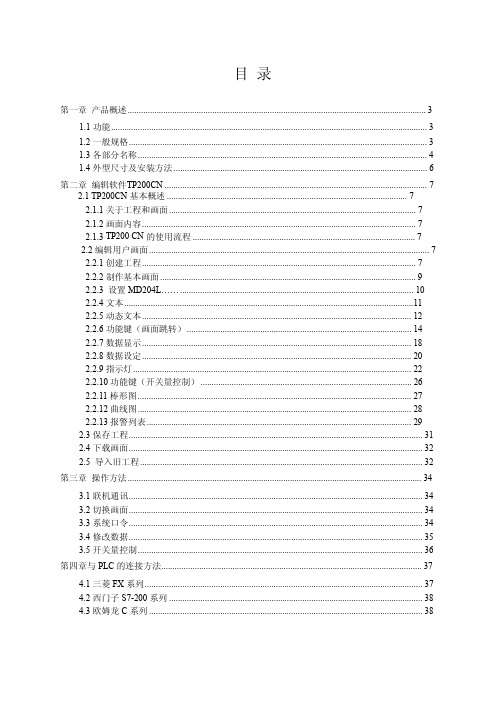
4.1 三菱 FX 系列............................................................................................................................. 37 4.2 西门子 S7-200 系列 .................................................................................................................. 38 4.3 欧姆龙 C 系列 ........................................................................................................................... 38
第三章 操作方法.................................................................................................................................... 34
3.1 联机通讯.................................................................................................................................... 34 3.2 切换画面.................................................................................................................................... 34 3.3 系统口令.................................................................................................................................... 34 3.4 修改数据.................................................................................................................................... 35 3.5 开关量控制................................................................................................................................ 36
MIC3203 MIC3203-1高亮LED驱动控制器评估板说明书

MIC3203/MIC3203-1 Evaluation BoardHigh Brightness LED Driver Controllerwith High-Side Current SenseMicrel Inc. • 2180 Fortune Drive • San Jose, CA 95131 • USA • tel +1 (408) 944-0800 • fax + 1 (408) 474-1000 •General DescriptionThe MIC3203/MIC3203-1 is a hysteretic step-down, constant-current, High-Brightness LED (HB LED) driver. It provides an ideal solution for interior/exterior lighting, architectural and ambient lighting, LED bulbs, and other general illumination applications.This board enables the evaluation of the MIC3203/MIC3203-1 for 1A LED current. The board is optimized for ease of testing, with all the components on a single side. The device operates from a 4.5V to 42V input voltage range, and controls an external power MOSFET to drive high current LEDs. When the input voltage approaches and crosses UVLO threshold, the internal 5V VCC is regulated and the external MOSFET is turned on if EN pin and DIM pin are high. The inductor current builds up linearly. When the CS pin voltage hits the V CS(MAX) with respect to V IN , the external MOSFET is turned off and the Schottky diode takes over and returns the current to V IN . Then the current through inductor and LEDs starts decreasing. When CS pin hits V CS(MIN), the external MOSFET is turned on and the cycle repeats.Since the control scheme does not need loop compensation, it makes for a very simple design and avoids problems of instability.RequirementsThis board needs a single bench power source adjustable over the input voltage of 4.5V < V IN < 42V that can provide at least 1A of current. The loads can either be active (electronic load) or passive (LEDs) with the ability to dissipate the maximum load power while keeping accessible surfaces ideally < 70°C. PrecautionsThere is no reverse input protection on this board. When connecting the input sources, ensure that the correct polarity is observed.Under extreme load conditions input transients can be quite large if long test leads are used. In such cases a 100µF, 63V electrolytic capacitor is needed at the V IN terminals to prevent over voltage damage to the IC.Getting Started1. Connect V IN supply to the input terminals V INand GND . With the output of this supply disabled, set its voltage to the desired input test voltage (4.5V < V IN < 42V). This supply voltage should be monitored at the test boards input terminals to allow voltage drops in the test cables (and ammeter if used) to be accounted for. An ammeter can be added inline with the +V IN input terminal to accurately measure input current.Connect the LEDs to the output terminals between LED+ and LED −. This LED voltage drop depends on manufacturer tolerance and number of LEDs. The LED current can be measured using an ammeter or current probe. A 4.7µF ceramic capacitor helps to reduce the current ripple through the LED. The LED current is set to 1A by current sense resistor R CS i.e., 200m Ω.Selecting the sense resistor refers to the table given in data sheet application sub-section.2. Enable the input supply . By default, thecontroller is enabled when the input voltage approaches UVLO threshold and crosses 5V, the internal 5V VCC is regulated and the external MOSFET is turned on if EN pin and DIM pin are high. To use the EN and DIM functions of the MIC3203/MIC3203-1, a test point is provided for each of them.Ordering InformationPart Number Description MIC3203YM EV Evaluation board with MIC3203YM device MIC3203-1YM EVEvaluation board with MIC3203-1YM deviceOther FeaturesR CS is given byI V +V (x 21=R LED)MIN (CS )MAX (CS CS Error! Bookmark notdefined.EN InputThe EN pin provides a logic level control of the output and the voltage has to be 2.0V or higher to enable the current regulator. The output stage is gated by the DIM pin. When the EN pin is pulled low, the regulator goes to off state and the supply current of the device is reduced to below 1µA. In the off state, the output drive is placed in a "tri-state" condition, where MOSFET is in an “off” or non-conducting state. Do not drive the EN pin above the supply voltage.I LED is LED current required to set.For V CS(MAX) and V CS(MIN) , refers to electrical characteristics table in the data sheet.To calculate the frequency spread across input supply: )V +V (×I Δ×L )V R ×I V (×)V +R ×I +V (=F IN D L LED CS LED IN LED CS LED D SW --CS)MIN (CS )MAX (CS L R V V =I Δ-DIM InputThe DIM pin provides a logic level control for brightness of the LED. A PWM input can be used to control the brightness of LED. DIM high enables the output and its voltage has to be 2.0V or higher. DIM low disables the output, regardless of EN high state.where : V D is Schottky diode forward drop V LED is total LEDs voltage drop V IN is input voltageI LED is average LED currentCurrent Sense InputAccording to the above equation, choose the inductor to make the operating frequency no higher than 1.5MHz. The CS pin provides the high-side current sense to set the LED current with an external sense resistor.Refer to the datasheet “Application Information” for more information on components selection guidelines.A sense resistor R CS is placed between V IN and LED+ terminal.Frequency DitheringThe current flowing through LED is sensed and current feedback is provided to the hysteretic step-down regulator. The MIC3203 is designed to modulate the V CS(MAX) with amplitude ±6mV by a pseudo random generator to generate the ±12% of the switching frequency dithering to spread the frequency spectrum over a wider range and reduce the EMI noise peaksThe MIC3203-1 is non-dithering version of the MIC3203.Evaluation Board Performance* With regards to V INEvaluation Board SchematicNotes:1. If bulk capacitor on input rail is away (4 inches or more) from the MIC3203/MIC3203-1, install the 100µF bulk capacitor near V IN.2. Source impedance should be as low as 10mΩ.Bill of MaterialsItem Part Number Manufacturer DescriptionQty. 12105C475KAZ2AAVX (1) GRM32ER71H475KA88L Murata (2) C1, C2, C5C3225X7S1H475M TDK (3) 4.7µF/50V, Ceramic Capacitor, X7R, Size 1210 308053D105KAT2AAVX (1) 1µF/25V, Ceramic Capacitor, X5R, Size 0805 GRM21BR71E105KA99L Murata (2)1µF/25V, Ceramic Capacitor, X7R, Size 0805 C3C2012X7R1E105KTDK (3) 1µF/25V, Ceramic Capacitor, X7R, Size 0805 1(Open) 08055A271JAT2A AVX (1) 270pF/50V, Ceramic Capacitor NPO, Size 0805 C4(Open) GRM2165C2A271JA01DMurata (2) 270pF/100V, Ceramic Capacitor NPO, Size 08051SK36-TPMCC (4) SK36Fairchild (5) D1SK36-7-F Diode (10)60V, 3A, SMC, Schottky Diode 1 L1 SLF10145T-680M1R2 SUMIDA (6) 68µH, 1.2A, SMT, Power Inductor 1 M1 FDS5672 Fairchild (11) MOSFET, N-CH, 60V, SO-8 1 R1 CSR 1/2 0.2 1% I StackpoleElectronics Inc (7)0.2Ω Resistor, 1/2W, 1%, Size 1206 1 R2, R3CRCW08051003FKEAVishay (8) 100k Ω Resistor, 1%, Size 0805 2 R4 CRCW08050000FKEA Vishay (8) 0 Ω Resistor, 1%, Size 0805 1 R5 (Open) CRCW08052R20FKEA Vishay (8) 2.2 Ω Resistor, 1%, Size 0805 1 R6 CRCW08051002FKEAVishay (8)10k Ω Resistor, 1%, Size 08051MIC3203YMHigh Brightness LED Driver Controller with High-Side Current Sense-Frequency DitheringU1MIC3203-1YMMicrel, Inc.(9)High Brightness LED Driver Controller withHigh-Side Current Sense-Frequency Non-Dithering1Notes: 1. AVX: 2. Murata: 3. TDK: 4. MCC: 5. Fairchild: 6. Sumida Tel: 7. Stackpole Electronics: 8. Vishay: 9. Micrel, Inc.: PCB Layout RecommendationsLayerTopTopAssemblyBottom Layer。
大彩光电 DC32240M035_1110_0X(T N) 医用级 3.5 寸 HMI 触摸屏说明书
广州大彩光电科技有限公司版权所有版本记录销售与服务广州大彩光电科技有限公司电话:************-601传真:************Email:*************(咨询和支持服务)网站:地址:广州黄埔区(科学城)玉树华新园C栋3楼网络零售官方旗舰店:https://目录1. 硬件介绍 (1)1.1产品外观 (1)1.2硬件配置 (1)1.3调试工具 (2)2. 产品规格 (3)3. 产品尺寸 (5)4. 引脚定义 (6)5. 可靠性测试 (7)5.1ESD测试 (7)5.1.1执行标准 (7)5.1.2测试环境 (7)5.1.3测试数据 (8)5.2高低温老化测试 (8)5.2.1测试环境 (8)5.2.2测试数据 (9)5.3群脉冲测试 (9)5.3.1执行标准 (9)5.3.2测试环境 (9)5.3.3测试数据 (9)5.4辐射测试 (10)5.4.1执行标准 (10)5.4.2测试环境 (10)5.4.3测试数据 (10)6. 型号定义 (12)7. RS232与TTL电平转换 (13)8. 协议配置 (14)9. LUA脚本配置 (15)10. 包装与物理尺寸 (16)11. 产品架构 (17)12. 开发软件 (18)12.1什么是虚拟串口屏 (18)12.2Keil与虚拟串口屏绑定调试 (19)13. 开发文档 (20)14. 免责声明 (21)1. 硬件介绍本章节主要介绍产品的一些外观参考图、硬件配置图和调试所需工具。
1.1 产品外观以下为该尺寸不同型号的外观参考图,如图1-1、图1-2所示。
注:未涉及关键结构工艺修改或布局大调整,仅产品工艺或可靠性方面的变更迭代,公司不予对外发起变更,具体以收到的实物为准。
图1-1 3.5寸电阻触摸参考图图1-2 3.5寸无触摸参考图1.2 硬件配置以下为该尺寸产品硬件配置参考图,以电阻屏举例说明,如图1-3所示。
图1-3硬件配置图销售咨询:************-601Email:*************1.3 调试工具以下为该产品调试工具参考图,以电阻屏举例说明,如图1-4所示。
PanelView 5310 终端 用户手册说明书
目录
概述 安装 PanelView 5310 终端
配置终端设置
前言
变更摘要. . . . . . . . . . . . . . . . . . . . . . . . . . . . . . . . . . . . . . . . . . . . . . . . . 7 包装清单. . . . . . . . . . . . . . . . . . . . . . . . . . . . . . . . . . . . . . . . . . . . . . . . . 7 索取开源软件包的对应源代码 . . . . . . . . . . . . . . . . . . . . . . . . . . . . . . 8 产品固件和发行说明 . . . . . . . . . . . . . . . . . . . . . . . . . . . . . . . . . . . . . . 8 其他资源. . . . . . . . . . . . . . . . . . . . . . . . . . . . . . . . . . . . . . . . . . . . . . . . . 9
第1章
关于 PanelView 5310 终端 . . . . . . . . . . . . . . . . . . . . . . . . . . . . . . . . 11 硬件特性. . . . . . . . . . . . . . . . . . . . . . . . . . . . . . . . . . . . . . . . . . . . . . . . 12 操作员控制. . . . . . . . . . . . . . . . . . . . . . . . . . . . . . . . . . . . . . . . . . . . . . 13 触摸手势. . . . . . . . . . . . . . . . . . . . . . . . . . . . . . . . . . . . . . . . . . . . . . . . 13 Studio 5000 环境 . . . . . . . . . . . . . . . . . . . . . . . . . . . . . . . . . . . . . . . . 14 EtherNet/IP 通信 . . . . . . . . . . . . . . . . . . . . . . . . . . . . . . . . . . . . . . . . 15 典型配置. . . . . . . . . . . . . . . . . . . . . . . . . . . . . . . . . . . . . . . . . . . . . . . . 15 产品目录号说明 . . . . . . . . . . . . . . . . . . . . . . . . . . . . . . . . . . . . . . . . . 15 产品选择. . . . . . . . . . . . . . . . . . . . . . . . . . . . . . . . . . . . . . . . . . . . . . . . 16 附件. . . . . . . . . . . . . . . . . . . . . . . . . . . . . . . . . . . . . . . . . . . . . . . . . . . . 16 以太网电缆. . . . . . . . . . . . . . . . . . . . . . . . . . . . . . . . . . . . . . . . . . . . . . 17
十大触控一体机品牌技术参数
目录一、希沃 (1)70寸技术参数 (1)图片示例 (2)二、TCL (3)70寸技术参数 (3)图片示例 (4)65寸技术参数 (5)三、上海广电光显 (6)技术参数 (6)四、长虹 (7)65寸技术参数 (7)五、鸿合科技 (8)70寸技术参数 (8)六、创维光电 (8)70寸技术参数 (9)图片示例 (10)84寸技术参数 (11)65寸技术参数 (12)七、上海仙视 (12)70寸技术参数 (12)图片示例 (14)84寸技术参数 (15)八、夏普 (16)70寸技术参数 (16)80寸技术参数 (17)图片示例 (19)九、创显光电 (19)70寸技术参数 (20)84寸技术参数 (21)图片示例 (22)十、深圳中银科技 (23)70寸技术参数 (23)一、希沃70寸技术参数图片示例70寸图片165寸图片2二、TCL70寸技术参数图片示例70寸图片365寸图片465寸技术参数三、上海广电光显技术参数四、长虹65寸技术参数五、鸿合科技70寸技术参数产品规格:70英寸型号:HD-I7002E背光类型:LED显示比例:16:9可视角度:178°物理解析度:1920*1080Pixel图像制式/声音制式:PAL/DK,I3D功能:——工作电压:AC 90-265V,50/60Hz触摸表面材质:钢化玻璃感应方式:红外感应触摸技术特性:HID免驱触摸点数:多点触控,多点书写书写方式:手指或书写笔触摸分辨率:32767*32767通讯接口: USB存储温度/湿度:-20℃~60℃,10%~90% 工作温度/湿度:5℃~50℃,10%~90% 安装方式:壁挂或移动整机尺寸:1648.9*975.6*112.9mm重量:70KG六、创维光电70寸技术参数图片示例70寸图片565寸图片6七、上海仙视70寸技术参数图片示例八、夏普 70寸技术参数 电力消耗(W ) 230W 待机消耗功率(W ) 0.50电源要求 交流110-240V ,50Hz 屏幕显示语言 英文/中文(简体)/俄语 扬声器 (150mm×34mm )×2音频输出功率 10W×2(AV 输入,负载4欧姆,失真度为10%时) 电视调谐系统 自动预设99个频道视频彩色制式 PAL/SEAM/NTSC3.58/PAL60图像清晰度* RD 模拟信号:水平>=350,垂直>=400以上 SDTV :水平>=450,垂直>=450以上 背光源 LED 重量kg 57.5KG 外型尺寸(cm )宽×深×高 1.625 ×106 ×993mm液晶显示屏 X-GEN 面板分辨力1920(水平)×1080(垂直)下面-数字(天线输入)UHF/VHF 75q DIN 型插座下面-模拟(天线输UHF/VHF 75q DIN 型插座入)后面ー音频输入 HDMI2/电脑共用(直径3.5mm 插孔)RS-232C 9针D-sub 凸型插头电脑 15针小型D-sub,音频输入(与HDMI2共用)(直径3.5mm 插孔)后面—输入5 视频输入,音频输入后面—输入4色差输入(480I,576I,480P,576P,720P/50Hz,720P/60Hz, 1080I/50Hz,10080I/60Hz ),音频输入 后面-HDMI3HDMI(HDMI 输入)(480I,576I,480P,576P,720P/50Hz, 720P/60Hz,1080I50Hz,1080I/60Hz,1080P/50Hz, 1080P/60Hz,1080P/24Hz )侧面-HDMI2HDMI(HDMI 输入)(480I,576I,480P,576P,720P/50Hz720P/60Hz,1080I/50Hz,1080I/60Hz,1080P/50Hz,1080P/60Hz1080P/24Hz)音频输入(与电脑输入公用)(直径3.5mm 插孔))侧面-HDMI 1(ARC )HDMI(HDMI 输入)(480I,576I,480P,576P,720P/50Hz,720P/60Hz,1080I/50Hz,1080I/60Hz,1080P/50Hz,1080P/60Hz,1080P/24Hz ) 侧面-USB2(HDD ) USB2.0 前面 USB12.0侧面ー音频输出/耳机 直径3.5 插孔(音频输出)接收频道 VHF/UHF C1・C12・C13-C57 CATV SECAM/NTSC3.58/PAL60立体声/双语 丽音(NICAM )B/G ,I ,D/K A2 立体声:B/G 接收频率 模拟ATV 44.25-863.25MHz 数字DTV 55.25-863.25MHz电视制式 PAL :B/G,D/K ,I SECAM :B/G,D/K,K/K1 NTSC :M电源 由USB 提供操作系统 Win XP,Win CE,Vista,Win7,Linux,Mac,Android,Win8检测区域 153.9×86.6cmPC 连接器 USB (兼容1.1)书写方式 手指或非透明触控笔触摸定位精度 ± 2mm响应速度(单点连续) 4ms (典型值)触摸点数 6点检测方法 红外线阻隔检测方法80寸技术参数 基本规格电力消耗(W ) 260 待机消耗功率(W ) 0.50 能效指数(EEILCD ) 1.4分辨力1920(水平)×1080(垂直)外型尺寸(cm )宽×深×高 187.6×11.6×113.3液晶显示屏X超晶面板端子DVI-D 端口 1音频输出端子(HP) 1光纤数字音频输出 1Y,Pb,Pr输入端子 1USB端口 2RS-232C端口 1PC输入 1LAN(网络) 无HDMI端口 3复合视频输入端子 2声音声音输出(w) 10W+10W智能光控(opc) 有立体环绕SRS TruSurround HD图片示例九、创显光电图片示例十、深圳中银科技70寸技术参数。
中达CSU监控模块关键参数设置
整流模块限流
电池自动均充
负载下电及恢复
电池保护及恢复 电池及负载电流满 量程
参数作用
用来配置电源系统的整流模块输出容量,若设 置错误将导致系统输出降额。
确保配套电池组的正常充放电管理,若设置错 误将导致电池过充或欠充,严重影响电池质量 及寿命,甚至可能引发安全事故。
用来设置系统输出电压值,若设置置错误将导 致各类通信设备无法正常工作,甚至可能引发 安全事故。
用来限定模块输出电流,在后备油机功率不足 时可通过模块限流方式确保通信设备的应急供 电正常。
用来有效管理电源系统配套电池组,若设置错 误将导致电池过充或欠充,严重影响电池质量 及寿命,甚至可能引发安全事故。
在电池放电期间通过对部分非重要负载的切断 控制,延长对重要负载的供电保护,对传输的 网元下挂场合尤其适用。
两个电源厂家在其小型电源系统中的这种单路电池电流检测设计方法,对于我们后续 维护工作的正常开展将带来一定的影响:由于只设计一路电池电流检测,当现场电源系统 接有两组后备电池时,监控模块只将其当成一组电池来进行配置及管理,而在实际使用中, 两组电池的物理特性肯定会存在差异,且这种差异通常会随着使用时间的延长而不断加大, 这样就会造成两组电池在后续的充电管理中不可避免的会出现单组电池的过充或欠充现象, 要避免此种弊端,建议建设部门在今后再对电源系统订货时,不应按省公司的 集采普标要求,而应提意见要求配置两路电池电流侦测!
Step3:进入CUC-06HD充电管理参数中的浮充电压设定界面: 1.在弹出的“充电参数”设置屏中按上下键选取“均浮充电压”选项,按确认键后进入
2.在弹出的均浮充电压设定屏中按上下键选择“浮充电压”选项,按确认键后进入
告警参数设定 模块参数设定 电池功能设定 充电参数设定