文献翻译-离合器的简单介绍
离合器汽车制动系统外文文献翻译、中英文翻译、外文翻译

3.1 ClutchThe engine produces the power to drive the vehicle. The drive line or drive train transfers the power of the engine to the wheels. The drive train consists of the parts from the back of the fl ywheel to the wheels. These parts include the clutch, the transmission, the drive shaft, and the final drive assembly.The clutch which includes the flywheel, clutch disc, pressure plate, springs, pressure plate cover and the linkage necessary to operate the clutch is a rotating mechanism between the engine and the transmission. It operates through friction which comes from contact between the parts. That is the reason why the clutch is called a friction mechanism. After engagement, the clutch must continue to transmit all engine torque to transmission depending on the friction without slippage. The clutch is also used to disengage the engine from the drive train whenever the gears in the transmission are being shifted from gear ratio to another.To start the engine or shift the gears, the driver has to depr ess the clutch pedal with the purpose of disengagement the transmission from the engine. At that time, the driven members connected to the transmission input shaft are either stationary or rotating at a speed that is slower of faster than the driving membe rs connected to engine crankshaft. There is no spring pressure on the clutch assembly parts. So there is no friction between the driving members and driven members. As the driver let’s loose the clutch pedal, spring pressure increase on the clutch parts. Friction between the parts also increases. The pressure exerted by the springs on the driven members is controlled by the driver through the clutch pedal and linkage. The positive engagement of the driving and driven members is made possible the friction be tween the surfaces of the members. When full spring pressure is applied, the speed of the driving and driven members should be the same. At themoment, the clutch must act as a coupling device and transmit all engine power to the transmission, without slipping.However, the transmission should be engaged to the engine graduall y in order to operate the car smoothly and minimize tensional shock on the drive train because an engine at idle just develop little power. Otherwise, the driving members are connecte d with the driven members too quickly and the engine would be stalled.The fl ywheel is a major part of the clutch. The flywheel mounts to the engine’s crankshaft and transmits engine torque to the clutch assembly. The flywheel, when coupled with the clutc h disc and pressure plate makes and breaks the flow of power the engine to the transmission.The flywheel provides a mounting location for the clutch assembly as well. When the clutch is applied, the fl ywheel transfers engine torque to the clutch disc. Because of its weight, the fl ywheel helps to smooth engine operation. The flywheel also has a large ring gear at its outer edge, which engages with a pinion gear on the starter motor during engine cranking.The clutch disc fits between the fl ywheel and the pressure plate. The clutch disc has a splinted hub that fits over splints on the transmission input shaft. A splinted hub has grooves that match splints on the shaft. These splints fit in the grooves. Thus, the two parts held together. However, back – and – forth movement of the disc on the shaft is possible. Attached to the input shaft, the disc turns at the speed of the shaft.The clutch pressure plate is generall y made of cast iron. It is round and about the same diameter as the clutch disc. One side of the pressure plate is machined smooth. This side will press the clutch disc facing are against the flywheel. The outer side has shapes to facilitate attachment of spring and release mechanism. The two primary t ypes of pressure plate assemblies are coil sp ring assembly and diaphragm spring.In a coil spring clutch the pressure plate is backed by a number of coil springs and housed with them in a pressed –steed cover bolted to the flywheel. The spring pushes against the cover. Neither the driven plate nor the pressure plate is connected rigidl y to the flywheel and both can move either towards it o away. When the clutch pedal is depressed a thrust pad riding on a carbon or ball thrust bearing is forced towards the flywheel. Levers pivoted so that they engage with the thrust pad at one end and the pressure plate tat the other end pull the pressure plate back against its springs. This releases pressure on the driven plate disconnecting the gearbox from the engine.Diaphragm spring pressure plate assemblies are widely used in most modern cars. The diaphragm spring is a single thin sheet of metal which yields when pressure is applied to it. When pressure is removed the metal spring back to its original shape. The center portion of the diaphragm spring is slit int o numerous fingers that act as release levers. When the clutch assembly rotates with the engine these weights are flung outwards by centrifugal plate and cause the levers to press against the pressure plate. During disengagement of the clutch the fingers are moved forward by the release bearing. The spring pivots over the fulcrum ring and its outer rim moves away from the flywheel. The retracting spring pulls the pressure plate away from the clutch plate thus disengaging the clutch.When engaged the release bearing and the fingers of the diaphragm spring move towards the transmission. As the diaphragm pivots over the pivot ring its outer rim forces the pressure plate against the clutch disc so that the clutch plate is engaged to flywheel.The advantages of a diaphragm t ype pressure plate assembl y are its compactness, lower weight, fewer moving parts, less effort to engage, reduces rotational imbalance by providing a balanced force around the pressure plate and less chances of clutch slippage.The clutch pedal is connected to the disengagement mechanismeither by a cable or, more commonly, by a hydraulic s ystem. Either way, pushing the pedal down operates the disengagement mechanism which puts pressure on the fingers of the clutch diaphragm via a release bearing and causes the diaphragm to release the clutch plate. With a hydraulic mechanism, the clutch pedal arm operates a piston in the clutch master cylinder. This forces hydraulic fluid through a pipe to the cutch release cylinder where another operates the c lutch disengagement mechanism by a cable.The other parts including the clutch fork, release bearing, bell –housing, bell housing cover, and pilot bushing are needed to couple and uncouple the transmission. The clutch fork, which connects to the linkage, actually operates the clutch. The release bearing fits between the clutch fork and the pressure plate assembly. The bell housing covers the clutch assembly. The bell housing cover fastens to the bottom of the bell housing. This removable cover allows a me chanic to inspect the clutch without removing the transmission and bell housing. A pilot bushing fits into the back of the crankshaft and holds the transmission input shaft.3.2 Brake SystemThe breaking system is the most important system in cars. If the brakes fail, the result can be disastrous. Brakes are actually energy conversion devices, which convert the kinetic energy (momentum) of the vehicle into thermal (heat). When stepping on the brakes, the driver commands a stopping force ten times as powerfu l as the force that puts the car in motion. The braking system can exert thousands of pounds of pressure on each of the four brakes.The brake s ystem is composed of the following basic components: the “master cylinder” which is located under the hood, and is directl yconnected to the brake pedal, converts driver foot’s mechanical pressure into hydraulic pressure. Steel “brake lines” and flexible “brake hoses” connect the master cylinder to the “slave cylinders” located at each wheel. Brake fluid, speciall y designed to work in extreme condition, fills the system. “Shoes” and “Pads” are pushed by the salve cylinders to contact the “drum” and “rotors” thus causing drag, which (hopefull y) slows the car.The typical brake system consists of disk brakes in front and either disk or drum brakes in the rear connected by a system of tubes and hoses that link the brake at each wheel to the master cylinder.Stepping on the brake pedal, a plunger is actually been pushing against in the master cylinder which forces hydr aulic oil (brake fluid) through a series of tubes and hoses to the braking unit at each wheel. Since hydraulic fluid (or any fluid for that matter) cannot be compressed, pushing fluid through a pipe is just like pushing a steel bar through pipe. Unlike a s teel bar, however, fluid can be directed through many twists and turns on its way to its destination, arriving with the exact same motion and pressure that it started with. It is very important that the fluid is pure liquid and that there is no air bubbles in it. Air can compress which causes sponginess to the pedal and severely reduced braking efficiency. If air is suspected, then the system must be bled to remove the air. There are “bleeder screws” at each wheel and caliper for this purpose.On disk brakes, the fluid from the master cylinder is forced into a caliper where it pressure against a piston. The piton, in-turn, squeezes two brake pads against the disk (rotor) which is attached to the wheel, forcing it to slow down or stop. This process is simila r to the wheel, causing the wheel to stop. In either case, the friction surface of the pads on a disk brake system, on the shoes on a drum brake convert the forward motion of the vehicle into heat. Heat is what causes the friction surfaces (lining) of the pads and shoes to eventually wear out andrequire replacement.Brake fluid is special oil that has specifics properties. It is designed to withstand cold temperatures without thickening as well as very high temperatures without boiling. (If the brake flui d should boil, it will cause you to have a spongy pedal and the car will be hard to stop).The brake fluid reservoir is on top of the master cylinder. Most cars today have a transparent reservoir so that you can see the level without opening the cover. Th e brake fluid lever will drop slightl y as the brake pads wear. This is a normal condition and no cause for concern. If the lever drops noticeabl y over a short period of time or goes down to about two thirds full, have your brakes checked as soon as possible. Keep the reservoir covered expect for the amount of time you need to fill it and never leave a can of brake fluid uncovered. Brake fluid must maintain a very high boiling point. Exposure to air will cause the fluid to absorb moisture which will lower th at boiling point.The brake fluid travels from the master cylinder to the wheels through a series of steel tubes and reinforced rubber hoses. Rubber hoses are onl y used in places that require flexibility, such as at the front wheels, which move up and dow n as well as steer. The rest of the system uses non-corrosive seamless steel tubing with special fittings at attachment points. If a steel line requires a repair, the best procedure is to replace the complete line. If this is nit practical, a line can be repaired using special splice fittings that are made for brake system repair. You must never use brass “compression” fittings or copper tubing repair a brake system. They are dangerous and illegal.3.2.1 Other Components in the Hydraulic System Proportioning Valve or Equalizer ValveThese valves are mounted between the master cylinder and the rear wheels. They are designed to adjust the pressure between the front and the rear brakes depending on how hard you are stopping. The shorter you stop, the mor e of the vehicle’s weight is transferred to the front wheels, in some cases, causing the rear to lift and the front to dive. These valves are designed to direct more pressure to the front and less pressure to the harder you stop. This minimizes the chance of premature lockup at the rear wheels.Pressure Differential ValveThis valve is usually mounted just below the master and is responsible for turning the brake warning light on when it detects a malfunction. It measures the pressure from the two sections of the master cylinder and compares them. Since it is mounted ahead of the proportioning or equalizer valve, the two pressures it detects should be equal. If it detects a difference, it means that there is probably a brake fluid leak somewhere in the syst em.3.1 离合器发动机产生动力来驱动汽车,它通过传动系把动力传递到车轮上,传动系包含从飞轮到车轮的所有零件。
传动系统离合器论文中英文对照资料外文翻译文献

中英文对照资料外文翻译文献Transmission SystemA Basic Parts of the transmission systemThe transmission system applies to the components needed to transfer the drive from the engine to the road wheels. The main components and their purposes are (1) Clutch --- to disengage the drive--- to provide a smooth take-up of the drive(2) Gearbox --- to increase the torque applied to the driving road wheels--- to enable the engine to operate within a given range of speed irrespective of the vehicle speed--- to give reverse motion of the vehicle--- to provide a neutral position so that the engine can run without moving the vehicle(3) Final drive --- to turn the drive through 90°--- to reduce the speed of the drive by a set amount to match the engine to the vehicle(4) Differential --- to allow the inner driving road wheel to rotate slower than the outerwheel when the vehicle is cornering, whilst it ensures that adrive is applied equally to both wheels.B Clutch and Clutch ServiceIn order to transmit the power of the engine to the road wheels of a car, a friction clutch and a change-speed gearbox are normally employed. The former is necessary in order to enable the drive to be taken up gradually and smoothly, while the latter provides different ratios of speed reduction from the engine to the wheels, to suit the particular conditions of running,A clutch performs two tasks:(1) it disengages the engine from the gearbox to allow for gear changing.(2) it is a means for gradually engaging the engine to the driving wheels, when a vehicle is to be moved from rest the clutch must engage a stationary gearbox shaft with the engine; this must be rotating at a high speed to provide sufficient power or else the load will be too great and the engine will start (come to test).C Clutch ActionTo start the engine, the driver must depress the clutch pedal. This disengages the gearbox from the engine. To move the car, the driver must reengage the gearbox to the engine. However, the engagement of the parts must be gradual. An engine at idle develops little power. If the two parts were connected too quickly, the engine would stall. The load must be applied gradually to operate the car smoothly.A driver depresses the clutch pedal to shift the gears inside the gearbox. After the driver releases the clutch pedal, the clutch must act as solid coupling device. It must transmit all engine power to the gearbox, without slipping.The clutch mechanism include three basic parts: driving member, driven member, operating members.●The driving memberThe driving member consists of two parts: the flywheel and the pressure plate. The flywheel is bolted directly to the engine crankshaft and rotates when the crankshaft turns. The pressure plate is bolted to the flywheel. The result is that both flywheel and pressure plate rotate together.●The driven memberThe driven member, or clutch disc, is located between the flywheel and pressure plate. The disc has a splined hub that locks to the splined input shaft on the gearbox .Any rotation of the clutch disc turns the input shaft .Likewise, any motion of the input shaft moves the clutch disc. The splines allow the clutch disc to move forward and backward on the shaft as it engages and disengages.The inner part of the clutch disc, called the hub flange, has a number of small coil springs. These springs are called torsional springs. They let the middle part of theclutch disc turn slightly on the hub. Thus, the springs absorb the torsional vibrations of the crankshaft. When the springs have compressed completely, the clutch moves back until the springs relax. In other words, the clutch absorbs these engine vibrations, preventing the vibrations from going through the drive train.●Operating MembersThese are the parts that release pressure from the clutch disc. The operating members consist of the clutch pedal, clutch return spring, clutch linkage, clutch fork, and throwout bearing. The clutch linkage includes the clutch pedal and a mechanical or hydraulic system to move the other operating members.When the clutch pedal is depressed, the clutch linkage operates the clutch fork .The clutch fork, or release fork, moves the throwout bearing against the pressure plate release levers. These levers then compress springs that normally hold the clutch disc tightly against the flywheel.At this point, the torque of the engine cannot turn the gearbox input shaft. The gears in the gearbox may be shifted or the vehicle can be brought to a full stop.When the clutch pedal is released, the pressure plate forces the clutch disc against the flywheel. The clutch return spring helps raise the pedal.D Clutch ServiceThe major parts of the clutch assembly need no maintenance or lubrication during normal service. However, all linkage parts need lubrication at points of contact. The linkage itself must be adjusted to prevent wear of the clutch disc.●Free-play AdjustmentYou can make only one adjustment on the clutch linkage —the free-play adjustment. Free play is the allowable space between the throwout bearing and the pressure plate release levers. This space is important because it prevents pressure on the levers that could keep the clutch from engaging fully. In other words, the throwout bearing must be slightly away from the pressure plate levers so that the bearing applies no pressure on the levers. On the other hand, there must not be too much freeplay between the bearing and the levers. With too much clearance, the clutch cannot fully disengaged when the driver press the clutch pedal to the floor. In most cases, you measure the free play at the clutch pedal, rather than at the bell housing.The free play allows some motion at the beginning of the clutch pedal travel, before the pedal meets resistance. Since the distance varies with the type of pressure plate, check the service manual. Usually, free play should be about 20 to 25mm.Free play can be adjusted at some point where the clutch linkage consists of threaded rods with locknuts. The rod closest to the clutch fork is the most common adjustment point. Begin by locating the rod and locknut beneath the vehicle. Then determine which way to turn the adjustment nuts to get the correct free play at the pedal. You can get a rough estimate of free play by moving the clutch fork to see if it still has some movement. The best way to make the adjustment is to loosen the locknut and move the adjustment nut a few turns. Then check the free play at the pedal. Continue making adjustments until you have the correct free play. When the free-play adjustment meets the manufacturer’s specification, tighten the locknut.Check the free-play adjustment every six months and make any adjustment. Clutches need adjustment that often, since free play decreases slightly as the clutch disc wears. However, the need for frequent adjustments means a problem in the clutch mechanism itself.There must be free play between the throwout bearing and pressure plate release levers. Problems can result from “riding the clutch”. A driver who rests one foot on the clutch pedal causes the throwout bearing to rub against the clutch release levers. As a result, the throwout bearing becomes worn quickly. Also, the clutch disc may wear out due to slippage because the parts are not fully engaged.●Clutch FaultsThe following are the main faults:Slip —failure of the surface to grip resulting in the driven plate revolving slower than the engine flywheel : Clutch gets hot and emits an odor.Spin or drag —failure of the plates to separate resulting in noise from thegearbox when selecting a gear: most noticeable when thevehicle is stationary.Judder —a vibration which occurs when the clutch is being engaged , i.e. when the vehicle is stationary.Fierceness —sudden departure of the vehicle even though the pedal is being released gradually.E The Clutches(supplementary contract)A clutch is a friction device used to connect and disconnect a driving force from a driven member. In automotive applications, it is used in conjunction with an engine flywheel to provide smooth engagement and disengagement of the engine and manual transmission.Since an internal combustion engine develops little power or torque at low rpm, it must gain speed before it will move the vehicle. However, if a rapidly rotating engine is suddenly connected to the drive line of a stationary vehicle, a violent shock will result.So gradual application of load, along with some slowing of engine speed , is needed to provide reasonable and comfortable starts. In vehicles equipped with a manual transmission, this is accomplished by means of a mechanical clutch.The clutch utilizes friction for its operation. The main parts of the clutch are a pressure plate, and a driven disk. The pressure plate is coupled with the flywheel, while the driven disk is fitted to the disk by the springs so that the torque is transmitted owing to friction forces from the engine to the input shaft of the transmission. Smooth engagement is ensured by slipping of the disk before a full pressure is applied.The automobiles are equipped with a dry spring-loaded clutch. The clutch is termed “dry”because the surfaces of the pressure plate and driven disks are dry in contrast to oil-bath clutches in which the plate and disks operate in a bath of oil. It is called “springloaded”because the pressure plate and the driven disk are always pressed to each other by springs and are released only for a time to shift gears or to brake the automobile.In addition to the plate and disk, the clutch includes a cover, release levers, a release yoke, pressure springs and a control linkage. The clutch cover is a steel stamping bolted to the flywheel. The release levers are secured inside the cover on the supporting bolts. The outer ends of the release levers are articulated to the pressure plate. Such a construction allows the pressure plate to approach the cover or move away from it, all the time rotating with the cover or move away from it, all the time rotating with the flywheel. The springs spaced around the circumference between the pressure plate and the clutch cover clamp the driven disk between the pressure plate and the flywheel.The springs are installed with the aid of projections and sockets provided on the cover and pressure plate. The pressure plate sockets have thermal-insulation gaskets for protecting the springs against overheating.The clutch release mechanism can be operated either mechanically or hydraulically. The mechanically-operated release mechanism consists of a pedal, a return spring, a shaft with lever, a rod m release yoke lever, a release yoke, a release ball bearing with support and a clutch release spring. When the clutch pedal is depressed, the rod and shaft with yoke shift the release bearing and support assembly. The release bearing presses the inner ends of the release levers, the pressure plate is moved away from the driven disk and the clutch is disengaged. To engage the clutch , the pedal is released, the release bearing and support assembly is shifted back by the return spring thus releasing the release levers so that the pressure plate is forced by its springs towards the flywheel to clamp the driven disk and engage the clutch.The clutch hydraulically-operated release mechanism consists of a clutch pedal , clutch release spring , a main cylinder , a pneumatic booster, pipelines and hoses and a lever of the clutch release yoke shaft. Time main cylinder accommodates a piston with a cup. The pneumatic booster serves to decrease the pedal force required disengage the clutch. The booster includes two housings with the servo diaphragm clamped in between. The housing accommodates pneumatic, hydraulic and servo plungers. When the clutch pedal is pushed, the fluid pressure from the main cylinder is transmitted through the pipelines and hoses to the hydraulic and servo plungers of the pneumaticbooster.The servo arrangement is intended for automatic change of the air pressure in the pneumatic cylinder proportionally to the force applied to the pedal. The plunger moves with the diaphragm, the outlet valve closes and the inlet valve opens thus admitting the compressed air to the pneumatic plunger piston. The forces created by the pneumatic and hydraulic plungers are added together and are applied through the push rod to the release yoke shaft lever; the lever turns the shaft and the release yoke, thus disengaging the clutch. After the clutch pedal is released, the outlet valve opens and the air from the cylinder is let out to the atmosphere.Automatic clutches were used in certain U.S. and European cars. American Motors’“E-Stick”clutch eliminated the need for physical operation of the clutch system called “Hydrak”, which consisted of a fluid flywheel connected to a single, dry disk clutch.In the “E-Stick” set up, the pressure plate levers “engage” the clutch disk rather than “release” them. Also, the clutch remains disengaged until a servo unit is applied by oil pressure when the shift lever is placed “in gear” with the engine running.The “Hydrak”unit also begins operation when the lever is “in gear”. This activates a booster unit, which disengages the clutch disk. The hydraulic clutch parts are bridged over by a free-wheel unit, which goes into action when the speed of the rear wheel is higher than the speed of the engine. A special device controls engagement of the mechanical clutch, depending on whether the rear axle is in traction or is pushed by car momentum.A more-or-les unusual clutch pressure plate set-up is used on late model Chrysler and American Motors cars. Called a semi-centrifugal clutch, the pressure plate has six cylindrical rollers which move outward under centrifugal force until they contact the cover. As engine speed increases, the rollers wedge themselves between the pressure plate and cover so that the faster the clutch rotates, the greater the pressure exerted on the pressure plate and disk.传动系统A基本传动系统的组成部份传动系统是将发动机动力转移到驱动轮的结构。
12.离合器(双语)

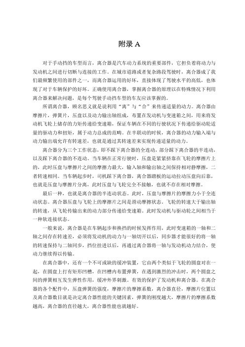
分离杠杆的运动干涉及防止措施
Release lever movement interface and control
离合器分离时 压盘 pressure disengagement plate 压盘的运动 pressure plate moving 分离杠杆的运动 release lever moving 干涉interface 干涉 防干涉interface control。 防干涉 。
离合器Clutch 离合器
engine Clutch transmission Drive axles
§12.1 概 述 Overview
一、功用Function: 功用 : 1.使发动机与传动系逐渐接合,保证汽车平稳起步。To 使发动机与传动系逐渐接合,保证汽车平稳起步。 connect engine to power train gradually to move the vehicle smoothly. 2.暂时切断发动机与传动系的联系,便于发动机的起动和 暂时切断发动机与传动系的联系, 变速器的换档。 变速器的换档。To cut off the linkage between engine and power train to start engine and shift easily. 3.限制所传递的转矩,防止传动系过载。To limit the 限制所传递的转矩,防止传动系过载。 delivery torque to prevent engine from overload.
Disengagement; ; Engaging procedure。 。
接合状态 Engagement/connection position
式中: 式中: μ-摩擦系数 摩擦系数friction coefficient; ; Z-摩擦面数 摩擦面数number of friction side; ; FQ-压盘对摩擦片的总压紧 力total pressure force; ; Rc-摩擦片的平均摩擦半径 friction radius; ; β-储备系数 储备系数reserve factor; Μemax—发动机的最大有效 发动机的最大有效 转矩。 转矩。Max. effective torque
离合器技术发展史外文文献翻译、中英文翻译、外文翻译

Clutch technology development historyIn the 100 years of the history of the development of automobile, almost all of the components in terms of technology development have experienced great changes: reliability, production cost, convenient maintenance, energy saving and emission reduction and so on, have been and will always be the automotive industry in the pursuit of goals, these goals for Automotive engineers continue to develop solutions newer and better.Technically, it was not until 1910 that the reciprocating piston internal combustion engine was significantly more efficient than cars and electric vehicles. In 1902, a gasoline engine car first broke the record of the highest speed, and before that, the highest speed record has been created by steam cars and electric cars. Supporters of the three different drivers of the car have been racing and racing for the first ten years of twentieth Century to break the record.Liquid fuel to drive the car to "steam and electric vehicles" (steam and electric vehicle supporters habit called) has a very prominent advantage is its nearly ideal torque characteristics, they do not need a clutch, does not need the transmission, so it is easy to operate, less failure, easier to maintain. Since the reciprocating piston internal combustion engine can only output torque when it reaches a certain speed, it is necessary to have a separate joint between the engine and the transmission. Gasoline engines need to use the clutch engagement function to start the car, because only when the engine reaches a certain speed, the output torque. In addition to the engagement of the clutch, the clutch's separation function is also important because it is free to move in the vehicle. In view of the complexity of the related problems, there is no clutch engagement function in many small car design structures in the early stage.Origin of clutchThe working principle of first generation clutch from the early use of mechanical equipment factory industrial society. Through the analogy of belt transmission, a kind of flat belt is introduced into the car. By means of the tension of the belt pulley, the belt transfers the output torque of the engine to the driving gear, and when the belt is relaxed by adjusting the roller, the belt slipping is equivalent to the separation of the clutch. Because this process causes the abrasion of the belt is too fast, people will adopt a new method: install a drive pulley with the same size of the idler wheel, by pulling the lever, the drive belt from the idler wheel to drive wheel.This belt drive is a disadvantage, low efficiency, easy to wear, especially the transfer of power shortage in rainy days; on the other hand is the requirement of transmission gear to increase engine torque to constantly improve, this has prompted engineers to explore better to replace the clutch.The result is clutch invented a variety of people, including modern clutch pioneer -- Based on the principle of friction clutch. This is a disc located at the end of the crankshaft and connected to another stationary disk. When the two disks are in contact, the friction is produced, and the stationary disk begins to rotate. With the increase of the clamping force, the driving disc drives the driven disc to make thespeed of the driven disk continuously improve until the transmission is working normally, and the two disks rotate at the same speed. Before the two disks are fully engaged, they are in contact with one side and slip, and most of the kinetic energy from the engine is converted into heat. This structure can meet the following two requirements: on the one hand gently gently engage in when starting a car engine will stall, it will not cause the transmission jitter; on the other hand, the clutch can be nondestructively torque to the transmission.Clutch pedal to work through. Press the clutch pedal, pull the conical seat ring through the separation fork, release the spring, so as to separate the clutch.Early clutchIn 1889, Daimler's steel wheel car had used the basic form of this design principle: equipped with a tapered / bevel friction clutch. The freely movable conical disc is located on the transmission shaft, and the flywheel with a tapered groove on the crankshaft can be firmly engaged. The coil spring presses the conical disc into the tapered groove of the flywheel and the clutch is engaged; the foot pedal can be stepped down, and the conical disc can be pulled back by separating the sleeve and the spring, thereby separating the clutch and interrupting the power transmission. Originally used as a conical disc friction surface material, but was quickly replaced the leather. The latter is soaked in castor oil, can prevent moisture, oil / fat. The utility model has the advantages that the utility model can be automatically adjusted, and the input shaft of the transmission is not stressed. On the one hand, the wear of friction plate is too fast, the replacement is too complex, after the friction in the design of the friction plate spring pin or drive to improve. On the other hand, the flywheel and clutch cone is too large, so that the inertia torque is larger and the clutch is much slower than the required separation process.To solve the above problems, around 1910s, with another clutch brake or brake transmission, it through a second foot pedal to play a role, usually the second pedal and the clutch pedal are connected together, and are located in the rear of the pedal shaft.When changing the speed, many drivers are used to make the clutch slipping and not shift, then the flywheel heating degree is more serious than only by the tapered disc friction cone disc by friction layer of leather to heat. After a long period of long-distance driving, due to the thermal expansion of the flywheel, the cone may be more engaging with the flywheel, but when the flywheel temperature drops, it is difficult to separate the cone from the flywheel.Until the first World War period, metal friction began to spread up. Previously, people also experimented with other different materials, such as NAG company designed a camelhair cone disc thin steel sheet pressing, and fitted with a fanlike blade used for cooling, it engages in the two part, bolted to the flywheel on the leather ring line. The two part of the structure allows the free movement of the leather wire ring, thereby simplifying the clutch maintenance and reducing the number of times the clutch is stuck.Daimler motor company has developed an open friction clutch with an aluminum cone. In order to separate the soft, the oil on the friction layer.Because of the simple structure, the cone disc clutch has been the dominant position in the whole 1920s. Cylindrical friction surfaces are not accepted because of their poor operating performance. Only cylindrical clutch spring clutch with the evolution version, due to its creative design, only by Daimler in late nineteenth Century early twentieth Century with the Mercedes Benz car, and continued until the first world war.The traditional single disc dry clutchIn spring clutch, a wearable spiral spring, and the input shaft of the transmission drum end, mounted in the recess of the flywheel. One end of the spiral spring plate is connected with the flywheel, and the other end is fastened on the spring cover. The clutch pedal presses the spring plate, the leaf spring is more and more tight around the drum shape (automatic enhancement), and drives the transmission input shaft. Only a small force can compress the spring and make the clutch soft.About the development of spring clutch in the Daimler company at the same time, Professor Hele-Shaw from the UK also completed the test of multi disc clutch, which is also considered a precursor to the current traditional single disc dry clutch. One of the key advantages of the "Weston" clutch, which can be produced on a large scale, is that it has a large area of friction and can be continuously engaged in a smaller mounting space.In multi disc clutch, flywheel connected to the drum cover, and according to the outer shape of the coil inside the slot, and allow the disc to rotate with the crankshaft and flywheel, and longitudinal movement. The same number of concave disks are positioned in the center of the hub, and the hub is connected to the clutch shaft. These disks can be moved longitudinally along the clutch shaft on the hub. During the installation, the internal and external driven plates of the clutch are alternately connected to form a set of disks, such as the active and driven disks are always connected with each other.The driven disc work like this: start the bronze plate is always facing the steel wheel, and the spiral spring under the pressure plate is pressed together. In this way, all disks are continuously engaged. The gradual increase in the friction force allows the clutch to engage very softly. With the decrease of the spring pressure, the driven plate is separated, and the supporting part of the driving plate starts to bend from the plane of the driven plate. By changing the number of driven disc pairs, the clutch can be adjusted to fit the output power of each engine.Multi disc clutch for oil / gasoline, can also be dry. The dry type is special, and the friction layer is riveted by rivets. Multi disc clutch, especially the oil bath type multi disc clutch, its biggest drawback is a certain degree of hysteresis, which can only be part of the separation, resulting in difficult shift.After several years, single disc clutch has eliminated the cone disc and multi disc clutch. De Dion and Bouton are the first to realize that a single disc clutch is the future direction of the clutch. With the appearance of Ferodo asbestos friction sheet, clutch technology has made great progress. Asbestos friction sheet has been used since 1920s, until it is replaced by non asbestos friction sheet. The advantage of a single disc dry clutch is obvious: the lower drive disc mass allows it to stop fasterafter separation, thus making it easier to shift gears - a complete farewell to the transmission brake structure.The original structure single disc dry relatively complex. The clutch housing is bolted to the flywheel and the clutch cover is bolted to the clutch housing. The clutch cover with the spring to the inner side of the compression lever is transferred from the intermediate plate through the friction disc, and the torque from the flywheel is transmitted to the transmission. The friction disc is connected to the connection or transmission input shaft by the driver. The clutch is separated and joined by means of a sliding ring plate that allows the tapered disc to move forward and backward. Each side of the cone disc acts on the separating lever correspondingly, and the separating lever is operated by a spiral spring, and is pressed or separated. Due to the fact that the cone is rotating and the sliding ring is stationary, it needs to be lubricated periodically.The spiral spring clutch pressing force provided by the spring, won the people's recognition. At first, the coil spring is placed in the middle of the test, but only a few smaller spiral or spiral spring along the outer ring of the clutch housing arrangement of the structure to be mass production. The release lever compresses the coil spring by a separate bearing which can move freely on the transmission input shaft to separate the clutch. The pressing force can be due to the use of different spring and change, but there is a fatal disadvantage, namely with the increase of engine speed, a spiral spring located in the outer ring of the pressure plate, due to the centrifugal force to the spring cover direction to the outward pressure, the friction between the spring and the cover, the pressing force performance curve change.As the engine speed increases, the clutch becomes heavier and heavier. In addition, the separation bearing used to separate the lever has been in a state of pressure, so that it and the clutch cover is easy to wear, especially in the high speed of the engine gear shift, will soon wear.The birth of diaphragm clutchIn order to solve the problems of these systems, we developed a diaphragm spring clutch diaphragm spring clutch, the research laboratory was born in 1936 of general motors, and mass production in late 1930s in the United states. In Europe, after the Second World War, people began to be familiar with the diaphragm spring clutch through the American General Company military truck, and in the middle of 1950s in a number of single European models. Porsche 356, BMW Goggomobil 700 and DKW Munga is the first batch of the diaphragm spring clutch is equipped with German cars. Diaphragm spring clutch mass production began in 1965 with the Opel Rekord models.Because of the diaphragm spring clutch can be balanced and symmetrical rotation, so it is not affected by the engine speed. The diaphragm spring clutch was a success in 1960s, when the camshaft top mounted high speed engine (Glas, BMW, Alpha Romeo) was widely used to replace the camshaft engine. By the end of the 1960s, almost all car manufacturers have adopted diaphragm spring clutch.Here need to emphasize is: let LuK in diaphragm spring clutch mass production, played a crucial role. Replace all the separate lever helical spring system withdiaphragm spring, brings a lot of advantages: simple structure, constant pressing force, installation space is relatively high pressing force only needs a relatively small (very important for transverse engine) and is not affected by the impact of engine speed. Because of these characteristics, almost all of the modern use of diaphragm spring clutch, and its application in the multi-function car is also more and more - has been the use of spiral spring clutch.With the development of correspondingly, clutch disc has been optimized. Reciprocating piston internal combustion engine changes in the speed and torque generated by the vibration of the crankshaft, clutch, transmission input shaft to the transmission, resulting in noise and severe gear wear. In the modern automobile, the weight of the flywheel and the vehicle is increasing, so the clutch driven disc with the torque damper and the wave spring is developed.Long time operated clutch needs a strong thigh, because the pedal force must be transferred through the connecting rod or shaft / cable. With the application of the clutch and the hydraulic separation mechanism in 1950s in 1930s, the driving comfort has been improved.To try different clutch automatic clutch to make operation more simple: in 1918, Wolseley first proposed the concept of electromagnetic clutch. In the early 1930s, the French Cotal company produced a luxury car with a magnetic clutch, a pre selector transmission. The most famous is the centrifugal clutch to adjust the clamping force by centrifugal force and automatic clutch, such as Saxomat (Fichtel & Sax company), LuKomat (LuK), Manumatik (Borg & Beck) and Ferlec (Ferodo).离合器技术发展史在100多年的汽车发展史中,几乎所有的零部件在技术方面都经历过巨大的发展变化:可靠性、生产成本、维护便利性、节能减排性等,都已经且将一直成为汽车行业的追求目标,这些发展目标要求汽车工程师们不断地开发出更新更好的解决方案。
中英文文献翻译—离合器的简单介绍
附录A对于手动挡的车型而言,离合器是汽车动力系统的重要部件,它担负着将动力与发动机之间进行切断与连接的工作。
在城市道路或者复杂路段驾驶时,离合器成了我们最频繁使用的部件之一,而离合器运用的好坏,直接体现了驾驶水平的高低,也体现了对于车辆保护的好坏。
正确使用离合器,掌握离合器的原理以在特殊情况下利用离合器来解决问题,是每个驾驶手动挡车型的车友应该掌握的。
所谓离合器,顾名思义就是说利用“离”与“合”来传递适量的动力。
离合器由摩擦片,弹簧片,压盘以及动力输出轴组成,布置在发动机与变速箱之间,用来将发动机飞轮上储存的力矩传递给变速箱,保证车辆在不同的行驶状况下传递给驱动轮适量的驱动力和扭矩,属于动力总成的范畴。
在半联动的时候,离合器的动力输入端与动力输出端允许有转速差,也就是通过其转速差来实现传递适量的动力。
离合器分为三个工作状态,即不踩下离合器的全连动,部分踩下离合器的半连动,以及踩下离合器的不连动。
当车辆在正常行驶时,压盘是紧紧挤靠在飞轮的摩擦片上的,此时压盘与摩擦片之间的摩擦力最大,输入轴和输出轴之间保持相对静摩擦,二者转速相同。
当车辆起步时,司机踩下离合器,离合器踏板的运动拉动压盘向后靠,也就是压盘与摩擦片分离,此时压盘与飞轮完全不接触,也就不存在相对摩擦。
最后一种,也就是离合器的半连动状态。
此时,压盘与摩擦片的摩擦力小于全连动状态。
离合器压盘与飞轮上的摩擦片之间是滑动摩擦状态。
飞轮的转速大于输出轴的转速,从飞轮传输出来的动力部分传递给变速箱。
此时发动机与驱动轮之间相当于一种软连接状态。
一般来说,离合器是在车辆起步和换挡的时候发挥作用,此时变速箱的一轴和二轴之间存在转速差,必须将发动机的动力与一轴切开以后,同步器才能很好的将一轴的转速保持与二轴同步,挡位挂进以后,再通过离合器将一轴与发动机动力结合,使动力继续得以传输。
在离合器中,还有一个不可或缺的缓冲装置,它由两个类似于飞轮的圆盘对在一起,在圆盘上打有矩形凹槽,在凹槽内布置弹簧,在遇到激烈的冲击时,两个圆盘之间的弹簧相互发生弹性作用,缓冲外界刺激。
中英文文献翻译-离合器的简单介绍

附录AThe clutchThe clutch is a device to engage an disengage power from the engine, allowing the vehicle to stop and start.The diaphragm spring clutch consists of the clutch plate , the diaphragm spring , the pressure plate , the tortional vibration damper and the cover.When the clutch and pressure plates are locked together by friction , the clutch shaft rotates with the engine crankshaft . Power is transferred form the engine to the transmission , where it is routed through different gear ratios to obtain the best speed and power to start and keep the vehicle moving.The clutch plate or driven member consists of a round metal plate attached to a splined hub. The outer portion of the round plate is covered with a friction material of molded or woven asbestos and is riveted or bonded to the plate. The thickness of the clutch plate and/or facings may be warped to give a softer clutch engagement . Coil springs are often installed in the hub to help provide a cushion cushion against the twisting the twisting force of clutch engagement . The splined hub is mated to (and turns) a splined transmission shaft when the clutch is engage.A pressure plate or "driving member" is bolted to the engine flywheel and a clutch plate or "driven member "is located between the flywheel and the pressure plate. The clutch plate is splined to the shaft extending from the transmission to the flywheel, commonly called a clutch shaft or input shaft.附录B离合器离合器是一个传递和切断发动机动力使汽车可停止和前进的装置.膜片弹簧离合器由:从动盘,膜片弹簧,压盘,扭转减震器,离合器盖,操纵机构组成。
中英文文献翻译-离合器
附录 AClutch between engine and transmission installed in the car to travel from the start the whole process, often need to use the clutch. Its role is to make the engine and transmission can be gradually between the joint, thus ensuring a smooth start car; temporarily cut off the link between the engine and transmission to shift at the time of shift and reduce the impact; When the car when emergency braking from Separate role in preventing the transmission and other drive system overload, play a protective role.Clutch similar to the switch, splice or break away from the power transmission and, accordingly, have any form of auto clutch, but the form is different.By the friction plate clutch, springs, pressure plate and the power output shaft composed, arranged between the engine and gearbox, the engine flywheel to the torque is passed to the stored transmission, to ensure that vehicles in different driving conditions passed to the driver Wheel driving force and the right amount of torque, is the scope of the powertrain. In the half-time of linkage, clutch and power input power output allowed speed difference, that is, the speed error to achieve through its transfer an appropriate amount of power. Clutch is divided into three work status, ie the clutch all connections, some of the half clutch linkage and the clutch is not linked.When a vehicle in normal driving, the pressure plate is jammed against the friction plate on the flywheel, pressure plate and friction plate at this time the friction between the largest between the input shaft and output shaft remained relatively static friction, both the same speed . When the vehicle is started, the driver depresses the clutch, clutch pedal movement by pulling back pressure plate, which is the separation of the pressure plate and friction disc, pressure plate and flywheel at this time no contact, but also the relative friction does not exist. Last one, that is, half of the clutch linkage status. At this point, the pressure plate and friction disc friction less than the full-linked state. Clutch pressure plate and flywheel friction plate on the sliding friction between the state. Flywheel speed is greater than the output shaft speed, transmission out of the power from the flywheel to the transmission part of the pass. Between the engine and driving wheels at this time is equivalent to a soft connection status.In general, the clutch and the shift in the vehicle when starting to play a role, this time a transmission shaft and the speed difference between the two shafts, engine power must be cut with a shaft after the synchronizer can be very good a shaft speed will be kept synchronized with the second axis, gear hanging up after, and then through the clutch shaft and the engine power will be a combination of the power continue to be transmitted. In the clutch, there is an essential buffer device, which consists of two similar to the flywheel with the disc, the disc hit a rectangular groove, the groove arrangement of the spring, in the face of fierce shock between the two disc springs between the elastic effect, buffer external stimuli. Effective protection of the engine and clutch. Various parts of the clutch, pressure plate spring strength, friction coefficient of friction plate, clutch diameter, location, and the clutch friction disc clutch performance is to determine the number of key factors, the greater the stiffness of the spring, the higher the friction coefficient of friction plates, the larger the diameter of the clutch, clutch performance, the better.附录 B离合器安装在发动机与变速器之间,汽车从启动到行驶的整个过程中,经常需要使用离合器。
中英文文献翻译—离合器工作原理
附录How Clutches WorkIf you drive a manual transmission car, you may be surprised to find out that it has more than one clutch. And it turns out that folks with automatic transmission cars have clutches, too. In fact, there are clutches in many things you probably see or use every day: Many cordless drills have a clutch, chain saws have a centrifugal clutch and even some yo-yos have a clutch.CIn!cp I山g?e CgIIeL入D!g?Lg山 o\ cgL 2poM!u? cIn!cp Iocg!!ou. eee 山oLe cIn!cp !山g?e2In this article, you'll learn why you need a clutch, how the clutch in your car works and find out some interesting, and perhaps surprising, places where clutches can be found. Clutches are useful in devices that have two rotating shafts. In these devices, one of the shafts is typically driven by a motor or pulley, and the other shaft drives another device. In a drill, for instance, one shaft is driven by a motor and the other drives a drill chuck. The clutch connects the two shafts so that they can either be locked together and spin at the same speed,or be decoupled and spin at different speeds.In a car,you need a clutch because the engine spins all the time,but the car's wheels do not. In order for a car to stop without killing the engine, the wheels need to be disconnectedf rom the engine somehow. The clutch allows us to smoothly engage a spinning engine to a non-spinning transmission by controlling the slippage between them.To understand how a clutch works, it helps to know a little bit about friction, which is a measure of how hard it is to slide one object over another. Friction is caused by the peaks and valleys that are part of every surface -- even very smooth surfaces still have microscopic peaks and valleys. The larger these peaks and valleys are, the harder it is to slide the object. You can learn more about friction in How Brakes Work.A clutch works because of friction between a clutch plate and a flywheel. We'll look at how these parts work together in the next section.Fly Wheels,Clutch Plates and FrictionIn a car’s clutch, a flywheel connects to the engine, and a clutch plate connects to the transmission. You can see what this looks like in the figure below.When your foot is off the pedal, the springs push the pressure plate against the clutch disc, which in turn presses against the flywheel. This locks the engine to the transmission input shaft, causing them to spin at the same speed.Pressure plateThe amount of force the clutch can hold depends on the friction between the clutch plate and the flywheel, and how much force the spring puts on the pressure plate. The friction force in the clutch works just like the blocks described in the friction section of How Brakes Work, except that the spring presses on the clutch plate instead of weight pressing the block into the ground.W h en the clutch pedal is pressed, a cable or hydraulic piston pushes on the release fork, which presses the throw-out bearing against the middle of the diaphragm spring. As the middle of the diaphragm spring is pushed in, a series of pins near the outside of the spring causes the spring to pull the pressure plate away from the clutch disc (see below). This r eleases the clutch from the spinning engine.Common ProblemsFrom the 1950s to the 1970s, you could count on getting between 50,000 and 70,000 miles from your car's clutch. Clutches can now last for more than 80,000 miles if you use them gently and maintain them well. If not cared for, clutches can start to break down at 35,000 miles. Trucks that are consistently overloaded or that frequently tow heavy loads can also have problems with relatively new clutches.Photo courtesy Carolina MustangClutch plateThe clutch only wears while the clutch disc and the flywheel are spinning at different speeds. When they are locked together, the friction material is held tightly against the flywheel, and they spin in sync. It's only when the clutch disc is slipping against the flywheel that wearing occurs. So, if you are the type of driver who slips the clutch a lot, you'll wear out your clutch a lot faster.Sometimes the problem is not with slipping, but with sticking. If your clutch won't release properly, it will continue to turn the input shaft. This can cause grinding, or completely p revent your car from going into gear. Some common reasons a clutch may stick are: Broken or stretched clutch cable - The cable needs the right amount of tension to push and pull effectively.Leaky or defective slave and/or master clutch cylinders - Leaks keep the cylinders from building the necessary amount of pressure.Air in the hydraulic line - Air affects the hydraulics by taking up space the fluid needs to build pressure.Misadjusted linkage - When your foot hits the pedal, the linkage transmits the wrong amount of force.Mismatched clutch components - Not all aftermarket parts work with your clutch.depress fully. If you have to press hard on the pedal, there may be something wrong. Sticking or binding in the pedal linkage, cable, cross shaft, or pivot ball are common causes. S o metimes a blockage or worn seals in the hydraulic system can also cause a hard clutch. Another problem associated with clutches is a worn throw-out bearing, sometimes called a clutch release bearing. This bearing applies force to the fingers of the spinning pressure plate to release the clutch.If you hear a rumbling sound when the clutch engages,you might have a problem with the throw-out.Types of ClutchesThere are many other types of clutches in your car and in your garage.An automatic transmission contains several clutches. These clutches engage and disengage various sets of planetary gears. Each clutch is put into motion using pressurized hydraulic fluid. When the pressure drops, springs cause the clutch to release. Evenly spacedridges, called splines, line the inside and outside of the clutch to lock into the gears and the clutch housing. You can read more about these clutches in How Automatic Transmissions Work.An air conditioning, compressor in a car has an electromagnetic clutch. This allows the compressor to shut off even while the engine is running. When current flows through a magnetic coil in the clutch, the clutch engages. As soon as the current stops, such as when you turn off your air conditioning, the clutch disengages.Most cars that have an engine-driven cooling fan have a thermostatically controlled viscous clutch -- the temperature of the fluid actually drives the clutch. This clutch is positioned at the hub of the fan, in the airflow coming through the radiator. This type of clutch is a lot like the viscous coupling sometimes found in all-wheel drive cars. The fluid in the clutch gets thicker as it heats up, causing the fan to spin faster to catch up with the engine rotation. When the car is cold, the fluid in the clutch remains cold and the fan spins s lowly, allowing the engine to quickly warm up to its proper operating temperature.Many cars have limited slip differentials or viscous couplings, both of which use clutches to help increase traction. When your car turns, one wheel spins faster than the other, which makes the car hard to handle. The slip differential makes up for that with the help of its clutch. When one wheel spins faster than the others, the clutch engages to slow it down and match the other three. Driving over puddles of water or patches of ice can also spin your wheels. You can learn more about differentials and viscous couplings in How Differentials Work.Gas-powered chain saws and weed eaters have centrifugal clutches, so that the chains or strings can stop spinning without you having to turn off the engine. These clutches work automatically through the use of centrifugal force. The input is connected to the engine crankshaft. The output can drive a chain, belt or shaft. As the rotations per minute increase, w eighted arms swing out and force the clutch to engage. Centrifugal clutches are also often found in lawn mowers, go-karts, mopeds and mini-bikes. Even some yo-yos are m anufactured with centrifugal clutches.C lu tches are valuable and necessary to a number of applications. For more information on clutches and related topics, check out the links on the following page.离合器工作原理如果您驾驶手动变速箱的汽车,您可能会惊讶地发现,它有一个以上的离合器。
中英文文献翻译-汽车离合器技术的新发展
附 录录1Clutch of new developments in technologyAbstract: in recent years car design and manufacturing technology progress for all to see. In order to further improve product performance, prolong service life, common mechanical clutch technology is also produced a remarkable change. No matter from structural characteristics, product process performance, or control technology, mechanical clutch of technological progress in some extent reflects the development of design concepts, and possible technology trends in the future.Keywords: clutch; Technology development1, introductionIn car technology rapid development today, especially with the electronic technology in cars, the extensive application of vehicle drivetrain is had great progress, as an important part of the transmission of the clutch assembly force transmission, the burden of reducing vibration and prevent system overload very important role. To make sure that the power transmission and reliable, separate thoroughly, combined with soft, damping good, small volume, light weight, easy, long service life, making the clutch product either cash from the performance, structure, or manufacturing mode and control, in the occurrence of a lot of change. They greatly optimized clutch all aspects of performance, to some extent look, these changes are also reflected the development direction of the clutch.2, engine flywheel new structureAs one of the flywheel storage components engine, is also part of the clutch initiative. As the car transmission belong to multi-freedom torsional vibration system, whether the incentive and transmission system, or the associated force vibration type and the coupling vibration with other statements are very complex. In order to adapt to car driving conditions of vibration and noise reduction of reducing the need, making cars, ride comfort the role of torsional shock absorber is extremely important. It should be able to adjust the system inherent frequency, the system mainly low-order resonance critical speed remove common, also need to use speed range, still need to decrease amplitude damping of transmission system can reduce idle noise, ease the impact of the special case load. Previous clutch platen set on by a twist of shock absorber, decorate a space place is restricted, shock absorber work reverse Angle small, torsion stiffness big, capacity small, springs, and therefore not guarantee the intensity of vibration reduction is limited.In recent years, the emergence of a reverse damping characteristics and performance to price are ideal double quality flywheel structure. The flywheel by primary flywheel, reverse shock absorber and subprime flywheel composition, among them, the primary flywheel on one hand we should provide for the shock absorber and clutch installation space, on theother hand also with appropriate rotational inertia insure a car, and reduce passed back starting the amplitude. Generally, double quality flywheel adopts with circular arc shape along the spiral spring primary flywheel outer periphery decorate way, in limited circumstances decorate a space, the arrangement to obtain larger primary flywheel rotational inertia. The inertia and the clutch after brief increase engine speed fluctuation of related parts, shorten their service life. To avoid the above phenomenon, often need additional Settings special damping, such, can increase the difficulty and cost of product development. Because the engine of the car front front drive type of transmission installation space is limited, so this kind of structure in FF type cars to the promotion. Meanwhile, this kind of decorate spring along the circumference, due to high speed double quality flywheel centrifugal role, spring wear when, or even produces broken.Using radial layout springs can improve the double quality flywheel of the above mentioned products defect. It consists of primary flywheel, 3 ~ 4 springs box, damping dish and subprime flywheel composition. Because the suspension spring box of radial layout, the primary flywheel rely on four posts the muscles of rib takes form enough flywheel stiffness and produced similar with traditional flywheel inertia.This kind is decorated in a small space to with smaller quality to gain the maximum rotation inertia, help reduce the assembly structure, the axial dimensions for subprime flywheel and clutch decorate a space make more. Its damping device by a wear-resisting plastic gasket, a belt of steel plate and a slot disc spring washers constitute, they set in damping plate, rely on damping disc hole flanging positioning and compaction, the damping disk with primary flywheel riveted by the subprime, plastic gasket flywheel slot drive. Practice proves that the double quality than ever, this structure can be the flywheel in a limited space get quite good vibration reduction.Engine for the job, usually by the flywheel, inertia and the clutch clutch disc provides together. The ideal flywheel structure should be to offer the same, and ensure enough inertia structure stiffness premise to minimize the flywheel quality, stamping steel way to replace traditional casting can obtain the flywheel ways to produce the effect. Change the pressure by casting lron yuntechtc ring, start toothed ring and steel blunt system drivers disk of three parts. In the ring gear driving plate welding, pressure rings and drivers disk riveting, pressure ring of moment of inertia of the subject constitutes a flywheel, and provide for the clutch friction surface and heat conduction. Drivers disk improve enough flywheel stiffness, and using laser welding and clutch cover, this is connected to this structure forms of changescan be compared to traditional iron flywheel reduce quality 5% ~ 10%. USES the steel plate stamping type flywheel, and clutch cover and flywheel connections between after replacing bolt connection with welding, reducing the number and machinery manufactured parts, which reduces the production cost. The foregoing radial layout springs double quality can use this stamping yuntechtc for structure form, reducing axial dimensions []17. 3, clutch discClutch platen design of the main contradiction is facing, on one hand, hope to have as played platen diameter, in order to obtain the good preach torsional characteristic, reducing friction slices wear quantity and improve the service life, on the other hand, hope the decrease of the platen as possible, so as to shorten the rotational inertia of the variable transmission shift, ensure the synchronization time of smooth, transmission clutch platen ontology conscious drops, and therefore made wavy often difficult to coordinate the contradiction. When using triangle groove platen ontology structure, while keeping the original way wavy platen ontology has the axial elastic properties at the same time, because of its large on the plane can be formed, enough to make its and friction slices adhesive is used to connect the replacement of traditional riveting, so that in friction chip will not need the thickness of the steel back to reserve rivet, so clutch friction slices thickness, which can reduce the platen axial dimensions, and can be reduced by 10% of inertia can reduce nearly 25%. In other words, keep the premise of inertia unchanged, possible will platen diameter increases, so can the arrangement for torsional shock absorber, let a space when damper spring job increase, the rigidity of the shock absorber in diameter can be reduced greatly, increasing the space for setting also provides an ideal damping components fundamental conditions. On the other hand, because platen diameter increases, the optimization of diaphragm spring separation means it can obviously reduce leverage than the load bearing separation.Using triangle groove platen ontology and friction piece of adhesive technology, still can make clutch friction slices surface pressure distribution, and more uniform can improve the service life of friction slices.4, clutch diaphragm springUsing the diaphragm spring of a nonlinear elastic properties, can increase the ability of clutch abrasion resistance. Usually, can pass the clutch when installation, adjustment diaphragm spring axial position, to keep the spring of compaction force, but due to the manufacturing process of previous position error is quite large, so often wasted spring this portion of elastic energy, enables the abrasion resistance ability get full play. When the clutch cover and flywheel connection with the above welding way to finish, the clutch assembly may allow such position when the adjustment, thus, the corresponding clutchscratch-resistant ability can improve the 4% ~ 30%.To improve the ability to change its antiwear properties, but also can the diaphragm spring is reinforced by controlling method of separation means and the rib disc supporting ring approach to getting.[]175, clutch control systemAutomatic transmission in cars growing popularity of today, due to its lack of transmission efficiency of cars, and motorists feel lost control, makes mechanical clutch still has wide market. Along with the computer technology and the rapid development of modern control technology has to clutch may reality automatic control, automatic clutch management system (CMC) is the product of this idea. The driver speaking, clutch automatic control system is that it is the most obvious advantage of cancelled the clutch pedal, thus improve the driving comfort, whether in the city the frequent change of traffic environment, or in the ramp, its advantages are started is quite clear. Meanwhile, in order to reduce the transmission low noise and vibration, CMC is likely to clutch real-time control of sliding, all these can improve automobile driving safety. Although the automatic transmission can also play the same role in price, but the CMC, fuel efficiency, engine braking and rapid response, etc but again the obvious advantage. In addition, it has no peristalsis phenomenon, and can make control shift timing. Drivers On the other hand, for car itself, because the CMC reduced because the actual driving quite frequent false operation produces drivetrain stress, therefore, can reduce the transmission and its transmission parts design dimensions, in general driving conditions, electronic control ensures the accuracy and speed than artificially operation circumstance clutch of wear small, long service life.CMC consists of three parts: namely is used to identify the driver intention and the clutch, the transmission working state of sensors,Clutch actuators and electronic control unit, drivers shift HuanDangGan movements and intention through the release of the accelerator pedal to identify, this requires signal judge strategy and control must be very quick, to avoid the feeling of driver produce shift block, when pilots inadvertently tinkering with the transmission system when rod may not false action. In addition, the CMC through the engine speed, the transmission input shaft speed and throttle position signal to clutch slip for mind control, which can eliminate the car driving common vibration and noise. Such as a limit control to prevent slip in 1 and 2, block small throttle low-speed driving, the car slightly tilted forward, generating about 1Hz very uncomfortable zitterbewegung, through in the clutch of transient torsional direction change quickly, to eliminate the separation clutch in clutch under the condition of incomplete combinations, when pilots alternate relaxation and trample accelerator pedal, because thetransmission torque change to the sharp produced recoiling sickening crash; or depressing Through the precise relative slip between 50 ~ 100rpm control, can eliminate in high-grade, high and low speed conditions when the engine driving torque values in the passenger cabin can smell the low-frequency resonance produced, and when the transmission in 2 ~ 3 block,engine speed 12 ~ 2500rpm and high load, the transmission possible beats noise; Through the separation clutch, convenient when the elimination of the idle will clutch and neutral transmission combine, engine torque peak in the transmission of idle speed noise produced. The key is to prevent vibration noise sensitivity and accuracy, this system requirements system has high control ability, rely on modern computer and hydraulic control technology has been possible this some.[]186, closingBy adopting a new design concept, can make clutch axial dimensions is much shorter, platen diameter increases, power transmission more reliable, clutch capacity increases, separation bearing load is reduced, torsion vibration reduction improve, processing manufacturing easier, lower cost, service life can be extended 50% and than before can be expected, along with the automatic control technology mature gradually perfect, clutch control mode will also continue to rapid development.附 录录 2汽车离合器技术的新发展摘要:近年来汽车设计和制造技术的进步有目共睹。
中英文文献翻译—一些离合器的简介
附录A Little Brief Introduction Of ClutchNowadays the pioneers of the clutch disc, clutch disc is more pieces of it until 1925 later. The multi-gear clutch main advantage is that car started the clutch engagement is no impact on the smooth. Early in the design, layout design, according to slice pairs of a steel plate with a bronze blanks. Using the friction pair of pure metal, put them in oil, can achieve more satisfactory performance.As the power to combustion in mechanical transmission automobiles, clutch is as an independent assembly. The clutch is usually served in the engine and transmission, the active part between connected with engine flywheel, driven and transmission. Various types of cars for widespread adoption of friction clutch, in fact, is a kind of depend on their part, driven to relay the friction between the power and the separation. The major function of the clutch is cut off and the realization of the engine and transmission, to ensure smooth, stable car When the shift in the engine and transmission of separation, reduce transmission gear shift between the impact, Work in the dynamic load is larger, can limit the transmission of maximum torque, in order to prevent the transmission parts of a damaged by overload, Reducing effectively the transmission of the vibration and noise.In the early development of clutch structures, the most successful conical clutch. It was the prototype design in 1889 German Daimler company production of steel wheel on the car. It is to make the engine flywheel hole taper as clutch active. The taper clutch scheme continues to the middle of the twentieth century, when the manufacture, cone-shaped clutch friction relatively simple, easy to repair. It was used LuoMao friction material, leather belt, etc. Then have been hoof - drum clutch, its structure in the solid-bowl clingy reaches hoof. Hoof - drum clutch friction components with wood, leather belt is such, shoe - drum clutch weight is light cone clutch. Whatever tapered clutch or hoof - drum clutch, easy to cause the separation is not complete appear even Lord, follower cannot separate self-locking phenomenon.Years of practical experience and technical improvement makes people tend to preferred dry friction clutch single chip, because it has driven part of inertia, good heat, simple structure, convenient adjustment, compact size, etc, but also because completely in structure, already cantake action to smooth, so now junction disc is widely used in large, medium and small various models.Now monolithic dry type clutch in structural design is quite perfect. Using the axial elastic platen, improve the clutch of comfort. The clutch platen assembly installed in reverse, prevent the transmission system of shock of torsional resonances, reduced the transmission system of noise and load.As the car comfort requirements, clutch in original basis has been obtained by car, by continuously improved by increasing the quality of the flywheel has double shock absorber, can turn better reduce transmission noise.Due to heavy clutch, commercial, engine power tends to large-scale increasing, but the size of the space increased clutch allows the use of limited, clutch, cool, increase conditions to improve ability, preaching clutch torsion life-span, simplify the operation has become the development trend of the heavy clutch. In order to improve the ability of torsion, in heavy vehicles can be used on double dry type clutch. Theoretically, in the same radial dimensions, biplate clutch torsion ability and the service life is 2 times of single chip. But other objective factors, the actual effects of low value than others.In recent years, the wet clutch on technology improvement, some heavy cart in abroad and start using multiple wet clutch. Compared with dry type clutch, due to the use of the pump are forced cooling, friction surface temperature is lower than 93 degrees Celsius (not), therefore, long time also does not start sliding friction loss. Refer to the information at home and abroad were told that this clutch can use dry type clutch of 5-6 times, but the advantages of the wet clutch play must be in a temperature range, more than it can achieve a temperature range will play a negative effects. Now this technology is not perfect.一些离合器的简介现今所用的盘式离合器的先驱是多片盘式离合器,它是直到1925年以后才出现的。
- 1、下载文档前请自行甄别文档内容的完整性,平台不提供额外的编辑、内容补充、找答案等附加服务。
- 2、"仅部分预览"的文档,不可在线预览部分如存在完整性等问题,可反馈申请退款(可完整预览的文档不适用该条件!)。
- 3、如文档侵犯您的权益,请联系客服反馈,我们会尽快为您处理(人工客服工作时间:9:00-18:30)。
附录A
The clutch
The clutch is a device to engage an disengage power from the engine, allowing the vehicle to stop and start.
The diaphragm spring clutch consists of the clutch plate , the diaphragm spring , the pressure plate , the tortional vibration damper and the cover.
When the clutch and pressure plates are locked together by friction , the clutch shaft rotates with the engine crankshaft . Power is transferred form the engine to the transmission , where it is routed through different gear ratios to obtain the best speed and power to start and keep the vehicle moving.
The clutch plate or driven member consists of a round metal plate attached to a splined hub. The outer portion of the round plate is covered with a friction material of molded or woven asbestos and is riveted or bonded to the plate. The thickness of the clutch plate and/or facings may be warped to give a softer clutch engagement . Coil springs are often installed in the hub to help provide a cushion cushion against the twisting the twisting force of clutch engagement . The splined hub is mated to (and turns) a splined transmission shaft when the clutch is engage.
A pressure plate or "driving member" is bolted to the engine flywheel and a clutch plate or "driven member "is located between the flywheel and the pressure plate. The clutch plate is splined to the shaft extending from the transmission to the flywheel, commonly called a clutch shaft or input shaft.
附录B
离合器
离合器是一个传递和切断发动机动力使汽车可停止和前进的装置.
膜片弹簧离合器由:从动盘,膜片弹簧,压盘,扭转减震器,离合器盖,操纵机构组成。
当从动盘和压盘由摩擦力被压在一起时,离合器和发动机曲轴一起旋转。
动力从发动机传到变速器,通过不同大小的齿轮啮合来获得最佳速度和动力驱使汽车前进。
离合器从动盘,为从动件,有圆形金属盘组成,与花键轴相连。
从动盘外侧部分覆盖了塑形或编制的石棉,并用铆钉或粘合的摩擦材料。
从动盘的厚度和(或者)表面弯曲会使啮合平顺。
螺旋弹簧通过装配在花键毂(扭转减震器)提供缓冲抵消啮合是的转矩。
离合器的啮合从过花键和花键轴传递转矩。
压盘,主动件,用螺栓固定在离合器盖与发动机飞轮相连。
从动盘被动件位于压盘和飞轮之间,从动盘与变速器延伸到飞轮的被称作输入轴通过花键连接。