正泰DDSY666
正泰 DDSU666.004.0006型单相电子电能表(DIN-Rail)使用说明书
Type DDSU666.004.0006Single phase electronic energy meter(DIN-Rail)Operation ManualZTY0.464.1224Zhejiang Chint Instrument & Meter Co., Ltd.May, 20191. Brief Introduction1.1 Main application & applicable rangeType DDSU666 single phase electronic energy meter (din-rail) (hereinafter referred to as the “instrument”) is designed based on power monitoring and energy metering demands for electric power system, communication industry, construction industry, etc. as a new generation of intelligent instrument combining measurement and communication function, mainly applied into the measurement and display for the electric parameters in the electric circuit including voltage, current, power, frequency, power factor, active energy, etc. The network can be realized through RS485 communication interface and external device. Adopting the standard DIN35mm din rail mounting and modular design, it is characterized with small volume, easy installation and easy networking, widely applied into the internal energy monitoring and assessment for industrial and mining enterprises, hotels, schools, large public buildings.Complied standards:IEC62052-11《Electricity metering equipment(AC)-General requirements, tests and test conditions- Part11:Metering equipment 》;IEC62053-21《Electricity metering equipment(AC)-Particularrequirements-Part21: Static meters for active energy(classes 1 and 2)》;MODUS-RTU protocol.1.2 Product Features1)Metering the positive and negative active power;2)Adopting wide LCD, it has clear vision.3)RS485 communication function with communication protocol complied with Modbus-RTU;4)Adopting DIN35mm standard din rail mounting, structural modular design, it is characterizedwith small volume, easy installation and easy networking.1.3 Model composition and meaningsFigure 1 Model No. & meanings1.4 Applicable environmental condition.Regulated working temperature range: -25℃~+60℃;Limited working temperature range: -35℃~+70℃;Relative humidity(Annually average):75%;Atmospheric pressure:86kPa~106kPa。
正泰仪器仪表 DSSU666.001型三相电子式电能表(导轨)使用说明书

DTSU666.001型三相四线电子式电能表(导轨)DSSU666.001型三相三线电子式电能表(导轨)使用说明书ZTY0.464.1002浙江正泰仪器仪表有限责任公司二0二一年十一月1.概述1.1.主要用途及适用范围DTSU666系列三相四线和DSSU666系列三相三线电子式电能表(导轨)(以下简称“仪表”)是采用大规模集成电路,应用数字采样技术,是针对电力系统、通信行业、建筑行业等电力监控和电能计量需求而设计,主要对电气线路中的三相电压、三相电流、有功功率、无功功率、频率、正反向电能、四象限电能等参数进行实时测量与显示,采用标准DIN35mm导轨式安装;做为能源管理系统的监测终端产品,可广泛应用于工矿企业、宾馆、学校、大型公建内部电能考核与监测。
该电能表性能指标符合以下相关技术标准:GB/T 17215.211-2021《电测量设备(交流)通用要求、试验和试验条件》GB/T 17215.321-2021《电测量设备(交流)特殊要求第21部分:静止式有功电能表(A级、B 级、C级》GB/T 17215.323-2008《交流电测量设备特殊要求-第23部分:静止式无功电能表(2级和3级)》DL/T 645-2007《多功能电能表通信协议》MODUS-RTU protocol.1.2.产品特点具有正反向有功、组合有功、组合无功、四象限无功电能计量和存储功能,组合方式特征字可设;具有RS485通信口,支持ModBus-RTU或DL/T 645-2007协议;可支持多费率功能,支持尖、峰、平、谷四个费率,支持需量测量;可支持外控功能,最大支持2路继电器输出;DIN35mm标准导轨式安装,结构模数化设计,体积小、易安装;1.3.产品型号的组成及代表意义图 1产品型号组成表 1产品型号及常用规格注:1.5(6)A为经电流互感式接入,5(80)A为直接接入式。
1.4.使用环境条件1.4.1.温度范围户内式:规定工作温度范围:-10℃~+45℃,极限工作温度范围:-25℃~+70℃;1.4.2.相对湿度(年平均)小于75%RH。
正泰 DDSU666
DDSU666.004型单相电子式电能表(导轨)使用说明书ZTY0.464.1036浙江正泰仪器仪表有限责任公司二0一九年十二月1.概述1.1主要用途及适用场合DDSU666型单相电子式电能表(导轨)(以下简称“仪表”)是针对电力系统、通信行业、建筑行业等电力监控和电能计量需求而设计,为新一代智能仪表,集测量、通讯于一体,主要用于电气线路中电压、电流、功率、频率、功率因数、有功电能等电参量的测量与显示。
可通过RS485通讯接口与外部装置实现组网;采用标准DIN35mm导轨式安装,结构模数化设计,具有体积小、易安装、易组网等优点;广泛应用于工矿企业、宾馆、学校、大型公建内部电能考核与监测。
符合的标准:GB/T 17215.321-2008《交流电测量设备特殊要求第21部分:静止式有功电能表(1级和2级)》GB/T 17215.322-2008《交流电测量设备特殊要求第22部分:静止式有功电能表(0.2S级和0.5S级)》DL/T 645-2007《多功能电能表通信协议》1.2产品特点1)计量正反向有功电能,反向电能按正向累计;2)采用温宽型LCD;3)DIN35mm标准导轨式安装,结构模数化设计,体积小、易安装、易组网。
1.3型号组成及代表意义1.4使用环境条件规定的工作温度范围: -25℃~+55℃;极限的工作温度范围: -40℃~+70℃;相对湿度(年平均):≤75%;大气压: 86kPa~106kPa.2.工作原理框图仪表工作原理框图,如图1所示:3.1型号规格*注:以实物为准3.2百分数误差单相电能表1级百分数误差不超过以下相应极限值3.3起动在功率因数为1.0和起动电流下,仪表应能起动并连续计量。
如果仪表是按照测量双向电能设计的,则应适用于电能的每个方向。
3.4潜动电能表应具有良好的防潜动逻辑,当电压回路加1.15倍参比电压,电流回路断开时,电能表不会产生多于1个的脉冲。
3.5电气参数3.6其他技术参数3.7 关键零部件采用4.主要功能4.1计量功能准确计量正向、反向有功电能,反向电能按正向累计。
正泰DDSY666
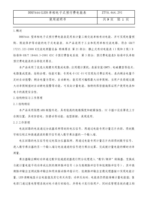
1.概述DDSY666型单相电子式预付费电能表是用来计量工频交流单相有功电能,并可实现电量预购、限流保护等功能的电子式电能表。
本产品适用于工业和民用单相交流电路。
符合GB/T 17215.321-2008《交流电测量设备 特殊要求 第21部分:静止式有功电能表(1级和2级)》标准和GB/T 18460.3-2001《IC卡预付费售电系统 第3部分:预付费电能表》标准中队单相预付费电能表的全部技术要求。
本产品采用了优选大规模专用集成电路,应用微计算机、表面安装(SMT)、电磁兼容等技术,电路集成度高,结构合理,性能可靠;专用电卡(IC卡)可实现先付费后用电、表内剩余电量不足时自动报警;剩余电量为零时,自动断电;能实现可编程最大功率限制,当用户负荷超过最大功率限制值时自动断电报警等功能,可双向计量电能,独特的保密措施保证用户使用电表和电卡的高度安全性。
2.结构特征与工作原理2.1结构特征本产品采用阻燃ABS树脂外壳,具有较高的绝缘强度和耐腐蚀性,IC卡插口设在罩壳上方右侧位置,具有防窃电、防潜动等功能,造型新颖,美观适用。
2.2工作原理电流回路的电流通过分流器采样得到的电压信号,再通过电能专用计量芯片内部,得到数字相位校正和高通滤波的数字信号进入数字乘法器的一个输入端。
电压回路的电压信号经过电阻分压器取样,再通过电能专用计量芯片内部得到数字信号,进入数字乘法器的另一个输入端与电流通道的信号进行乘法运算,完成被计量电能的瞬时功率测量。
乘法器输出瞬时功率通过数字低通滤波器进行积分处理进入“数字/频率”转换器,变换成与被计量电能平均功率成比例的频率脉冲信号(分为高频脉冲信号和低频脉冲信号),其中高频脉冲输出至测试脉冲输出和用来驱动脉冲指示灯,低频脉冲输出至微处理器接口实现电能计量。
LED清晰地显示出电能值及其它有关内容;功率反向时,电能表仍然能准确计量电能值;售电部门通过售电管理系统对电卡进行初始化,并将电卡发行给用户,同时在管理系统内建立档案,用户必须向售电部门购买电量后才能用电,用户的最大功率限制值由售电部门设定。
正泰电能表DDS666(485)单相电能表使用说明书

正泰电能表DDS666(485)单相电能表使用说明书
1.产品特点:
(1)采用3位半数码管,显示直观,具有放大系数和档系数自动换档;
(2)数字式滤波技术,具有抗干扰能力较强;
(3)计量准确,从0.1A到20A的量程均为一级精度;
(4)压力与负荷能力强。
2.技术参数:
(1)额定电压:220V或110V;
(2)额定电流:1.5(6)A、2.5(10)A、5(20)A、10(40)A、
15(60)A、20(80)A、30(100)A;
(3)频率:50Hz或60Hz;
(4)脉冲常数:6400imp/kWh或3200imp/kWh;
(5)温度范围:-25℃~+55℃。
3.使用方法:
可安装在户外式、配电柜式和铁箱式电能表中,使用时应注意保持电表的清洁、干燥和通风。
在接线过程中,应将电表的相序正确地安装,防止相序接反而导致测量不准确。
在使用电表时,还应避免高温、潮湿或冷却水直接喷射等特殊情况。
4.注意事项:
(1)使用电表前,要认真阅读《使用说明书》;
(2)使用过程中应顺手顺序牢记,避免出现接反等情况;
(3)请勿拆卸电表,以免影响电表的使用寿命和计量准确度;
(4)如需进行校验,请到相关的计量单位进行标准电表核验,以检验电表的准确性和是否符合计量标准的要求。
正泰三相智能电能表 DTSU666-20 快速安装指南说明书

Three-Phase Smart Energy MeterQuick Installation GuideDTSU666-20DTSU666-20-QIEN-Ver11-202208This manual is applicable to Sungrow Three-phase Smart Energy Meter.Keep the manual in a convenient place for future reference. The latest manual can be acquired at .DTSU666-20ApplicabilityOnly qualified personnel with the following skills are allowed to perform the work described in this document:Training in the installation and commissioning of the electrical systems.Familiar with the country/regional standards and specifications.Capable of coping with the dangerous and emergency situations during the installation and commissioning.Knowledge of and compliance with this manual and other related documents.Target GroupThe Smart Energy Meter is designed for indoor use only. It is a measuring device detecting the electrical values at the grid-connected point. It cannot be used for billing purposes. The data collected by the Smart Energy Meter on the PV power generation may differ from the data of the main Smart Energy Meter.Any use other than those described in this document does not qualify as appropriate usage and is prohibited. Do not make any modifications to the product.Damage or destruction may be caused to the Smart Energy Meter due to inappropriate usage. The Smart Energy Meter must not be operated beyond the values specified in the technical data.The following figure shows an application example of the Smart Energy Meter in the PV system. The inverterIntended Use* The RS485 cable is included in the accessories of the meter or the inverter.Related components in the scope of delivery: Smart Energy MeterRS485 cable *Quick installation guideDelivery ContentsTechnical Data320Vac ... 460Vac***/0.333V Nominal voltage Input voltage range 50Hz/60HzGrid frequency -25 ℃ ... +70 ℃Operating temperature < 75%(non-condensing )Relative humidity 118 x 72 x 65.5 mmDimensions (W x H x D)RS485 cableDTSU666-20Quick guideCurrent TransformerThree-phase Smart Energy Meter and its terminalsThree-phase Smart Energy Meter dimensions100 A CT dimensions250 A CT dimensionsDEFGLeft elevation* The current transformer (CT) is shipped separately or with the inverter.Step 3 Connect the plugs A and B to terminals A and B on the Smart Energy Meter.Mount the Smart Energy Meter to a 35 mm DIN rail. Hook it into the top edge of the rail and press down until it snaps into place.InstallationCable ConnectionThe line conductor L1 supplies power to the Smart Energy Meter. The line conductor L1 and neutral conductor must be connected to the terminal 2 and terminal 10 of the Smart Energy Meter respectively.If there is only L1(to terminal 2), or L2 (to terminal 5), or L3 (to terminal 8), and the neutral conductor (to terminal 10), then the three-phase Smart Energy Meter can be used as a single-phase Smart Energy Meter.Step 1 Turn off solar switch, load switch, main switch and other power switches, and secure them against reconnection.Step 2 Take out the RS485 cable from inverter’s packaging or Smart Energy Meter’s packaging .Output terminals to the load sideA 2, 5, 8, 10D C A, BB LCD display Key Displays active energy and reactive energy, etc SET: confirm the selection or settingsESC: return to a previous menu or cancel the settings →: increase the setting value Communication terminals E 1, 3, 4, 6, 7, 9CT1 Current Input F 31, 33, 34, 36, 37, 39CT2 Current InputG91Power supply of Rogowski coil (5V)Step 4 Strip the insulation from the power wires by 10 mm. Then connect wires to the terminals on the Smart Energy Meter, as shown below. ( Cross-section: 1mm to 6mm )Retrofit (Three-phase hybrid inverter + Three-phase PV inverter + Three-phase grid)Retrofit (Three-phase hybrid inverter + Single-phase PV inverter + Three-phase grid)Retrofit (Single-phase hybrid inverter + Single-phase PV inverter + Single-phase grid)Step 5 For inverter cable connection, refer to the user manual of the corresponding inverter.Step 6 Cover the Smart Energy Meter with the insulating cover or contact protection of the sub-distribution. Switch on the power supply to the sub-distribution.The CT direction must be consistent with the arrow direction as shown in the preceding figure.The maximum torque of 2, 5, 8 and 10 terminal screws is 1.7N.m, and the recommended torque is (1.0 ± 0.1) N.m; The maximum torque of 13, 14, 16, 17, 19, 21, 24 and 25 terminal screws is 0.4N.m, and the recommended torque is (0.20 ± 0.05) N.m.NOTICEFor details about the installation direction and cable connection of the current transformer, please refer to the information on the side of the current transformer.Note:Connect CT1 to terminal 1 and terminal 3 of the smart energy meter, and CT2 to terminal 31 and terminal 33.From the displayed interface, the electrical parameter and energy data are all primary side data (that is, the multiplied by current and voltage ratios). The energy measuring value will be displayed seven bits, with the displaying range from 0.00kWh to 9999999MWh.Displayed function8First channelPhase A voltage =5.002ACombined phase active power 23When RS485 communicating, the telephone sign will flashes.The communication address of Modbus protocol is 1 decimal data (1 ~ 254), and the factory default baud rate is 9600bps, N.8.1; E1 means even check one stop bit, O1 means odd check one stop bit, N2 means two stop bits without check, N1 means one stop bits without check.PFb=0.500PFc=-0.500The meter parameters have been set before delivery. It can be installed directly after acception and there is no need to set parameters again. Button description: “SET” represents “confirm” or “cursor shift” (when input digits), “ESC” represents “exit”, and “→” represents “add”. The password is 701 by default.Programming functionProgramming ParameterProgramming ParameterParameterValue range DescriptionVoltage ratio, used for setting the voltage ratio of the input loop.When the voltage is connected to the line via the transformer, Pt= the rated voltage of the primary loop / the rated voltage of the secondary circuit.When the voltage is directly connected to the line, Pt shall be set as 1.0.1: 6452: n.23: n.14: E.15: O.1Settings for communication stop bit and Parity: bits1: 645mode2: None parity, 2 stop bits, n.23: None parity, 1 stop bit, n.14: Even parity, 1 stop bit, E.15: Odd parity, 1 stop bit, O.10: 1.2001: 2.400 2: 4.8003: 9.600Communication baud rate: 0: 1.200 bps 1: 2.400 bps 2: 4.800 bps 3: 9.600 bps1 ~ 254 Communication address 0: n.34 1: n.33Option for wiring mode:0: n.34 represents three phase four wire 1: n.33 represents three phase three wire0: P01: P1Pulse output:0 ~ 30Display in turns(second) 0: Timely display1 ~ 30: Time interval of actual display 0 ~ 30Backlight lighting time control(minute)0: Normally light 1 ~ 30: Backlight lighting time without button operation1 ~ 880.1 ~ 1.01:CT01:100A/333mV 2:CT02:250A/333mV 3:CT03:400A/333mV 4:CT04:500A/333mV 5:RS01:1000A/333mV 6:RS02:2000A/333mV 7:RS03:3000A/333mV 8:RS04:4000A/333mVP0: First channel actsive energy pulseP1: Second channel actsive energy pulseWhen input digits, “ ” can be used as cursor “ - ”motion button, “ ”is “add” button, “ ”is Exit the programming operation interface or switch to the character interface from digit modification interface, add from the beginning after setting the digit to the maximum value.Troubleshooting1. If the wiring mode is incorrect, please connect based on the correct wiringmode.2. If the supplied voltage is abnormal, pleasesupply the voltage on the instrument specification.1. If any problems for the communication cable, please change the cable.2. Set the address, baud rate, data bit and parity bit of the instrument to be the same as the inverter through buttons and so as the "parameter setting".1. For wrong wiring, please connect based on the correct wiring mode.2. If a negative value is displayed, change the cable connection mode of the current transformer to ensure that the high and low ends are connected properly.No display after theinstrument being powered onAbnormal RS485 communicationPower metering inaccuracy1. Incorrect wiring mode.2. Abnormal voltage supplied for theinstrument.1. The RS485 communication cable is disconnected, short circuit or reversely connected.2. The address, baud rate, data bit and parity bit of the instrument is not in accordance with the inverter.whether the corresponding phase sequence of voltage and current is correct.2. Check whether the high and low ends of the current transformer inlet are reversely connected. Pa, Pb , and Pc are abnormal if the values are negative.21。
浙江正泰仪器仪表有限责任公司DDSU666系列单相电子式电能表(导轨)使用说明书

DDSU666系列单相电子式电能表(导轨)使用说明书ZTY0.464.922浙制00000205号浙江正泰仪器仪表有限责任公司二0一六年八月目录1.概述 (1)2.工作原理 (2)3.主要技术性能与参数 (3)4关键零部件采用 (4)5.主要功能 (5)6.外形及安装尺寸 (11)7.安装及使用说明 (12)8.常见故障的诊断、分析、排除方法 (13)9.运输与贮存 (14)10.保修与服务 (14)DDSU666系列单相电子式电能表(导轨)ZTY0.464.922使用说明书共15页第1页1.概述1.1主要用途及适用范围DDSU666系列单相电子式电能表(导轨)(以下简称“仪表”)根据电力系统、通信行业、建筑行业等电力监控和电能计量需求而设计,为新一代智能仪表,集测量、通讯于一体,主要用于电气线路中电压、电流、功率、频率、功率因数、有功电能等电参量的测量与显示。
可通过RS485通讯接口与外部装置实现组网;采用标准DIN35mm导轨式安装,结构模数化设计,具有体积小、易安装、易组网等优点;广泛应用于工矿企业、宾馆、学校、大型公建内部电能考核与监测。
符合的标准:GB/T17215.321-2008《交流电测量设备特殊要求第21部分:静止式有功电能表(1级和2级)》DL/T645-2007《多功能电能表通信协议》1.2产品特点1)计量正反向有功电能,反向电能按正向累计;2)采用温宽型LCD;3)DIN35mm标准导轨式安装,结构模数化设计,体积小、易安装、易组网。
资料来源编制<**设计签字**><**设计签字日期**>校对<**校对签字**><**校对签字日期**>审核<**审核签字**><**审核签字日期**>标准化<**标准化签字**><**标准化签字日期**>提出部门审定<**审定签字**><**审定签字日期**>标记处数更改文件号签字日期职责签字日期1.3型号组成及代表意义图1型号组成1.4使用环境条件规定的工作温度范围:-25℃~+55℃;极限的工作温度范围:-40℃~+70℃;相对湿度(年平均):≤75%;大气压:86kPa~106kPa。
正泰昆仑DDSY666 型单相电子式预付费电能表 数据表

LED显示 LCD显示
1 产品概述
DDSY666型单相电子式预付费电能表主要适用于实行先付费后用电供电制度的单相居民用户,可 实现电能计量、电量预购、最大负荷限制等功能。该产品是用电收费改革,提高供用电科学管理水 平,促进合理用电,节约用电的理想电能计量产品。
2 主要功能及特点
● 准确计量正、反向有功电能,反向电能按正向累计 ● 可预售电量,当电量用完后自动断电,断电阀值可设 ● 一表一卡多重动态加密,用户数据安全可靠 ● 具有信息传递功能,通过用户卡可将电能表中的计量数据和工作状态数据返回到售电系统,供
结算、统计、管理使用 ● 具有错误操作和故障提示功能 ● 显示方式可选:LED显示和LCD显示 ● 具有红外和RS485通信接口(仅LCD显示电能表)
4 符合标准
GB/T 17215.321-2008、GB/T 17215.211-2006、 GB/T 18460.3-2001、DL/T 645-2007
5 外形及安装尺寸
60
1.5
125
142
10
88
3 主要技术参数
项目 准确度等级 电压规格 电流规格 参比频率 电压范围
工作温度范围
功耗 显示方式
技术指标 有功1级、2级 220V 5(40)A、5(60)A、10(80)A 50Hz 规定的工作电压范围:0.9Un~1.1Un 扩展的工作电压范围:0.7Un~1.2Un 规定工作温度范围:-25℃~60℃ 极限工作温度范围:-40℃~70℃ 电压线路:≤1W/5VA 电流线路:≤1VA LED显示、LCD显示
- 1、下载文档前请自行甄别文档内容的完整性,平台不提供额外的编辑、内容补充、找答案等附加服务。
- 2、"仅部分预览"的文档,不可在线预览部分如存在完整性等问题,可反馈申请退款(可完整预览的文档不适用该条件!)。
- 3、如文档侵犯您的权益,请联系客服反馈,我们会尽快为您处理(人工客服工作时间:9:00-18:30)。
1.概述DDSY666型单相电子式预付费电能表是用来计量工频交流单相有功电能,并可实现电量预购、限流保护等功能的电子式电能表。
本产品适用于工业和民用单相交流电路。
符合GB/T 17215.321-2008《交流电测量设备 特殊要求 第21部分:静止式有功电能表(1级和2级)》标准和GB/T 18460.3-2001《IC卡预付费售电系统 第3部分:预付费电能表》标准中队单相预付费电能表的全部技术要求。
本产品采用了优选大规模专用集成电路,应用微计算机、表面安装(SMT)、电磁兼容等技术,电路集成度高,结构合理,性能可靠;专用电卡(IC卡)可实现先付费后用电、表内剩余电量不足时自动报警;剩余电量为零时,自动断电;能实现可编程最大功率限制,当用户负荷超过最大功率限制值时自动断电报警等功能,可双向计量电能,独特的保密措施保证用户使用电表和电卡的高度安全性。
2.结构特征与工作原理2.1结构特征本产品采用阻燃ABS树脂外壳,具有较高的绝缘强度和耐腐蚀性,IC卡插口设在罩壳上方右侧位置,具有防窃电、防潜动等功能,造型新颖,美观适用。
2.2工作原理电流回路的电流通过分流器采样得到的电压信号,再通过电能专用计量芯片内部,得到数字相位校正和高通滤波的数字信号进入数字乘法器的一个输入端。
电压回路的电压信号经过电阻分压器取样,再通过电能专用计量芯片内部得到数字信号,进入数字乘法器的另一个输入端与电流通道的信号进行乘法运算,完成被计量电能的瞬时功率测量。
乘法器输出瞬时功率通过数字低通滤波器进行积分处理进入“数字/频率”转换器,变换成与被计量电能平均功率成比例的频率脉冲信号(分为高频脉冲信号和低频脉冲信号),其中高频脉冲输出至测试脉冲输出和用来驱动脉冲指示灯,低频脉冲输出至微处理器接口实现电能计量。
LED清晰地显示出电能值及其它有关内容;功率反向时,电能表仍然能准确计量电能值;售电部门通过售电管理系统对电卡进行初始化,并将电卡发行给用户,同时在管理系统内建立档案,用户必须向售电部门购买电量后才能用电,用户的最大功率限制值由售电部门设定。
图1原理框图2.3产品型号组成以及代表意义:设计序列号预付费电子式单相电能表3.主要技术性能与参数·准确度等级:1级;2级;·参比频率:50Hz;·参比电压:220V;·规定的工作电压范围: 90%~110%Un;·扩展的工作电压范围: 80%~115%Un;·电流规格:2.5(10)A、5(20)A、5(30)A、10(40)A、15(60)A、20(80)A;(可按用户要求定做)·工作温度范围:-25℃~55℃·极限工作温度范围:-40℃~70℃·仪表常数:800imp/kWh-6400imp/kWh(以铭牌标注为准)·电压线路功耗:≤1.5W/(5VA);·起动电流:在参比电压,参比频率及COSФ=1的条件下,负载电流为0.004Ib(1级)、0.005Ib(2级)时,电能表能起动并连续计量电能。
·潜动:在电流回路断开,电压回路施加参比电压的115%,电能表的测试输出端不产生多于一个的脉冲。
·百分数误差极限各等级电能表百分数误差极限 电流值 功率因素1 20.05Ib≤I<0.1Ib 1.0 ±1.5 ±2.50.1Ib≤I≤Imax 1.0 ±1.0 ±2.00.1Ib≤I<0.2Ib 0.5 (感性)0.8(容性)±1.5±1.5±2.5-0.2Ib≤I≤Imax 0.5(感性)0.8(容性)±1.0±1.0±2.0-注:Ιb-为基本电流值·功能与特点本产品除具有普通电能表测量消耗电能的功能外,还具以下功能与特点:1)预付费功能:通过对电能表和IC卡进行微机管理,实现预付费用电管理功能,用户必须持卡到供电部门购电,将电量输入电能表后方能正常用电。
2) 显示功能:六位组合数码管,轮换显示,累计用电量:0~99999.9kWh、当前可用剩余电量:0~9999kWh、最近一次购电量:0~9999kWh、等三项内容。
3) 报警功能:剩余电量少于一级报警电量时报警灯闪烁,剩余电量少于二级报警电量时断电报警,提醒用户赶快买电,此时用购电卡(有无电量均可)插入表中,可恢复供电,直到剩余电量全部用完后断电,此时须买电后才能恢供电。
4) 超负荷断电:当负载功率超过设定值时(此值由电力管理部门设定,并通知用户)断电5min报警,提醒用户降低负荷,5min后恢复供电.若仍然超负荷,则继续断电报警。
5) 信息传递功能:能将电能表当前状态、用电信息反写至售电卡中,购电时再由卡写入到售电管理部门的售电系统中,方便对用户电能表运行状态的检查。
6) 叠加功能:输入电能表的本次购电量能与电能表内的剩余电量自动相加。
7) 透支功能:电表在购电时,能自动扣除上次透支电量。
8) 可双向计量电能,具有防窃电功能。
9) 采用磁保持继电器,使用可靠,寿命长。
10) 卡座加装抗攻击模块,抗攻击范围:DC2500V,AC600V,静电30kV。
4.外形及安装尺寸≤10(40)A电流规格外形及安装尺寸图2 ≤10(40)A电流规格安装尺寸图≥15(60)A电流规格外形及安装尺寸图3 ≥15(60)A电流规格外形图说明5.运输与贮存电能表的运输和贮存不应受到剧烈的冲击,并根据JB/T9329-1999《仪器仪表运输、运输贮存基本环境条件及试验方法》的规定运输和贮存。
在搬运、取用、安装过程中受到剧烈撞击或高空跌落造成外壳有明显损毁痕迹时,请不要对该表加电,并尽快联络供应商;如果短时间内不安装使用,请将表包装好放回原包装箱收藏;保存、安装地点周围尽量避免有化学物品泄露或高电磁辐射干扰;保存电能表应在原包装内,保存的环境温度为0℃~40℃,相对湿度不超过85%,空气中应无腐蚀性气体。
原包装箱中缺少物品清单中所列对象或不符时,请与供应商联络;电能表应存放在仓库里,叠放的高度不应超过5层,拆箱后单只包装的电能表叠放高度不超过10只。
6.安装与使用说明 6.1电能表安装电能表在出厂之前经检验合格,并加铅封;电能表的安装应按接线图连线,接线图如图图4 ≤10(40)A电流规格端子接线图NL 图5 ≥15(60)A电流规格端子接线图※注意事项1)≤10(40)A电流规格端子2,5端和≥15(60)A电流规格端子9,10端为脉冲测试输出端,切勿接入220V电压.2)本表因有断电功能,不能直接接入电流互感器二次侧,否则将造成事故,应直接接入单相供电回路中, 接线图参照图4和图5。
3)建议使用一个十字槽沉头自攻螺钉和两个开槽圆头木螺钉4×35进行安装固定。
4)电能表应安装在室内使用,安装表的底板固定在坚固耐火的墙上,建议安装高度为1.8米左右,空气中无腐蚀性气体。
6.2使用、操作6.2.1各IC卡的分类和功能如下:·初始化卡:用于将初次安装的电能表设置为运行状态,并且完成一表一卡的对应工作,而此卡在完成对电能表设置后将转化为售电卡。
·售电卡:用户持有,用于向运行状态的电能表中增加购电量,并将电能表中的数据返写回售电管理部门。
·补卡:结构同售电卡,用于为丢失售电卡的用户补发售电卡。
·检测卡:用于检测电能表中的各种数据信息是否正确。
在电能表处于任何逻辑状态下均可使用,为售电管理部门和制造厂通用。
·空卡:用于在售电系统中生成以上各种卡,该卡本身不含任何信息.6.2.2 用户需持所配售电卡到供电部门指定的售电点购电,购买的电量将由售电系统写入卡中;购电后,用户将售电卡的正面(该面带金属接触片)朝电表的内侧插入电能表的电卡插口内,电能表显示器会先显示Cd,再显示累计剩余可用电量,即表示购买的电量已输入电能表中。
然后可将售电卡拔出,妥善保存。
6.2.3电能脉冲输出指示灯:脉冲指示灯每点亮一次,脉冲输出接口产生一个脉冲,同时内存中将进行电能累计。
6.2.4本表平时轮换显示以下三项内容:A:已用电量,B:当前剩余电量,C:最近一次购电量。
显示器示意图如图7所示:图7 显示器说明1)指示灯(A)点亮时,指示当前显示内容(五位整数和一位小数)为累计用电量的万、千、百、十、个位和一位小数,该内容自表通电使用之时开始累计,当用电量超出99999.9kW·h,显示器清零后仍然显示累计用电量的万、千、百、十、个位和一位小数(不显示十万位及以上位),而累计用电量在电能表内最大可一直计量到999999.9kW·h。
2)指示灯(B)点亮时,指示当前显示内容(六位整数)为可用剩余电量,最大为9999kW·h。
3)指示灯(C)点亮时,指示当前显示内容(六位整数)为最近一次购电量,最大允许9999kW·h。
以上三项内容循环显示.4)报警指示灯闪烁点亮时,指示当前剩余电量小于一级报警电量。
6.2.5累计用电量和可用剩余电量通过电卡在每次购电时传递给售电系统进档和统计,而卡中的购电量则在每次输入到电能表后被取消;当表内剩余电量小于一级报警电量时显示器右下角的报警指示灯会一直闪烁报警,提示用户尽快购电;若小于二级报警电量(该电量小于一级)时除报警指示灯闪烁报警外,还会断电报警,再次提示用户尽快购电,此时插入售电卡,显示器显示Cd后,恢复供电,可拔出电卡,直至表内剩余电量用完;当表内剩余电量为零时,会自动切断供电回路; 用户必须购电后,才能恢复供电(按步骤6.2.2操作),报警指示灯停止闪烁报警。
此外插卡提示和出错信息显示有:a、初始化卡正确插入表上时显示:Cd;b、售电卡正确插入表上,先显示:Cd,后显示累计剩余可用电量;c、检测卡正确插入表上时显示:Cd;d、非法卡插入电能表时,显示:CC;e、空卡插入电能表显示:00;f、存储器故障显示:EE;g、售电卡或补卡插入表上,表内剩余电量和卡内购电量之和大于9999kW·h(度)时,会显示:dd;6.2.6若用户用电负荷超过限定值(即允许最大电流值)时,本电表自动断电,五分钟后自动合闸,若用电负荷仍然超过,则继续断电,从而使用户在限定的负荷范围内用电,保证了安全用电;该限定值若需增容或调整,需到售电部门修改,将售电卡交给售电员插在读写卡器上,按下售电系统的IC卡操作按钮,在弹出的窗口中选择售电卡选项,读卡成功后修改其限定值,修改后将售电卡插在电能表上,显示器显示Cd, 表示已成功将修改内容写进电能表内,可将卡拔出。
6.2.7 若售电卡丢失,请及时到售电部门补配。