ZEBRA斑马技术kr203 英文数据表
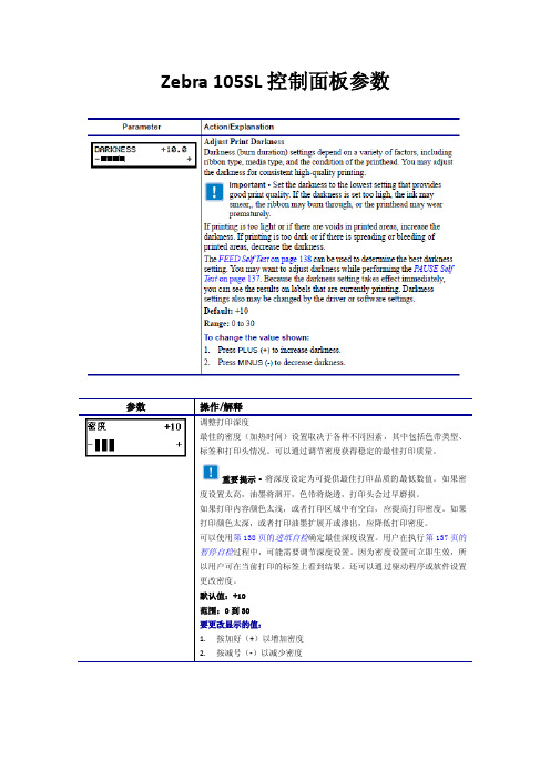
Zebra 105SL控制面板参数中英文对照
·按减号 (-) 可选择 NO (否)取消请求,并返回到 FORMAT CARD (格 式化存储)提示符。 ·按加号 (+) 键,选择 YES (是),还是执行初始化。 初始化完成后,打印机将自动退出设置模式,并在 控制面板显示打 印 机就绪 。如果你在初始化过程中退出设置模式,控制面板显示屏上会 闪烁显示 CHECKING B:MEMORY(检查 B 磁盘:内存)和 PRINTER IDLE (打印机空闲 )两个选项。
注意:代码页 850 需要被设置为 8 位数据位。有关详细信息, 请参见 ZPLⅡ编程指南。 默认值:8 位 选项:7 位、 8 位 要更改显示的值: 1. 按加号 (+) 或减号 (-) 可在选项之间切换。
显示屏显示 INITIALIZE FLASH? (是否要格式化闪存?) 3. 按加号(+)选择 YES(是)。
显示屏将显示 ARE YOU SURE? (您是否确定?) 4. 是否要继续?
·按减号 (-) 可选择 NO (否)取消请求,并返回到 INITIALIZE FLASH (初始化闪存)提示符。 ·按加号 (+) 键,选择 YES (是),还是执行初始化。 初始化完成后,打印机将自动退出设置模式,并在 控制面板显示打 印 机就绪 。如果你在初始化过程中退出设置模式,控制面板显示屏上会 闪烁显示 CHECKING E:MEMORY(检查 E 磁盘:内存)和 PRINTER IDLE (打印机空闲 )两个选用于告知打印机您使用的参数类型(有关详细信息,请参见第 33 页 的介质类型)。如果选择了连续介质,必须在标签格式中包括一个标签长度 指令(如果使用 ZPL 或 ZPL Ⅱ,应为^LLxxxx)。 如果选择非连续介质,打印机将介质送入以计算标签长度(在标签内隔隙、 网纹、对齐缺口或切孔上识别到的两个对准点之间的距离)。 默认值: 间隙/凹口 选项: 间隙/凹口、标记、连续 要更改显示的值: 1. 按加号(+)或减号(-)可在选项之间滚动。 设置传感器类型
Zebra 105SL打印机驱动设置翻译

Zebra 105SL打印机驱动中英文对照表Paper/Output 纸/输出Paper Layout 纸布局: portrait 纵向、Landscape 横向Paper Size 纸张尺寸:Copies 复印份数:1Rotate 180 旋转180:OFFmirror 反光镜:OFFNegative 负向:OFFTop Adjustment 顶部调节:0Media Settings 介质设置Media Type 打印类型:Direct 热敏、Thermal Transfer 热转印Media Tracking 标签类型:Continuous 连续纸、Non Continuous 非连续纸、Non Continuous Mark Sensing 非连续标志检测、Use printer setting 使用打印机设置Document Options 文件选项Dispense Mode 剥离模式:Rewind Printed Labels 回卷、PEEL OFF 剥离、T ear off 撕裂、Cut Label 切刀、Use printer setting 使用打印机设置Smart Download 智能下载:OFFConfiguration 配置:Use Driver setting 使用驱动设置、Use printer setting 使用打印机设置Device Options 设备选项Speed Settings 速度设置Print Speed 打印速度Slew Speed 回转速度Back Feed Speed 标签回撤速度Head Settings 打印头设置Print Darkness 打印深度Printer Actos 打印机的行为on Power UP 在开关电源时:Do Nothing 不动、Do Calibration 效验纸张、Set Label Length 设置标签长度、Feed Label 走纸、Use printer setting 使用打印机设置on Head Close 打印头翻开合上时:(同上)User Commands 用户命令任务Start of Job 开始的工作:Do Nothing 什么都不做、Enter Commands 输入命令End of Job 结束的工作:(同上)Start of Page 开始的页面:(同上)End of Page 结束的页面:(同上)Printer Firmware 打印机固件Firmware 固件。
Zebra斑马ZT230条码打印机规格介绍

128、UPC-
A、UPC-
E、EAN-
8、EAN-
5、Industrial 2-of-
5、Interleaved 2-of-
二维条码:
Aztec、Codablock、P
DF417、Code
49、DataMatrix、MaxiCode、QRCode、MicroP
每秒152毫米/6英寸
介质传感器
传输式和反射式
介质特征
最大标签和衬纸宽度:114毫米/
4.5英寸
非连续标签最大长度:991毫米/39英寸
介质宽度
19.4毫米/
0.75英寸至
11.4毫米/
4.50英寸
打印长度
203dpi:3988毫米/157英寸
300dpi:1854毫米/73英寸
最大介质卷尺寸
外径203毫米/
8.0英寸,卷芯内径76毫米/
3.0英寸
卷芯外径152毫米/
6.0英寸,卷芯内径25毫米/
1.0英寸
介质厚度
0.076毫米/
0.003英寸至
0.25毫米/
0.010英寸
介质类型
连续纸、模切纸、标签纸、黑标纸
碳带规格
(仅限热转印选项)
外径
81.3毫米/
3.2英寸
卷芯内径
25毫米/
1.0英寸(ZT230)
DF417、TLC
39、RSS-14(和附加码)
字体和图形
七种点阵字体,一种平滑向量字体(CG TriumvirateTM粗体压缩字)包括Agfa MonotypeCorporation的UFST®
赛米控丹佛斯电子 SK80MB120CR03TE1 数据表
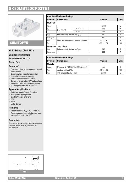
© by SEMIKRONRev. 0.9–24.09.20211®E1Half-Bridge (Full SiC)Engineering Sample SK80MB120CR03TE1Target Data Features*•Optimized design for superior thermal performance•Extremely low inductance design •Press-Fit contact technology •1200V Planar Gen3 SiC MOS•Simple to drive with +15V gate voltage •Integrated NTC temperature sensor •UL recognized file no. E 63 532Typical Applications•Switched Mode Power Supplies •Energy Storage Systems •Electric Vehicle charging •UPS •Solar •Motor DrivesRemarks•Recommended T j,op =-40 ...+150 °C •Recommended turn-off / turn-on gate voltage V GS = -4...0/+15VFootnotes1) SEMIKRON Exclusive High PerformanceThermal Paste (HPTP), available as pre-appliedAbsolute Maximum Ratings SymbolConditions Values UnitMOSFET 1V DSS 1200V I D T j =175°CT s =25°C 98A T s =70°C82A I DMPulse width t p limited by T jmax240A I DM,repetitive120A V GS Max. transient gate - source voltage-8...19V T j-55 (175)°C Integrated body diode I FMPulse width t p limited by T jmax240A I FM,repetitive120AAbsolute Maximum Ratings SymbolConditions Values UnitModule I t(RMS)∆T terminal at PCB joint = 30 K, per pin 30A T stg module without TIM -40...125°C V isolAC, sinusoidal, t =1min2500V2Rev. 0.9–24.09.2021© by SEMIKRON®E1Half-Bridge (Full SiC)Engineering Sample SK80MB120CR03TE1Target Data Features*•Optimized design for superior thermal performance•Extremely low inductance design •Press-Fit contact technology •1200V Planar Gen3 SiC MOS•Simple to drive with +15V gate voltage •Integrated NTC temperature sensor •UL recognized file no. E 63 532Typical Applications•Switched Mode Power Supplies •Energy Storage Systems •Electric Vehicle charging •UPS •Solar •Motor DrivesRemarks•Recommended T j,op =-40 ...+150 °C •Recommended turn-off / turn-on gate voltage V GS = -4...0/+15VFootnotes1) SEMIKRON Exclusive High PerformanceThermal Paste (HPTP), available as pre-appliedCharacteristics SymbolConditions min.typ.max.UnitMOSFET 1V (BR)DSS V GS =0V,I D =0.1mA, T j =25°C 1200V V GS(th)V DS =V GS , I D =23mA,T j =25°C 1.82.53.6V I DSS V GS =0V,V DS =1200V, T j =25°C 1mA I GSS V DS =0V,V GS =15V,T j =25°C 200nA R DS(on)V GS =15V I D =83AchiplevelT j =25°C 1622m ΩT j =150°C 25m ΩC iss V GS =0V,V DS =1000V, f =0.1MHz 6800pF C oss V GS =0V,V DS =1000V, f =0.1MHz 260pF C rss V GS =0V,V DS =1000V, f =0.1MHz 20pF R Gint T j =25°C5.9ΩQ G V DD = 800 V, V GS = -4 V ... 15 V, I D =83A 236nC t d(on)V DD =600V V GS =15/-4V I D =80AR Gon =1ΩR Goff =1Ωdi/dt off =5.6kA/µs di/dt on =7.1kA/µsdv/dt =28kV/µsT j =150°C 36ns t d(off)T j =150°C 90ns t r T j =150°C16ns t f T j =150°C 23ns E on T j =150°C 1.02mJ E off T j =150°C0.69mJ R th(j-s)per MOSFET, λpaste =2.5 W/(mK) 1)0.51K/W Integrated body diodeV F = V SD -I D =41AV GS =-4V chiplevelT j =25°C 4.58V T j =150°C 4.30V V F0 = V SD0chiplevel T j =25°C 3.80V T j =150°C 3.60V r F = r SD chiplevelT j =25°C 19m ΩT j =150°C 17m Ωt rr V DD =600V -I D =80A V GS =-4V R Gon =1Ωdi/dt off =7.3kA/µsT j =150°C 33ns Q rr T j =150°C 1.4µC I rr T j =150°C 86A E rrT j =150°C0.81mJCharacteristics SymbolConditions min.typ.max.UnitModule L CE 9nH M s to heatsink 1.62.3Nm wweight25gCharacteristics SymbolConditionsmin.typ.max.UnitTemperature SensorR 100T r =100°C493 ± 5%ΩB 100/125R (T)=R 100exp[B 100/125(1/T-1/T 100)]; T[K];3550 ±2%K© by SEMIKRON Rev. 0.9–24.09.202134Rev. 0.9–24.09.2021© by SEMIKRON© by SEMIKRON Rev. 0.9–24.09.202156Rev. 0.9–24.09.2021© by SEMIKRONThis is an electrostatic discharge sensitive device (ESDS) due to international standard IEC 61340.*IMPORTANT INFORMATION AND WARNINGSThe specifications of SEMIKRON products may not be considered as guarantee or assurance of product characteristics ("Beschaffenheitsgarantie"). The specifications of SEMIKRON products describe only the usual characteristics of products to be expected in typical applications, which may still vary depending on the specific application. Therefore, products must be tested for the respective application in advance. Application adjustments may be necessary. The user of SEMIKRON products is responsible for the safety of their applications embedding SEMIKRON products and must take adequate safety measures to prevent the applications from causing a physical injury, fire or other problem if any of SEMIKRON products become faulty. The user is responsible to make sure that the application design is compliant with all applicable laws, regulations, norms and standards. Except as otherwise explicitly approved by SEMIKRON in a written document signed by authorized representatives of SEMIKRON, SEMIKRON products may not be used in any applications where a failure of the product or any consequences of the use thereof can reasonably be expected to result in personal injury. No representation or warranty is given and no liability is assumed with respect to the accuracy, completeness and/or use of any information herein, including without limitation, warranties of non-infringement of intellectual property rights of any third party. SEMIKRON does not assume any liability arising out of the applications or use of any product; neither does it convey any license under its patent rights, copyrights, trade secrets or other intellectual property rights, nor the rights of others. SEMIKRON makes no representation or warranty of non-infringement or alleged non-infringement of intellectual property rights of any third party which may arise from applications. Due to technical requirements our products may contain dangerous substances. For information on the types in question please contact the nearest SEMIKRON sales office. This document supersedes and replaces all information previously supplied and may be superseded by updates. SEMIKRON reserves the right to make changes.In accordance with the quality guidelines of SEMIKRON, we would like to point out that the products are engineering samples. These engineering samples are not yet produced under quality conditions approaching those of series production, and are at the present time not included in the SEMIKRON quality monitoring and control process. Neither the product nor the production process has to date gone completely through the SEMIKRON internal authorization procedure. SEMIKRON may make any amendments without any prior notification. SEMIKRON cannot and shall not promise or commit itself to release and/or make available a final version or series product after the development phase. SEMIKRON cannot and will not assume any responsibility with regard to freedom from defects, functionality, and adaptation to and interaction with possible applications of the user or with regard to any other potential risks resulting from the use of engineering samples. Therefore SEMIKRON explicitly excludes any warranty and liability; as far as legally possible. The customer shall fully indemnify and hold harmless SEMIKRON from any and all risks, damages, losses, expenses and costs directly or indirectly resulting out of or in connection with the commissioning, operation, system integration, sale, dissemination or any other kind of use of engineering samples by the customer and/or any third party, which has come into possession of engineering samples through or because of the customer. All know-how and all registerable and non-registerable copyrights and industrial property rights arising from or in connection with these engineering samples remain the exclusive property of SEMIKRON.7。
MARL 203 SERIES PACK QUANTITY = 20 PIECES 说明书

Y es Y es Y es Direct replacement for T1¼ Bi-PinFlat-topped for enhanced, even illumination of large lens areasImproves equipment reliability‘Fit &Forget’reliabilityWarm White LEDs may be used behind coloured lens as a true replacement for a filament lampFILAMENT REPLACEMENT LEDs - T1¼Ordering Information & Typical T echnical Characteristics (T a = 25°C)Mean Time Between Failure = 100,000 Hours. Luminous intensity figures refer to the unmodified discrete LED.SPECIFICA TIONS203 SERIESP ACK QUANTITY = 20 PIECESHow to Order:website: •email:*************.uk ••T elephone +44 (0)1229 582430•Fax: +44 (0)1229 585155Please note that this product is also available in different voltages. Contact our sales department for further details.^ = Products must be derated according to the derating information. Each derating graph refers to specific LEDs. Appropriate LED numbers shown. - Refer to page 3.998*Typical emission colour cool white x 0.2960.2830.3300.330y0.2760.3050.3390.318991**Typical emission colour warm white x 0.36100.35410.45880.5080y0.39000.34010.38380.4720Intensities (lv) and colour shades of white (x,y co-ordinates) may vary between LEDs within a batch.203 SeriesHow to Order:website: •email:*************.uk ••T elephone +44 (0)1229 582430•Fax: +44 (0)1229 585155Dimensions in mm (Typical)Not to scaleResistor lead signifies positive termination +ve.Colour dot on product denotes LED colourSingle-Chip LEDsAll devices feature water clear high intensity LEDs as standard. The single chip LED devices have been modified by the removal of the domed portion of the encapsulation (flat-topped) to provide even illumination of switches and annunciators. Non flat topped versions are also available,please contact the sales department for details.Product EvaluationFilament Replacement LEDs have been specifically designed to meet the primary objective of providing improved reliability . As this product range is suitable for both new-build and retro-fit, (sometimes in very old systems), a wide range of illuminated push button switches and lamp holders can be encountered. Due to subjectivity , evaluation of the LED type is recommended, (samples of all standard models are available). Care should be taken to correctly simulate operating ambient light conditions to ensure that the correct device has been selected to maximise viewing characteristics such as viewing angle, colour compatibility and on/off contrast ratio.Electro-static Discharge (ESD)Build up of electro-static discharge occurs in many situations involving people moving and handling products. The range of possible situations is very diverse but voltage levels as high as several thousand volts can and do arise in many individual situations. When an operator charged up to these levels handles a ‘static sensitive device’, there is a very probable likelihood that the device will be irreversibly damaged. It is essential that precautions are taken at all stages during manufacture and assembly of these products. Although LEDs were never considered to be static sensitive devices, changes in manufacturing technology and materials used to produce higher intensity products over a large range of thewavelength spectrum have changed this. Marl has an approved system of ESD control from goods in, through production and into final packing and despatch. We recommend all users of LED based products follow the guidelines of BS 100015.Power de-ratingThe forward voltage/current value of an LED is dependant upon the ambient temperature of the environment in which it is operated. Therefore,care must be taken to operate the LED at the correct voltage/current values, depending upon the ambient temperature. Consequently , a recommendation regarding operating voltages and currents is given in order to address these temperature effects. This recommendation is termed ‘de-rating’.It is usual for forward voltages and currents to be specified for ambient temperature of 25°C. However, because the values of these qualities vary with temperature, Marl should be contacted if the device is to be operated at a temperature significantly higher than 25°C.Marl accept no liability for any product that is operated higher than the stated voltage.Note: All luminous intensity figures refer to the unmodified discrete LED.How to Order:website: •email:*************.uk ••T elephone +44 (0)1229 582430•Fax: +44 (0)1229 585155301991325324, 934 & 998。
斑马ZebraZPLII指令集中文说明解释

斑马ZebraZPLII指令集中⽂说明解释我们最常⽤的斑马(Zebra)条码打印机,应⽤ZPLII命令来控制打印,说明书中有每条指令的详细说明及相关⽰例,下⾯是各指令的中⽂释义:^A 对Zebra内置点阵字体缩放 ^A(可缩放/点阵字体)命令⽤于内置的True Type字体。
可缩放字体(也可以认为是平滑⽮量字体)能够以点为单位来对横向、纵向进⾏扩展。
点阵字体由点阵象素组成,通常⾼度⾼度⼤于宽度。
内置的的缩放字体(A0=CG Triumvirate Bold Condensed)默认为不旋转,15点⾼,12点宽。
打印机将从^A命令得到字体的旋转⽅向、宽度、⾼度等参数。
^A命令的格式: ^Af,o,h,w^A=缩放/点阵字体f=字体名默认值:0(CG Triumvirate Bold Condensed)其他值:A-Z,0-9(打印机的任何字体,包括下载字体,EPROM中储存的,当然这些字体必须⽤^CW来定义为A-Z,0-9)0=字体⽅向默认值:^FW默认值或上⼀个^FW的值。
其他值:N = 正常(Normal)R = 顺时针旋转90度(Roated)I = 顺时针旋转180度(Inverted)B = 顺时针旋转270度 (Bottom)h=字符⾼度曲线字体:默认值:15点或上⼀次^CF的值。
可接受的10-1500点值:点阵字体:默认值:指定点阵字体的标准⾼度其他值:标准⾼度⾼度的整数倍,2-10。
w=字符宽度曲线字体:默认值:12点或上⼀次^CV的值,也可以显⽰为0可接受的10-1500点值:点阵字体:默认值:指定点阵字体的标准宽度其他值:标准⾼度⾼度的整数倍,2-10。
^A@ 使⽤字体名来调⽤字体 ^A@(使⽤字体名来调⽤字体)命令使⽤字体的全名,来调⽤字体⽰例:^XAA@N,25,25,B:CYRILLIC.FNT^FO100,20^FS^FDThis is a test.^FS^A@N,50,50^FO200,40^FS^FDThis string uses the B:Cyrillic.FNT^FS^XZ 第⼀⾏命令将查找字体卡/后备电池RAM(B:)中的“Cyrillic.FNT”字体,当字体找到后,命令将继续定义字符的⽅向,⼤⼩,然后在标签上打印字段数据“This is a test.” ⼀旦^A命令定义⼀个新字体名时。
IRMCK203;中文规格书,Datasheet资料
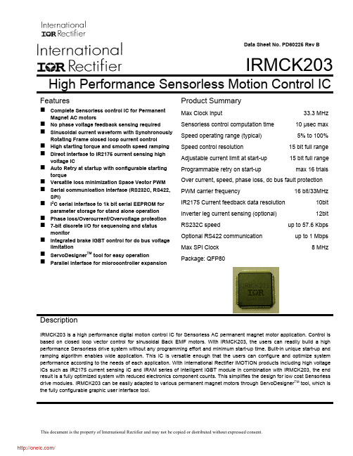
Data Sheet No. PD60225 Rev BIRMCK203High Performance Sensorless Motion Control ICFeaturesComplete Sensorless control IC for PermanentMagnet AC motorsNo phase voltage feedback sensing required Sinusoidal current waveform with SynchronouslyRotating Frame closed loop current control High starting torque and smooth speed ramping Direct interface to IR2175 current sensing highvoltage IC Auto Retry at startup with configurable startingtorque Versatile loss minimization Space Vector PWM Serial communication interface (RS232C, RS422,SPI) I 2C serial interface to 1k bit serial EEPROM forparameter storage for stand alone operation Phase loss/Overcurrent/Overvoltage protection 7-bit discrete I/O for sequencing and statusmonitorIntegrated brake IGBT control for dc bus voltage limitation ServoDesigner TM tool for easy operationParallel interface for microcontroller expansionProduct SummaryMax Clock input33.3 MHz Sensorless control computation time 10 µsec max Speed operating range (typical) 5% to 100% Speed control resolution15 bit full range Adjustable current limit at start-up 15 bit full range Programmable retry on start-upmax 16 trialsOver current, speed, phase loss, dc bus fault protection PWM carrier frequency16 bit/33MHzIR2175 Current feedback data resolution 10bit Inverter leg current sensing (optional) 12bitRS232C speedup to 57.6 Kbps Optional RS422 communication up to 1 MbpsMax SPI Clock 8 MHzPackage: QFP80DescriptionIRMCK203 is a high performance digital motion control IC for Sensorless AC permanent magnet motor application. Control is based on closed loop vector control for sinusoidal Back EMF motors. With IRMCK203, the users can readily build a high performance Sensorless drive system without any programming effort and minimum start-up time. Built-in unique start-up and ramping algorithm enables wide application. This IC is versatile enough that the users can configure and optimize system performance according to the needs of each application. With International Rectifier iMOTION products including high voltage ICs such as IR2175 current sensing IC and IRAM series of Intelligent IGBT module in combination with IRMCK203, the end result is a fully optimized system with reduced electronics component counts. This simplifies the design for low cost Sensorless drive modules. IRMCK203 can be easily adapted to various permanent magnet motors through ServoDesigner TM tool, which is the fully configurable graphic user interface tool.OverviewIRMCK203 is a new International Rectifier integrated circuit device designed for one-chip solution for complete closed loop current and velocity control of a high performance Sensorless drive for PM motors. Unlike a traditional microcontroller or DSP, IRMCK203 does not require any programming to complete complex Sensorless algorithm development. Combined with International Rectifier's high voltage gate drive and current sensing IC, the user can implement complete speed control of PM motors with minimum component count and virtually no design effort. In addition to Sensorless closed loop speed control operation, features such as Start-up retry, Phase Loss detection, Low Loss PWM, Regeneration Braking control and various drive protections are all implemented inside IRMCK203. Analog and digital I/Os can also be configured. Host communication logic contains Asynchronous Communication Interface for RS232C or RS422 communication interface, a fast slave SPI interface and an 8 bit wide Host Parallel Interface. All communication ports have the same access capability to the host register set. The users can write to, and read from the predefined registers to configure and monitor the drive through these communication ports.IRMCK203 Main functions• Complete closed loop current control based on Synchronously Rotating Frame Field Orientation (using Rotor Angle Observer)• Closed loop velocity control based on estimated speed• Configurable parameters (PI controller gains, PI output limit range, current feedbackscaling, PWM carrier frequency) provide adaptation to various PM motors• Built-in Sensorless control logic for start-up, ramping, and running conditions• Auto Retry (programmable) on start-up with configurable torque current limit• Analog reference input (can be used for speed reference)• RS232C/RS422 reference input• Full dynamic braking control for DC bus voltage limitation• Cycle-by-cycle on/off Control for Brake IGBT• Loss minimization Space Vector PWM with deadtime insertion• Build-in two IR2175 current sensing IC interfaces• Phase Loss, Overcurrent (GATEKILL input), Overvoltage, Undervoltage, Overspeed protection• Low cost serial 12bit A/D interface with multiplexer and sample/hold circuit• Optional Inverter Leg (low side) current sensing in lieu of IR2175 IC• 4 channel analog output (PWM)• Local EEPROM for startup initialization of internal data/parameters through host register interface AT24C01A, 128X8• Versatile host communication interfaceRS232C or RS422 host interfaceFast SPI slave host interface with multi-drop capabilityParallel Host interface (total 12 pins)• Multiplexed data/address busAddress EnableRD/WR• Discrete I/Os for Standalone mode operationSTARTSTOP (Input)ESTOP (Input)DIR (Input) FLTCLR (Input) FAULT (Output) SYNC (Output) REDLED (Output)GREENLED (Output)Table of Contents Overview (2)IRMCK203 Main functions (2)IRMCK203 Block Diagrams (7)Basic Block Diagram (7)Input/Output of IRMCK203 (8)Application Connections (12)IC Crystal Clock Circuitry (13)PLL Clock Circuitry (14)Low Pass Filter (14)Implementing the Low Pass Filter Shield (15)Cp Rp and Cs Component Values (15)PLL Reset (15)DC Electrical Characteristics and Operating Conditions (16)Absolute Maximum Ratings (16)Recommended Operating Conditions (16)DC Characteristics (17)Common Quiescent and Leakage Current (17)Input Characteristics – Non Schmitt Inputs (17)Input Characteristics – Schmitt Inputs (17)Output Characteristics (17)Output Characteristics OSC2CLK (18)Pin and I/O Characteristic Table (19)Power Consumption (21)AC Electrical Characteristics and Operating Conditions (22)System Level AC Characteristics (22)Sync Pulse to Sync Pulse Timing (22)FAULT and REDLED Response to GATEKILL (23)Host Interface AC Characteristics (24)SPI Timing (24)Host Parallel Timing (25)Host Parallel Read Cycle (25)Host Parallel Write Cycle (26)Discrete I/O Electrical Characteristics (27)Motion Peripheral Electrical Characteristics (28)PWM Electrical Characteristics (28)IR2175 Interface (28)Analog Interface Electrical Characteristics (29)ADC Timing (29)PLL Interface Electrical Characteristics (30)Appendix A Host Register Map (31)Register Access (31)Host Parallel Access (31)SPI Register Access (31)RS-232 Register Access (31)Write Register Definitions (36)PwmConfig Register Group (Write Registers) (36)CurrentFeedbackConfig Register Group (Write Registers) (37)SystemControl Register Group (Write Registers) (38)TorqueLoopConfig Register Group (Write Registers) (38)VelocityControl Register Group (Write Registers) (39)IRMCK203 FaultControl Register Group (Write Registers) (40)SystemConfig Register Group (Write Registers) (41)EepromControl Registers (Write Registers) (42)ClosedLoopAngleEstimator Registers (Write Registers) (43)OpenLoopAngleEstimator Registers (Write Registers) (44)StartupAngleEstimator Registers (Write Registers) (44)StartupRetrial Registers (Write Registers) (45)PhaseLossDetect Registers (Write Registers) (47)D/AConverter Registers (Write Registers) (47)Factory Test Register (Write Register) (48)Read Register Definitions (49)SystemStatus Register Group (Read Registers) (49)DcBusVoltage Register Group (Read Registers) (49)FocDiagnosticData Register Group (Read Registers) (50)FaultStatus Register Group (Read Registers) (51)VelocityStatus Register Group (Read Registers) (52)CurrentFeedbackOffset Register Group (Read Registers) (53)EepromStatus Registers (Read Registers) (53)FOCDiagnosticDataSupplement Register Group (Read Registers) (54)ProductIdentification Registers (Read Registers) (55)Factory Register (Read Register) (55)Appendix B Package (56)Table of FiguresFigure 1: IRMCS2031 Simplified Blocks (7)Figure 2: Input/Output of IRMCK203 (8)Figure 3: Application Connection of IRMCK203 (12)Figure 4: Oscillator Circuit (13)Figure 5: PLL Low Pass Filter Shielding (14)Figure 6: System Level SYNC To SYNC Timing (22)Figure 7: FAULT and REDLED Response to GATEKILL (23)Figure 8: SPI Timing (24)Figure 9: Host Parallel Read Cycle (25)Figure 10: Host Parallel Write Cycle (26)Figure 11: Discrete I/O Timing (27)Figure 12: PWM Timing (28)Figure 13: IR2175 Interface (28)Figure 14: Top Level ADC Timing (29)Table of TablesTable 1: Typical Values for the Clock Circuit (13)Table 2: PLL Test Pin Assignments (14)Table 3: PLL Low Pass Filter Values (15)Table 4: Absolute Maximum Ratings (16)Table 5: Recommended Operating Conditions (16)Table 6: DC Characteristics (17)Table 7: Non Schmitt Input Characteristics (17)Table 8: Schmitt Input Characteristics (17)Table 9: Output Characteristics (17)Table 10: Output Characteristics OSC2CLK (18)Table 11: Pin and I/O Characteristics (21)Table 12: IRMCK203 Power Consumption (21)Table 13: System Level SYNC to SYNC Timing (22)Table 14: FAULT and REDLED Response to GATEKILL (23)Table 15: SPI Timing (24)Table 16: Host Parallel Read Cycle Timing (25)Table 17: Host Parallel Write Cycle Timing (26)IRMCK203 Block DiagramsBasic Block DiagramFigure 1 shows the basic block diagram of the IRMCK203 surrounded by International Rectifiers’ ICs. Host communications are provided over SPI, RS-232C or Host parallel ports. Two current sensing ICs (IR2175) and a three phase high voltage gate drive typically implement the high voltage / current interface between the IRMCK203 IC and motor.The IRMCK203 can operate in a “stand-alone” mode without the host controller. A serial EEPROM would be utilized to load motor-specific parameters into the IC.AC PowerConfigurable parameters are provided to tailor design to various applications (motor and load). These configurable parameters can be modified via the host register interface through the communication interface. In the IRMCK203 product, a design spread sheet is provided to aid the user for ease of drive start-up, the spread sheet will input high level application data such as motor name plate information, max speed, current limit, speed and current regulator bandwidth, base on this information the program will generate the required configurable parameters. Detail on Drive commissioning is described in the IRMCK203 Application Developer’s Guide.All logic and algorithms are pre-programmed, and the user does not need to make any effort to develop code, alleviating the tedious design process. If needed, the user can configure the drive to tailor the control per specificneeds to meet the required specification. This configuration can be easily done by accessing the host register interface through the communication interface.Input/Output of IRMCK203The I/O signals are shown in Figure 2. The interface signals are divided into sub-groups. For detailed pin assignment, please refer to appendix (Pin definition).PWMUH PWMUL PWMVL BRAKEGATEKILLIFB[0-1]ADCLK ADOUT ADCONVST ADMUX[0-2]RESSAMPLEPWM gate signalInterfaceIR2175 Interface A/D InterfaceSPI Interface Parallel InterfaceLED/StatusPLL Clock ControlCrystalDAC[0-3]D/A Interface (PWM output)RESETNSystem ResetFLTCLROUT Figure 2: Input/Output of IRMCK203Host Interface GroupSignal Input (I) /Output (O)Low (L) /High (H) TrueAsserted FunctionSPICLK IPositive edgesensitiveSPI clockSPIMISO O - Master input and slave output SPIMOSI I - Master output and slave input SPICSN I L SPI chip selectHP_nOE I LParallel data output enable HP_nWE I LParallel data write cycleidentificationHP_D [7:0] I/O - Parallel dataHP_A I HParallel data address cycleidentificationHP_nCS I L Chip select TX O - RS-232 data out RX I - RS-232 data inBAUDSEL[1:0] I H RS-232 baud rate: 00 = 19.3K bps;01 = 38.4K bps10 = 57.6K bps;11 = 1.031250M bpsSYNC O L Start of PWM cycleCLK1XOUT O -33.333 MHz output of PLL. This signal has no phase relationshipwith the OSC1CLK or OSC2CLK inputs.Discrete I/O GroupSignalInput (I) / Output (O)Low (L) / High (H) True AssertedFunctionSTARTSTOP I HStart / Stop command edgesensitiveDIR I HForward/Reverse Directioncommand, level sensitiveFAULTCLR I H Fault ClearESTOP I HEmergency Stop, statesensitivePWEN O H PWM enable/disable state SYNC O H SYNC pulse FAULT O H Fault stateMotion Peripheral GroupSignalInput (I) / Output (O)Low (L) / High (H) True AssertedFunctionPWMUH O PWM phase U high side PWMUL O PWM phase U low side PWMVH O PWM phase V high sidePWHVL O PWM phase V low side PWMWH O PWM phase W high side PWMWL O -PWM phase W low side BRAKE O L IGBT gateGATEKILL I Varies, Based onWrite Register0x0C Bit 7When asserted, negates all sixPWM signals, host writeableIFB0 I - Channel 0 (phase V) IFB1 I - Channel 1 (phase W)Analog Interface GroupSignal Input (I) /Output (O)Low (L) /High (H) TrueAsserted FunctionADCLK ONegative EdgeSensitiveClock to ADS7818ADOUT I - Serial data from ADS7818 DAC [3:0] O - Diagnostic DACADCONVST O LConversion start to ADS7818 RESSAMPLE OSample/hold control signalchannel 0 A/D converterADMUX0 O H Analog input MUX select ADMUX1 O H Analog input MUX selectPLL Interface GroupSignal Input (I) /Output (O)Low (L) /High (H) True AssertedFunctionXPD I L PLL reset RESETN I L Digital logic resetBYPASSCLK I HInternal test pin – force to logiclowBYPASSMODE I HInternal test pin – force to logiclowOSC1CLK I - 33.33 MHz crystal input OSC2CLK I - 33.33 MHz crystal inputPLLTEST I HInternal test pin – force to logiclowCHGO I/O - Low pass filter LPVSS I/O - Low pass filter ground分销商库存信息: IRIRMCK203。
ZEBRA使用说明

斑馬Z4M打印機使用手冊一、Zebra Z4M 条码打印机参数说明工业级条码打印机,结实耐用的压铸金属外壳强大的实时连接,卓越的兼容性,低廉的价格适应工业现场使用的需要,满足工业高品质打印的要求详细参数打印机规格:打印方式:热转印/热敏方式打印分辨率:203dpi (8点/mm) /300dp(12点/mm)最大打印宽度:104mm(z4m)/168mm(z6m)最大打印长度:2667mm(203dpi)/1245mm(300dpi标准内存 )打印速度:254mm/秒(203dpi) /152mm/秒(300dpi)物理特性:z4m:宽 278毫米 ×长 475毫米 ×高 338毫米z6m:宽 341毫米 ×长 475毫米 ×高 338毫米净重:15 公斤(z4m)/16公斤(z6m)结构:全金属结构产品特性:标准内存:4MB DRAM (2MB用户使用)32位RISC微处理器Zebra 的 E3 打印元件控制技术穿透式传感器自动测纸认证:UL 1950;CISPR 22 (Class B);IEC 950; 801-2, -3 and -4 standards;Canadian Doc. (Class A);FCC (Class B);CE compliance选配:升级至2MB FLASH 存储器或通过PCMCIA卡升级到8MB FLASH 软件:ZPL II 编程语言条形码:一维条码:Code 11, UPC-A, UPC-E,Industrial 2 of 5 , Code 39,EAN-8, EAN-13,LOGMARS,Code 93,Plessey,Postnet ,Code 128 with subsets A/B/C and UCC Case Codes,Interleaved 2 of 5,EAN and UPC with 2 or 5 digit supplements,Codabar, Standard2 of 5,MSI, ISBT 128二维条码:CODABLOCK,PDF417,Code 49,Maxi Code,Data Matrix,QR Code使用环境:操作温度: 5℃-40℃操作湿度: 20%-85%存储温度: -40℃-60℃存储湿度: 5%-85%其他参数:电气参数:内置自动转换电源 90V-265V 48-62Hz 最大电流5A通讯接口:RS232/422/485接口及标准并口;IEEE1284双向并口准并口标签:宽度: 25.4 毫米 -114毫米长度:最大:991毫米最小:撕裂方式- 16mm;剥离方式-25mm;切刀方式-38mm 类型:连续型、膜切型、缺口型、黑标型、穿孔型最大直径:外径203mm,内径76mm间隙: 2mm-4mm厚度: 0.058-0.25mm碳带:标准长度:300m、450m,提供2:1或3:1标签卷宽度: 51-4.311mm卷轴内径:25mm卷轴最大直径: 81mm使用范围:运输商业医药卫生生产/物流政府/办公二、 Zebra Z4M条形码打印机使用及面板功能说明1〃标签与碳带的安装按图指示方向侧板上的突起线标为卷标和碳带安装路径。
- 1、下载文档前请自行甄别文档内容的完整性,平台不提供额外的编辑、内容补充、找答案等附加服务。
- 2、"仅部分预览"的文档,不可在线预览部分如存在完整性等问题,可反馈申请退款(可完整预览的文档不适用该条件!)。
- 3、如文档侵犯您的权益,请联系客服反馈,我们会尽快为您处理(人工客服工作时间:9:00-18:30)。
An affordable, host-based kiosk printer for 3-inch-wide receipts, Zebra’s compact KR203™ printer delivers unparalleled value andreliability for a variety of self-service applications. The KR203 draws upon the kiosk PC’s processing power and memory resources instead of its own, making it a highly cost-effective choice for customers who need a high-quality kiosk printer at the lowest total cost of ownership.In fact, the KR203 offers the best value in its class, providing high print quality and many features available only on more expensive printers. Designed to reduce theneed for maintenance or service by associates, it includes built-in troubleshooting capabilities; Zebra’s patented looping presenter and an integrated cutter for preventing paper jams; a tear-preventing pull detector; and a large, long-lasting, 10-inch/250 mm media roll capacity.This host-based printer is easy to integrate into your kiosk systems—it can print any font, barcode or graphics supported by your application. The printer’s small size and wide range of mounting configurations make it an easy fit for any kiosk design and perfect for Zebra’s Kiosk Print Station.KR200 Series Printers Offer:Unremitting Reliability to Keep Kiosks PrintingOptimized for tough printingenvironments where durability, reliability, minimal maintenance and ease of use are critical, Zebra printers maximize uptime and minimize upkeep.Easy to Integrate in Kiosk Designs A small footprint and flexible mounting options make our printers ideal for a variety of applications—whetherembedded in a custom kiosk solution or Zebra’s Kiosk Print Station.End BenefitsAs an integral part of a self-service kiosk solution, Zebra printers help companies improve service, raise customersatisfaction, increase revenue and lower operational costs.Zebra KR200 Series Data Sheet1*Specifications subject to change without notice.©2013 ZIH Corp. Zebra and the Zebra head graphic are registered trade m arks of ZIH Corp. All rights reserved. Windows, Windows Vista and Windows Server are either registered trademarks or trademarks of Microsoft Corporation in the United States and/or other countries. All other trademarks are the property of their respective owners.Corporate Headquarters +1 800 423 0442inquiry4@ Asia-Pacific Headquarters +65 6858 0722apacchannelmarketing@ EMEA Headquarters +44 (0)1628 556000mseurope@ Latin America Headquarters +1 847 955 2283inquiry4@P1033469 (03/13)Other Locations / USA: California, Georgia, Illinois, Rhode Island, T exas, Wisconsin Europe: France, Germany, Italy, the Netherlands, Poland, Spain, Sweden, Turkey, United Kingdom Asia Pacific: Australia, China, Hong Kong, India, Indonesia, Japan, Malaysia, Philippines, Singapore, South Korea, Taiwan, Thailand, Vietnam Latin America: Argentina, Brazil, Colombia, Florida (LA Headquarters in USA), Mexico Africa/Middle East: Dubai, South AfricaPrinter Name KR203Standard Features• Direct thermal receipt printing for 2.3”/58 mm to 3.25”/82.5 mm width media• Patented looping presenter with pull detector • Integrated cutter • Auto media loading• Horizontal and vertical mounting capability • Various media mounting options behind and below give flexibility to kiosk design, up to 9.8”/250 mm diameter media rolls • USB connectivity• 203 dpi print resolution• Windows ® drivers for plug and play• Prints any font, barcode and graphics supported by the application• Automatic and continuous status monitoring for media condition and errorsMaximum Print Width 3.1”/80 mmMinimum Print Length3.6”/92 mmMaximum Print Length 23.6”/600 mm Print Speed6”/152 mm per second Media SensorsOut-of-paper, paper in presenter, black mark, and input for external paper-low Media Characteristics Media Width2.3”/58 mm, 2.4”/60 mm,3.15”/80 mm and 3.3”/82.5 mm supported Maximum Roll Size 9.8”/250 mm Core Diameter1”/25 mm typical, 0.5”/12 mm with optional accessories Media Thickness0.002”/0.054 mm to 0.004”/0.11 mm Media Types Roll or fanfold paperOperating CharacteristicsEnvironmental• Operating T emp.: 32º F/0º C to 122º F/50º C • Storage T emp.: -22º F/-30º C to 149º F/65º C• Operating Humidity: 20% to 80% non-condensing • Storage Humidity: 10% to 95% non-condensing excluding paper Electrical24Vdc +/-5% average of 2A when printingPhysical Characteristics Embedded• Width: 4.2”/107 mm • Height: 2.7”/69 mm • Depth: 5.7”/145 mm • Weight: 2.4 lbs/1.1 kg Communication and Interface Capabilities • USBOperating SystemWindows ® 7, Windows Vista ®, Windows ® XP , Windows Server ® 2003, Windows Server ® 2008 (32 and 64 bit O/S support for all drivers)Options and Accessories• Media guides: 58, 60, 80 and 82.5 mm• Roll holder “universal” variable position, 7.9”/ 200 mm dia max• Adapter for roll holder below position, 9.8”/250 mm dia max• Roll holder wall mount, 5.9”/150 mm dia max • Quick fit hubs for easy mounting and removal of printer• Paper-low sensor with 11.8”/300 mm cable • Paper-low sensor with 19.7”/500 mm cable • Large media roll accessory to remove print artifacts from media rolls over 6”/150 mm in diameter• Adapter plate and spindle for 0.5”/12 mm media rolls• Output bezel for easier integration• Output shutter to protect the printer from intrusion or damage• Accessory kits for quick deploymentSPECIFICATIONS AT A GLANCE*。