蒂森M.3.8010204板端口定义说明
蒂森控制板操作器说明书

DIAGNOSTIC UNIT IFunction 01 00 Display of error stack as per:05.00显示故障堆栈 Example:ErrorExplanationWeighting BW任务特N emergency stop 紧急停梯 landing 楼层S stopping 停止undefined 未定义M spontaneous message 自发信息 explanations from page 21 解释21页B lift blocked 电梯被锁定ZZ Number of marking flag 标志编号..B operation phase 运行阶段Significance: Frequency levels of error: 含义:故障频繁度Level 1 infrequent 1度不频繁1) can be suppressed with switch 6S1 on circuit board MZ or with switch S5 on circuit board MZ1.1) Dependenton the function involved, reset can either mean emergency stop following by adjusting run or stopping of the lift installation2) Handshake is defined as cyclical data exchange (telegram) between two data carriers.1) SR module can be masked out via teach-in mode function AF 0d. Running-open operation and re-levelling with door open is not possible.1) Error from TCI work program 03.89/7 – no longer used.2) Error 35 00 and 3b 00 can no longer occur from work program 02.87/4 and error 36 00 can no longer occur from 06.95/25.1) SR module can be masked out through teach-in-mode function AF 0d. N Runnin-open operation andre-levelling with open door not possible.2) 0C 04 to 0C 0C leads also to stopping, if not provided otherwise in the lift-specific EPROM !1) If errors 65 00 to 74 00 occur more than 3 times, error 4F 00 will follow afterwards, which leads tospontaneous message and stopping1) DSP is the digital signal processor in the CPI controller2) Handshake is defined as cyclical data exchange (telegram) between two data carriers.Explanations of the existing error code numbers04 NN TCI control – Interrogation of ZSE solenoid switchesNN is represented as a hexadecimal number; in the event of errors, it indicates the number of ZSE switches (no other than the ZSE switch of the car position may be actuated).04 00 applies to ZSE 25 t o ZSE 3104 00 applies to ZSE 17 t o ZSE 2404 00 applies to ZSE 9 to ZSE 1604 0C applies to ZSE 1 to ZSE 8Example: 0 4 0 CHexadecimal number 0C∣∣Binary number 0 0 0 0 1 1 0 0∣∣∣∣∣∣∣∣assigned ZSE switch 8 7 6 5 4 3 2 1The example shows that ZSE switches ZSE3 and ZSE4 (in 3. and 4. landing) havebeen activated. (Also compare hexadecimal code in part 4, page 2)04 NN TCM control – Interrogation of ZSE solenoid switchesIf ZSE switches are closed in the third and fourth landing, the TCM controlwill file two errors: 04 03 und 04 0406 XX TCI control–Door locking not possible (from work program version 08.91/9)The lift will be put out of service for 15 min. after 3 unsuccessful doorlocking attempts. A new locking attempt will be initiated after expiry ofthis period of time.XX = StandortDoor variant – hinged door:A new locking attempt will also be made within these 15 min. after opening ofthe landing door (TK open) and closingit again (TK closed).Door variant D4 (with mechanical locking device)A start attempt will be enabled within 15 min., as soon as the controlreceives the bolt contact.06 XX TCM control–Door locking not possibleIf open bolt contact is recognized in the command chain preceding theposition the following error will follow14 XX (XX = bolt contact main side)18 XX (XX = bolt contact rear side)09 NN Car will be blocked in the landing >4 minExample LED Signal name (LED display on diagnostic unit Irow A)0 KKD0 LSD1 KK O.K.1 LS O.K.0 TSUD0 TSOD0 TSU1 TSO activatedFor LEDs and signal names see Operating Instructions of Diagnostic Unit I,function 05 00, column 0d (display of predefined memory locations, from page25).19 NN Door zone not detectedExample 1 9 C 81 VR1 A5A0 TO0 TU1 FL0 FS0 FO0 FUIn the operation phase STOP (lift at standstill), the CPU recognizes that thedoor zone calculated from the landing vanes was left.For LEDs and signal names see Operating Instructions Diagnostic Unit Ifunction 05 00, column 05 (display of predefined memory locations,from page25)1d NN Emergeny stop (wrong run direction)No run direction or both run directions were produced with the run contactoractivated and the brake disengaged.For LEDs and signal names see Operating Instructions, Diagnostic Unit I,function 05 00, column 05 (display of predefined memory locations from page25).In case of error 1d C8 the processor outputs the signals VR, A5A and FL (butwithout run directions); compare above representation of error 19 NN1E NN Deceleration not effectiveBinary display of car positionIt will be examined whether deceleration has been initiated already onreaching the marked terminal landing vanes.The position is indicated by the five bitst 20 to 25 as binary number.Example:27FO (run direction UP)26FU activated (run direction DOWN)252423Position (hexadecimal number converted into22binary number)211 201 E 9d: bits 20 to 27 stand for landing 29, therefore only run direction UPexists, since 26 = 0 and 27 = 1, and consequently 9 d will follow.Function 02 00 Display of order number (fromTCI work program version 06.88/6 and with TCM)显示定单号码(从TCI 06.88/6版工作程序起以及TCM梯)Example: Order No.: 27 70 06 42 10∣∣∣∣∣LED 5 12 3 10 1B A B A BFunction 03 00 Position indicator (decimal)楼层显示(十进制)Function 04 00 Operation phaseFunction 05 00 Display of specified memory locations1) Set function 05 00 with program selector wheel2) Press start-stop button3)Select desired column in 7-segment display with program selector wheelExample: Column 0d is desired. For example, select 0C 0d in 7-segment display, then left LED row B applies to column 0C and right LED row A applies to column0d, etc.4) Interrogate LED display (compare overview and signal description)5) Exit: press start-stop button for longer than 2 s.The LEDs listed in the table will light on selecting the respective column (Col) :1) Error markingExtension of columns for TCM control with MC1 or MC2 circuit boards1) pulses are counted dependent on the run direction (20 to 27 is displayed in LED row A/B)1) will be displayed as hexadecimal number in LED row A. Example: 09 in LED row A LEDs 0000 1001 light up2) displays last failure before current failure cause column 2C. Is displayed in hexadecimal numbers as in column 2C1) MF3 (VA) stands for circuit board MF3 with double-sided insertion 1) MF3 (VA) stands for circuit board MF3 with double-sided insertion1) MF3 (VA) stands for circuit board MF3 with double-sided insertion1) not assigned currently.Function 07 00 Display of parameters of CPI controller (only with TCM controls) 显示CPI。
蒂森轿内控制主板MF3-S技术说明书

版本:A 更改码:00 蒂森克虏伯电梯(上海)有限公司MF3-S 技术说明书TE036-SM生效日期:6/13/20061 概述参考MA12/6510/70 TCM Single-Board Lift Control MC2等相关文档;MF3为TCM-MC2系统中的轿厢控制板。
根据我工厂实际情况及市场实际需求,MF3-S 为在MF3的基础上,本地化设计的产品。
2 特性描述2.1 电源输入:典型使用 24VDC ;2.2 工作电压范围DC 9~40V;2.3使用功耗:不包括输入/输出,24VDC 电压输入时,小于等于50mA;3 功能描述3.1CAN BUS 通信:MF3-S 与TCM 主板(如MC2)进行实时的CAN BUS 串行通信,以交互轿厢控制与电梯控制主板(如TCM-MC2)之间的数据;3.2 内召按钮控制:MF3-S 已设计1-8层站的召唤按钮控制,如电梯高于8层站的情况,需MF4-S 板进行扩展;3.3 轿内显示控制:MF3-S 板解码来自主板的CAN BUS 数据包,再通过特定的数据接口,以向轿内显示板(如GMA9-S )提供正确的显示信息;3.4 轿内输入/输出信号:MF3-S 板上提供一些基本的输入信号,MF3-S 处理后发送给电梯控制主板,以如轿内基本操作信号:轿内优先、检修上/下、开关门到位等;同时MF3-S 也设计了一些基本的输出信号,MF3-S 通过CAN-BUS 接收控制主板信息,并正确输出,如超载运行、开/关门信号、上/下到站钟等等。
版本:A 更改码:00蒂森克虏伯电梯(上海)有限公司MF3-S 技术说明书TE036-SM生效日期:6/13/20064 线路板安装及布局图版本:A 更改码:00蒂森克虏伯电梯(上海)有限公司MF3-S 技术说明书TE036-SM生效日期:6/13/2006版本:A 更改码:00蒂森克虏伯电梯(上海)有限公司MF3-S 技术说明书TE036-SM生效日期:6/13/20065 MF3-S 软件配置MF3-S 软件配置与MF3板完全兼容,即配用27C256存储芯片,工作程序根据最新释放版本,其中前后门由软件来定义,于我工厂电气车间进行烧录;版本:A 更改码:00蒂森克虏伯电梯(上海)有限公司MF3-S 技术说明书TE036-SM生效日期:6/13/20066 MF3-S 接口定义列表6.1接口类型中,表示方法: “I ”- 输入;“O ”-输出;“C ”- CAN BUS ;“M ”- 综合;“P ”- 电源信号功能信号名称端口定义 接插件 类型 接口 类型备注1-8层召唤按钮控制 Car call button 1-8层按钮输入 0V+24 V1-8按钮灯输出 X51:3-X58:3X51:4-X58:4 X51:1-X58:1 X51:2-X58:2 CH2.54 × 4I轿内优先控制Preference V 0V+24V X34:3 X34:4 X34:1 CH2.54× 4 I满载信号Occupied B 0VX15:1 X15:2 CH3.96 × 2 I 超载Overload UB 0VX9:2CH3.96 × 2 I开门按钮Door opening Button OT 0V+24V X59:3 X59:4 X60:1 CH2.54 × 4 I关门按钮Door closing button UT 0V +24VX60:3 X60:4 X60:1 CH2.54 × 4 I再平层传感器Re-leveling Sensor LN +24V0V X42:2 X42:1 X42:3 CH3.96 × 3 I检修上/下Insp. op UP Insp, op DOWN IF IFO IFU 0VX40.1 X40.2 X40.3 CH3.96 × 3 I安全触板/光幕Articulated Light barrier d. KK 0V L TX5:1 X5:2 X5:3 CH3.96 × 3 I光电选层器Selector Sensor LK +24V0VX2:2 X2:1 X2:3 CH3.96 × 3 I后门安全触板/光幕 Articul. lever Rear Light barrier KKD 0V L TDX6:1 X6:2 X6:3CH3.96 × 3I版本:A 更改码:00蒂森克虏伯电梯(上海)有限公司MF3-S 技术说明书TE036-SM生效日期:6/13/2006MF3-S 接口定义列表(续一)信号功能信号名称端口定义 接插件 类型 接口 类型备注根据工作程序指定的备用输入EBS10V ZTK X41:1 X41:2 X41:1 CH3.96 × 2 I前门开门到位Door open switch (Front)TSO 0V X3:1 X3:2 CH3.96 × 2 I后门开门到位Door open switch RearTSOD 0V X4:1 X4:2 CH3.96 × 2 I备用输入EES2 0V X47:1 X47:2 CH3.96 × 2 I召唤屏蔽使能Coding of calls AT 0V+24VX49;3 X49:4 X49:1 CH2.54 × 4I轿内显示板数据端Dataindicator MA/3TSData to MA X35M前门开/关门信号Door open/close .sig. (m.door)TU TO X43:1 X43:2 CH3.96 × 2 O后门开/关门信号Door open/cLose signal, rear side TUD TOD X45:1 X45:2 CH3.96 × 2 O前门强迫关门信号 Nudging main side ZTZ +24V X44:2 X44:1 CH3.96 × 2 O 后门强迫关门信号 Nudging rear side ZTZD + 24V X46:2 X46:1 CH3.96 × 2 O下到站钟输出 Gong, BOTTOM I < 600 mA GU +24V X22:2 X22:1 CH3.96 × 2 O上到站钟输出 Gong, top I < 600 mAGO + 24VX19:2 X19:1 CH3.96 × 2 O消防警示钟Fireman’s horn I < 600 mAFEH + 24V X21:2 X21:1CH3.96 × 2O版本:A 更改码:00蒂森克虏伯电梯(上海)有限公司MF3-S 技术说明书TE036-SM生效日期:6/13/2006MF3-S 接口定义列表(续二)信号功能 信号名称 端口定义 接插件 类型 接口 类型备注紧急呼叫信号 Call alarm I < 600 mA RW + 24V X20:2 X20:1 CH3.96 × 2 O备用3 RES3 I < 40 mA RES3X62:2 X62:1 CH3.96 × 2 O备用4 RES4 I < 40 mA RES4 +24VX63:2 X63:1 CH3.96 × 2OCAN BUS 总线 CAN bus HIGH CAN bus LOW Front + rear coding CAN-H CAN-L 0V COD X64:4 X64:3 X64:2 X64:1 CH2.54 × 4C信号同X65CAN BUS 总线 CAN bus HIGH CAN bus LOW Front + rear coding CAN-H CAN-L 0V COD X65:1 X65:2 X65:3 X65:4 CH3.96 × 4C信号同X64电源电压Voltage supplyVoltage supply+24V 0VX1:1 X1: 2 CH3.96 × 2 P Voltage supply Command accept + 24V 0V X31:1 X31:2CH3.96 × 2P批 准审 核编 制。
蒂森MC2MC2系统主板通讯板端子介绍培训

蒂森MC2MC2系统主板通讯板端⼦介绍培训⽬录1.MC2主板端⼦介绍2. MF3轿厢通讯板端⼦介绍3. MF4通讯扩展板端⼦介绍4.MP板端⼦介绍5.MN6电源盒说明6. MH2说明1.MC2主板端⼦介绍MC2电路板端⼦介绍插头分配MC=输⼊/输出由 MC 部分控制。
MZ=输⼊/输出由 MZ 部分控制。
类型E=配置的输⼊A=配置的输出(除⾮另有规定,在 I≤40mA时可装⼊)标识插头孔销类型信号备注RS232诊断监控接⼝X11-未使⽤2E RXD收到的数据3A TXD传送的数据4-未使⽤5-GND(接地)6-未使⽤7-未使⽤8-未使⽤9-未使⽤诊断仪调试接⼝X21A+5V2A+5V3-GND(接地)4-GND(接地)5E输⼊端⼝1,位 06E输⼊端⼝1,位 17-未使⽤8-未使⽤9E输⼊端⼝1,位 410E输⼊端⼝1,位 511E输⼊端⼝1,位 612-n.c.12-n.c.13A输出端⼝1,位 014A输出端⼝1,位 115A输出端⼝1,位 216A输出端⼝1,位 317A输出端⼝1,位 418A输出端⼝1,位 519A输出端⼝1,位 620A输出端⼝1,位 7本地总线X31E/A CAN-H2E/A CAN-L3-GND(接地)标识插头孔销类型信号备注群控总线并联X41E/A CAN-H2E/A CAN-L3-GND(接地)驱动CPI X51-未使⽤2-未使⽤3A+24V4A SWF5E Channel A(槽道A)A 脉冲6E Channel B(槽道B)B 脉冲7-0V8E/A CAN-L本地总线9-未使⽤10E STR11A FO12A+5V13E Channel A(槽道A)*A 脉冲14E Channel B(槽道B)*B 脉冲15E/A CAN-H本地总线旋转脉冲(减速的及液压的)X61A+24V2A+12V3E Pulses(脉冲)4-GND(接地)额外串⾏接⼝X71A+24V2E+12V(V)3A Pulses(脉冲)4-GND(接地)液压式驱动X81A+24V输出 I≤40mA 2A V2备⽤输出 1,X39:23A V14A FO FO←MC(V0)5A FJR FJR←MZ(V)6A FUR FUR←MZ(向下)7A FOR FOR←MZ(向上)7A FOR FOR←MZ(向上)8A FLR FLR←MZ(V2)9A FSR FSR←MZ10-平稳启动完成(启动)11E STR STR(X5:10)12-0V标识插头孔销类型信号备注平稳启动X91A SWF SWF←MC2平稳启动完成主板电源5V X101E+5V2GND(接地)主板电源 24V X111E+24V2GND(接地)额外串⾏接⼝X121A+5V2E R×D(TTL)3A T×D(TTL)4GND(接地)随⾏电缆(→MZ,MC,SR 模块)X131E ZS门区ZS-区域开关→SR 模块2A+24V24V3-0V0V4E LK1平层开关LK1-光幕选择器 1→MC5E LK平层开关LK-光幕选择器→MC连接轿厢通讯MF3.MF4板.LMS1称重板6E/A CAN-H井道总线→MZ 7E/A CAN-L井道总线→MZ井道总线主端前门外呼通讯X141A INIH初始化(站层号的编码)2E/A CAN-H井道总线3E/A CAN-L井道总线4-GND(接地)GND(接地)井道总线后进⼝端后门外呼通讯X151A INIH初始化2E/A CAN-H井道总线→MS2 等3E/A CAN-L井道总线→MS2 等4-GND(接地)GND(接地)附加作⽤的插头优选权X201A+24V2E V优选权温度监控X211A+24V2E V温度监控过载X221A+24V2EÜl过载启动抱闸X231A=24V2A VRB抱闸磁铁启动1.直接连接到平稳启动插头上。
蒂森电梯

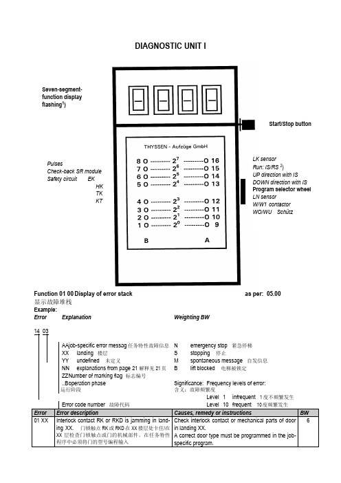
蒂森电梯I 型诊断仪7 段数字显示屏起动/停止按键(闪烁 1)旋转脉冲LK 传感器运行:IS/RS 2IS 上行 SR 模块反馈 IS 下行程序选择旋钮安全回路 EKLN 传感器HKTK W/W1 接触器 KTWO/WU 接触器当 I 型诊断仪没有进入 15AF 功能时,LK 和 LN 感应器被井道码板遮挡时,诊断仪上的 LK 和LN 相应的发光二极管闪烁。
当 I 型诊断仪进入 15AF 功能时,LK 和 LN 感应器被井道码板遮 挡时,诊断仪上的 LK 和 LN 相应的发光二极管不闪烁,并且在功能 15AF 里这两个 LED 的配位 也互相对换(见 MA13,类型 6510,顺序号 046)。
用诊断仪 I 总共可查询或处理 16 项功能。
用户可以通过程序选择旋钮选定各项功能。
选 定的功能出现在七段数字显示屏上(闪烁显示)。
使用方法将诊断仪 I 插入相关的印刷电路板(CPU ,门控制,LMS1 等等)。
显示屏显示某项功 能(闪烁)。
用户可调节程序选择旋钮,选择需要的功能。
只有在显示屏闪烁的情况下, 才能从一个功能转换到另一个功能。
退出选定功能:将程序选择旋钮旋转一档,然后按启动/停止键>2 秒。
用户可通过 AF00(dF00,bF00)或者将主开关切断再接通,退出教入功能。
本书中对诊断仪 I 的阐述或功能描述适用于 04.86.3 版起的所有工作程序。
TCI/TCM电 梯控制系统的现行工作程序将在紧急信息栏中公布。
诊断仪 I 的所有功能将在以下章节中分别作详细介绍。
1)当 七 段 显 示 屏 闪 烁 时, 上 图 侧 面 所 示 功 能 将 由 A 列 及 B 列 发 光 二 极 管 指 示 出来。
2)IS ... 检修运行 RS ... 应急电动运行。
诊断仪I(适用于电梯控制系统TCI和TCM)当TCI采用04.86/3版起的工作程序,TCM采用MC,MC1,MC2,MC3控制系统时,以下功能可供选择。
蒂森控制板操作器说明
DIAGNOSTIC UNIT IFunction 01 00 Display of error stack as per: 05.00 显示故障堆栈Example:Error Explanation Weighting BW14 03AAjob-specific error messag任务特性故障信息N emergency stop 紧急停梯XX landing 楼层S stopping 停止YY undefined 未定义M spontaneous message 自发信息NN explanations from page 21 解释见21页 B lift blocked 电梯被锁定ZZ N umber of marking flag 标志编号..B o peration phase 运行阶段Significance: Frequency levels of error:含义:故障频繁度Level 1 infrequent 1度不频繁发生Error code number 故障代码Level 10 frequent 10度频繁发生Error Error description Causes, remedy or instructions BW01 XX Interlock contact RK or RKD is jamming in land-ing XX. 门锁触点RK或RKD在XX楼层处卡住/在XX层检查门锁触点或门的机械部件。
在任务特性程序中必须将门的型号编程输入Check interlock contact or mechanical parts of doorin landing XX.A correct door type must be programmed in the job-specific program.6Start/Stop buttonLK sensorRun: IS/RS2)UP direction with ISDOWN direction with ISProgram selector wheelLN sensorW/W1 contactorWO/WU SchützSeven-segment-function display flashing1)PulsesCheck-back SR module Safety circuit EKHKTKKT1) can be suppressed with switch 6S1 on circuit board MZ or with switch S5 on circuit board MZ1.1) Dependenton the function involved, reset can either mean emergency stop following by adjusting run or stopping of the lift installation2) Handshake is defined as cyclical data exchange (telegram) between two data carriers.1) SR module can be masked out via teach-in mode function AF 0d. Running-open operation and re-levelling with door open is not possible.1) Error from TCI work program 03.89/7 – no longer used.2) Error 35 00 and 3b 00 can no longer occur from work program 02.87/4 and error 36 00 can no longer occur from 06.95/25.1) SR module can be masked out through teach-in-mode function AF 0d. N Runnin-open operation and re-levelling with open door not possible.2) 0C 04 to 0C 0C leads also to stopping, if not provided otherwise in the lift-specific EPROM !1) If errors 65 00 to 74 00 occur more than 3 times, error 4F 00 will follow afterwards, which leads to spontaneous message and stopping1) DSP is the digital signal processor in the CPI controller2) Handshake is defined as cyclical data exchange (telegram) between two data carriers.04 NN TCI control – Interrogation of ZSE solenoid switchesNN is represented as a hexadecimal number; in the event of errors, it indicates the number of ZSE switches (no other than the ZSE switch of the car position may be actuated).04 00 applies to ZSE 25 to ZSE 3104 00 applies to ZSE 17 to ZSE 2404 00 applies to ZSE 9 to ZSE 1604 0C applies to ZSE 1 to ZSE 8Example: 0 4 0 CHexadecimal number 0C∣∣Binary number 0 0 0 0 1 1 0 0∣∣∣∣∣∣∣∣assigned ZSE switch 8 7 6 5 4 3 2 1The example shows that ZSE switches ZSE3 and ZSE4 (in 3. and 4. landing) have been activated.(Also compare hexadecimal code in part 4, page 2)04 NN TCM control – Interrogation of ZSE solenoid switchesIf ZSE switches are closed in the third and fourth landing, the TCM control will file two errors: 04 03und 04 0406 XX TCI control–Door locking not possible (from work program version 08.91/9)The lift will be put out of service for 15 min. after 3 unsuccessful door locking attempts. A new lockingattempt will be initiated after expiry of this period of time.XX = StandortDoor variant – hinged door:A new locking attempt will also be made within these 15 min. after opening of the landing door (TKopen) and closingit again (TK closed).Door variant D4 (with mechanical locking device)A start attempt will be enabled within 15 min., as soon as the control receives the bolt contact.06 XX TCM control–Door locking not possibleIf open bolt contact is recognized in the command chain preceding the position the following error willfollow14 XX (XX = bolt contact main side)18 XX (XX = bolt contact rear side)09 NN Car will be blocked in the landing >4 minExample 0 9 3 1Signal name (LED display on diagnostic unit I row A)0 KKD0 LSD1 KK O.K.1 LS O.K.0 TSUD0 TSOD0 TSU1 TSO activatedFor LEDs and signal names see Operating Instructions of Diagnostic Unit I, function 05 00, column0d (display of predefined memory locations, from page 25).19 NN Door zone not detectedExample1 VR1 A5A0 TO0 TU1 FL0 FS0 FO0 FUIn the operation phase STOP (lift at standstill), the CPU recognizes that the door zone calculatedfrom the landing vanes was left.For LEDs and signal names see Operating Instructions Diagnostic Unit I function 05 00, column 05(display of predefined memory locations,from page 25)1d NN Emergeny stop (wrong run direction)No run direction or both run directions were produced with the run contactor activated and the brakedisengaged.For LEDs and signal names see Operating Instructions, Diagnostic Unit I, function 05 00, column 05(display of predefined memory locations from page 25).In case of error 1d C8 the processor outputs the signals VR, A5A and FL (but without run directions);compare above representation of error 19 NN1E NN Deceleration not effectiveBinary display of car positionIt will be examined whether deceleration has been initiated already on reaching the marked terminallanding vanes.The position is indicated by the five bitst 20 to 25 as binary number.Example: 1 E 9 d0 27FO (run direction UP)1 26FU activated (run direction DOWN)0 251 241 23Position (hexadecimal number converted into1 22binary number)0 211 201 E 9d: bits 20 to 27 stand for landing 29, therefore only run direction UP exists, since 26 = 0 and 27 =1, and consequently 9 d will follow.Function 02 00 Display of order number (fromTCI work program version 06.88/6 and with TCM)显示定单号码(从TCI 06.88/6版工作程序起以及TCM梯)Example: Order No.: 27 70 06 42 10∣∣∣∣∣LED 5 12 3 10 1B A B A BFunction 03 00 Position indicator (decimal)楼层显示(十进制)Function 04 00 Operation phase1) Set function 05 00 with program selector wheel2) Press start-stop button3)Select desired column in 7-segment display with program selector wheelExample: Column 0d is desired. For example, select 0C 0d in 7-segment display, then left LED row B applies to column 0C and right LED row A applies to column 0d, etc.4) Interrogate LED display (compare overview and signal description)5) Exit: press start-stop button for longer than 2 s.The LEDs listed in the table will light on selecting the respective column (Col) :1) Error marking1) pulses are counted dependent on the run direction (20 to 27 is displayed in LED row A/B)1) will be displayed as hexadecimal number in LED row A. Example: 09 in LED row A LEDs 0000 1001 light up2)displays last failure before current failure cause column 2C. Is displayed in hexadecimal numbers as in column 2C1) MF3 (VA) stands for circuit board MF3 with double-sided insertion 1) MF3 (VA) stands for circuit board MF3 with double-sided insertion1) MF3 (VA) stands for circuit board MF3 with double-sided insertion1) not assigned currently.显示CPI。
蒂森电梯培训

X1----X16 16个楼层按钮
BUS通迅端口 BUS通迅口
MA9轿厢显示板
MA9板
称重板
外呼板
蒂森I型诊断仪
蒂森变频器诊断仪PT
蒂森常用的调试
1,更换主板
I型诊断仪调试。 1) 下载芯片程序到主板
1500→确认→15AF→选择→15A6→确认→A6FF→ 选择→A60D(恢复原厂设置)→确认→A6FD(下 载特殊程序至主芯片内部存储器)→确认→A6EA→ 确认→A6DA→选择→A6AD(下载项目程序)→确 认→A600→确认→FC00(保存)。
蒂森常用的调试
2,更换CPIK变频器 3)P86主机编码器整定。 将I型诊断仪置于15AF。然后PT诊断仪进入 P86光标下移,将0→1,光标上移,TMI2板 工作指示灯由亮变灭,再等5秒左右,工作指 示灯点亮;光标下移,然后将1→2,。然后 按上/下行,正常的话,主机会动一下;松手 后,光标上移,数字2自动变为0。查看P105 显示编码器有多少个脉冲,一般是小于3个脉 冲的话,然后保存。
2,86XX故障 a)、抱闸电源不正常损坏,早期的MN6在电网 不稳定时有复位现象。 b)、K01,K01.1触头接触不良现象。 c)、MC2主板电压不稳,经监测开关返回到主 板X25/2/3的信号不正常。 d)、抱闸线圈接地线不良。 e)、抱闸检测开关调整不到位。 f)、抱闸自身工作不稳定,
蒂森常见故障处理
蒂森电梯基础培训
蒂森常见型号电梯的配件有
MC2主板
CPIK变频器
MF3板相关端口定义
X35:到MA9显示
版本苡片: 安装时注意安插方向
X2:平层信号检测 (一般不用)LK
X19:到站钟 X20::轿厢警报
X43:关门信号 X21:火灾报警
蒂森诊断仪--使用说明书
第 1 部 分 - 基 本 参 数 开门速度,mm/s. 关门速度,mm/s. 2 加速度,mm/s . 2 减速度 (正常),mm/s . 2 再开门时减速度,mm/s . 3 加加速度 (速度变化),mm/s . P 增益-速度控制器 (指示值 0.1). I 增益-速度控制器 (指示值 0.01). 显示爬行距离,mm. 爬行速度,mm/s. 强制关门速度,mm/s. 终点位置门的动作力,N. 终点位置门的动作力,N. 加速度预控制系数 (指示值 0.01). 0000 = 加速度预控制不起作用.
W erk Grenzach
教入开始
Technik u. Vertrieb Neuhausen
15 15
00 dF
将诊断仪插入 MW2 电路板,用程序选择轮选择并且操作按钮. 逆时针转动程序选择轮:可选择基本参数功能 dF 20 至 dF bF.
AGV Techn.Inc., Salt Lake City
W alther Rohrposttechnik GmbH, W esterstede (49%)
注意: 用 dF 0d 按按钮,则各个隐设值即自动地编入程序。这意味着所有特别输 入的值将 被删除。 只要更换了电路板 MW2 或是使用了新的软件,就要进行教入或是 dF 0d. 在各项教入功能完成之后,将显示 FE FE 作为完成信息。 输入隐设值 dF dF dF 0d 1d 01 操作按钮后,隐设值自动地编程输入。 当按钮操动之后,只有各项来自变参数模式第 1 第 2 部分的功 能, 会 作为隐设值被设定。 显示门的前缘的额定行程 -非中分门的门宽 TB,以 mm 计。 -中分门的半门宽 TB/2,以 mm 计。 修改额定行程。 完成信息。 将门移动到它的开门终端位置并操作按钮。用手将开着的门移动到它的关 门终端位置并操作按钮。 完成信息。 显示每 mm 行程的脉冲数-额定值-61 脉冲/mm。 36/100 = 概略低限/高限 0000 = 尚未教入 F000 = 不可取,即门宽输入错误或每 mm 脉冲数教入不正确. 显示电动机安装位置,左/右。 0001 = 左 0002 = 右 0000 = 尚未教入 操动按钮并沿某方向转动程序选择轮,使开着的门关闭。这样做时将弹簧 秤装到门的前缘处并继续转动程序选择轮,直到弹 簧秤指示 150 N. (如 果没有弹簧秤,可估计关门力 150 N = 手 动 15kg). 再操动按钮。 完成信息。 显示关门力矩极限值 (不是以 N 牛顿单位显示,而是以 % REAmax 显示, 1000 = REAmax)。 按按钮。教入的值将存入存储器,随即从教入功能 15 00 退出. 电路板 MW2 上的红色 LED 会瞬间发光。
蒂森诊断仪说明书
楼层码板: 感应器 LK 或 LK/LN 必须低于底层的楼层码板的平层缺口。
正常运行
带提前开门和 开门再平层时
*) 对于具有 50 mm 下越程的液压梯来说,将 LK 感应器移动到像正常运行那 样,开始教入运行。LN 感应器已插入。
感应器和脉冲发电机的 LED 必须发光 LK 感应器 A 列 LED 12 LN 感应器 A 列 LED 16 脉冲发电机 B 列 LED 8 (闪烁,例如轿厢用手轮移动时) 按动按钮将显示如下: AF 11 断开应急电动运行开关并按动按钮。轿厢向顶层运动,在此过程中 楼层间距离及楼层编码将被教入并存储, 在 FV 驱动装置时,电梯将以检修运行速度起动并自动转换到额定 速度,直到到达顶层的前一个楼层时再转换回检修运行速度,并在 顶层停止。 在较高质量的驱动装置 (Isostop 25M, Isostop 60) 中,电梯将以 再平层速度起动并且以检修速度运动穿过井道。 到达限位开关;井道信息被存入 EEPROM。此运行要求较长的一 段时间,特别 是,如果做所谓刷新 (当使用新的 EEPROM 或新的 CPU 时) 的话。 用 EE 0F 可将其显示在诊断仪上。
AF
0d
对 TCM 装置的 楼层编码 (参见 MA 12 6510.063 第 4 节)
0A 0b
XX XX
1A 1b
XX XX
注意: 隐设值在按按钮 AF 0d 时将被自动编入程序。这意味着所有的特别输入值因此将再度清除。 需要时,可再次编程修改隐设值。 只要更换了工作程序或者某块特定电路板,就一定要进行教入功能 AF 0d 或 AF 0C (TCM)。 在 TCI/TCM 控制装置中,按驱动装置型式不同,功能 AF 0d 只有在井道或速度教入后才会出 现.
蒂森控制板操作器说明
DIAGNOSTIC UNIT IFunction 01 00 Display of error stack as per: 05.00 显示故障堆栈Example:Error Explanation Weighting BW14 03AAjob-specific error messag任务特性故障信息N emergency stop 紧急停梯XX landing 楼层S stopping 停止YY undefined 未定义M spontaneous message 自发信息NN explanations from page 21 解释见21页 B lift blocked 电梯被锁定ZZ N umber of marking flag 标志编号..B o peration phase 运行阶段Significance: Frequency levels of error:含义:故障频繁度Level 1 infrequent 1度不频繁发生Error code number 故障代码Level 10 frequent 10度频繁发生Error Error description Causes, remedy or instructions BW01 XX Interlock contact RK or RKD is jamming in land-ing XX. 门锁触点RK或RKD在XX楼层处卡住/在XX层检查门锁触点或门的机械部件。
在任务特性程序中必须将门的型号编程输入Check interlock contact or mechanical parts of doorin landing XX.A correct door type must be programmed in the job-specific program.6Start/Stop buttonLK sensorRun: IS/RS2)UP direction with ISDOWN direction with ISProgram selector wheelLN sensorW/W1 contactorWO/WU SchützSeven-segment-function display flashing1)PulsesCheck-back SR module Safety circuit EKHKTKKT1) can be suppressed with switch 6S1 on circuit board MZ or with switch S5 on circuit board MZ1.1) Dependenton the function involved, reset can either mean emergency stop following by adjusting run or stopping of the lift installation2) Handshake is defined as cyclical data exchange (telegram) between two data carriers.1) SR module can be masked out via teach-in mode function AF 0d. Running-open operation and re-levelling with door open is not possible.1) Error from TCI work program 03.89/7 – no longer used.2) Error 35 00 and 3b 00 can no longer occur from work program 02.87/4 and error 36 00 can no longer occur from 06.95/25.1) SR module can be masked out through teach-in-mode function AF 0d. N Runnin-open operation and re-levelling with open door not possible.2) 0C 04 to 0C 0C leads also to stopping, if not provided otherwise in the lift-specific EPROM !1) If errors 65 00 to 74 00 occur more than 3 times, error 4F 00 will follow afterwards, which leads to spontaneous message and stopping1) DSP is the digital signal processor in the CPI controller2) Handshake is defined as cyclical data exchange (telegram) between two data carriers.04 NN TCI control – Interrogation of ZSE solenoid switchesNN is represented as a hexadecimal number; in the event of errors, it indicates the number of ZSE switches (no other than the ZSE switch of the car position may be actuated).04 00 applies to ZSE 25 to ZSE 3104 00 applies to ZSE 17 to ZSE 2404 00 applies to ZSE 9 to ZSE 1604 0C applies to ZSE 1 to ZSE 8Example: 0 4 0 CHexadecimal number 0C∣∣Binary number 0 0 0 0 1 1 0 0∣∣∣∣∣∣∣∣assigned ZSE switch 8 7 6 5 4 3 2 1The example shows that ZSE switches ZSE3 and ZSE4 (in 3. and 4. landing) have been activated.(Also compare hexadecimal code in part 4, page 2)04 NN TCM control – Interrogation of ZSE solenoid switchesIf ZSE switches are closed in the third and fourth landing, the TCM control will file two errors: 04 03und 04 0406 XX TCI control–Door locking not possible (from work program version 08.91/9)The lift will be put out of service for 15 min. after 3 unsuccessful door locking attempts. A new lockingattempt will be initiated after expiry of this period of time.XX = StandortDoor variant – hinged door:A new locking attempt will also be made within these 15 min. after opening of the landing door (TKopen) and closingit again (TK closed).Door variant D4 (with mechanical locking device)A start attempt will be enabled within 15 min., as soon as the control receives the bolt contact.06 XX TCM control–Door locking not possibleIf open bolt contact is recognized in the command chain preceding the position the following error willfollow14 XX (XX = bolt contact main side)18 XX (XX = bolt contact rear side)09 NN Car will be blocked in the landing >4 minExample 0 9 3 1Signal name (LED display on diagnostic unit I row A)0 KKD0 LSD1 KK O.K.1 LS O.K.0 TSUD0 TSOD0 TSU1 TSO activatedFor LEDs and signal names see Operating Instructions of Diagnostic Unit I, function 05 00, column0d (display of predefined memory locations, from page 25).19 NN Door zone not detectedExample1 VR1 A5A0 TO0 TU1 FL0 FS0 FO0 FUIn the operation phase STOP (lift at standstill), the CPU recognizes that the door zone calculatedfrom the landing vanes was left.For LEDs and signal names see Operating Instructions Diagnostic Unit I function 05 00, column 05(display of predefined memory locations,from page 25)1d NN Emergeny stop (wrong run direction)No run direction or both run directions were produced with the run contactor activated and the brakedisengaged.For LEDs and signal names see Operating Instructions, Diagnostic Unit I, function 05 00, column 05(display of predefined memory locations from page 25).In case of error 1d C8 the processor outputs the signals VR, A5A and FL (but without run directions);compare above representation of error 19 NN1E NN Deceleration not effectiveBinary display of car positionIt will be examined whether deceleration has been initiated already on reaching the marked terminallanding vanes.The position is indicated by the five bitst 20 to 25 as binary number.Example: 1 E 9 d0 27FO (run direction UP)1 26FU activated (run direction DOWN)0 251 241 23Position (hexadecimal number converted into1 22binary number)0 211 201 E 9d: bits 20 to 27 stand for landing 29, therefore only run direction UP exists, since 26 = 0 and 27 =1, and consequently 9 d will follow.Function 02 00 Display of order number (fromTCI work program version 06.88/6 and with TCM)显示定单号码(从TCI 06.88/6版工作程序起以及TCM梯)Example: Order No.: 27 70 06 42 10∣∣∣∣∣LED 5 12 3 10 1B A B A BFunction 03 00 Position indicator (decimal)楼层显示(十进制)Function 04 00 Operation phase1) Set function 05 00 with program selector wheel2) Press start-stop button3)Select desired column in 7-segment display with program selector wheelExample: Column 0d is desired. For example, select 0C 0d in 7-segment display, then left LED row B applies to column 0C and right LED row A applies to column 0d, etc.4) Interrogate LED display (compare overview and signal description)5) Exit: press start-stop button for longer than 2 s.The LEDs listed in the table will light on selecting the respective column (Col) :1) Error marking1) pulses are counted dependent on the run direction (20 to 27 is displayed in LED row A/B)1) will be displayed as hexadecimal number in LED row A. Example: 09 in LED row A LEDs 0000 1001 light up2)displays last failure before current failure cause column 2C. Is displayed in hexadecimal numbers as in column 2C1) MF3 (VA) stands for circuit board MF3 with double-sided insertion 1) MF3 (VA) stands for circuit board MF3 with double-sided insertion1) MF3 (VA) stands for circuit board MF3 with double-sided insertion1) not assigned currently.显示CPI。
蒂森控制板操作器说明审批稿
蒂森控制板操作器说明 YKK standardization office【 YKK5AB- YKK08- YKK2C- YKK18】DIAGNOSTIC UNIT IFunction 01 00 Display of error stackas per:显示故障堆栈 Example: Error Explanation Weighting BW14 03 任务特性故障信息 N emergency stop 紧急停梯 landing 楼层 S stopping 停止undefined 未定义 M spontaneous message 自发信息 explanations from page 21 解释见21B lift blocked 电梯被锁定Number of marking flag 标志编号operation phaseSignificance:Frequency levels of error:含义:故障频繁度Start/Stop buttonLK sensor Run: IS/RS 2)UP direction with IS DOWN direction with ISProgram selector wheelLN sensorW/W1 contactor WO/WU S chützSeven-segment-function display flashing 1)PulsesCheck-back SR moduleSafety circuit EK HKLevel 11) can be suppressed with switch 6S1 on circuit board MZ or with switch S5 on circuit board MZ1.1) Dependenton the function involved, reset can either mean emergency stop following by adjusting run or stopping of the lift installation2) Handshake is defined as cyclical data exchange (telegram) between two data carriers.1) SR module can be masked out via teach-in mode function AF 0d. Running-open operation and re-levelling with door open is not possible.1) Error from TCI work program 7 – no longer used.2) Error 35 00 and 3b 00 can no longer occur from work program 4 and error 36 00 can no longer occur from 25.1) SR module can be masked out through teach-in-mode function AF 0d. N Runnin-open operation and re-levelling with open door not possible.2) 0C 04 to 0C 0C leads also to stopping, if not provided otherwise in the lift-specific EPROM !1) If errors 65 00 to 74 00 occur more than 3 times, error 4F 00 will follow afterwards, which leads to spontaneous message and stopping1) DSP is the digital signal processor in the CPI controller2) Handshake is defined as cyclical data exchange (telegram) between two data carriers.Explanations of the existing error code numbers04 NN TCI control – Interrogation of ZSE solenoid switchesNN is represented as a hexadecimal number; in the event of errors, it indicates the number of ZSE switches (no other than the ZSE switch of the car position may be actuated).04 00 applies to ZSE 25 to ZSE 3104 00 applies to ZSE 17 to ZSE 2404 00 applies to ZSE 9 to ZSE 1604 0C applies to ZSE 1 to ZSE 8Example: 0 4 0 CHexadecimal number 0C??Binary number 00 0 0 1 1 0 0????????assigned ZSE switch8 7 6 5 4 3 2 1The example shows that ZSE switches ZSE3 and ZSE4 (in 3. and 4. landing) have been activated. (Alsocompare hexadecimal code in part 4, page 2)04 NN TCM control – Interrogation of ZSE solenoid switchesIf ZSE switches are closed in the third and fourth landing, the TCM control will file two errors: 04 03 und04 0406 XX TCI control–Door locking not possible (from work program version 9)The lift will be put out of service for 15 min. after 3 unsuccessful door locking attempts. A new lockingattempt will be initiated after expiry of this period of time.XX = StandortDoor variant – hinged door:A new locking attempt will also be made within these 15 min. after opening of the landing door (TK open)and closingit again (TK closed).Door variant D4 (with mechanical locking device)A start attempt will be enabled within 15 min., as soon as the control receives the bolt contact.06 XX TCM control–Door locking not possibleIf open bolt contact is recognized in the command chain preceding the position the following error willfollow14 XX (XX = bolt contact main side)18 XX (XX = bolt contact rear side)09 NN Car will be blocked in the landing >4 minExample 0 9 3 1LED Signal name (LED display on diagnostic unit I row A)KKDLSD1KK .1LS .TSUDTSODTSU1TSO activatedFor LEDs and signal names see Operating Instructions of Diagnostic Unit I, function 05 00, column 0d(display of predefined memory locations, from page 25).19 NN Door zone not detectedExample 1 9 C 81VR1A5ATOTU1FLFSFOFUIn the operation phase STOP (lift at standstill), the CPU recognizes that the door zone calculated from thelanding vanes was left.For LEDs and signal names see Operating Instructions Diagnostic Unit I function 05 00, column 05(display of predefined memory locations,from page 25)1d NN Emergeny stop (wrong run direction)No run direction or both run directions were produced with the run contactor activated and the brakedisengaged.For LEDs and signal names see Operating Instructions, Diagnostic Unit I, function 05 00, column 05(display of predefined memory locations from page 25).In case of error 1d C8 the processor outputs the signals VR, A5A and FL (but without run directions);compare above representation of error 19 NN1E NN Deceleration not effectiveBinary display of car positionIt will be examined whether deceleration has been initiated already on reaching the marked terminallanding vanes.The position is indicated by the five bitst 20 to 25 as binary number.Example: 1 E 9 d0 27FO (run direction UP)1 26FU activated (run direction DOWN)0 251 241 23Position (hexadecimal number converted into1 22binary number)0 211 201 E 9d: bits 20 to 27 stand for landing 29, therefore only run direction UP exists, since 26 = 0 and 27 = 1,and consequently 9 d will follow.Function 02 00 Display of order number (fromTCI work program version 6 and with TCM)显示定单号码(从TCI 6版工作程序起以及TCM梯)Example: Order No.: 27 7006 42 10?????LED 512 3 10 1B A B A BFunction 03 00 Position indicator (decimal)楼层显示(十进制)Function 04 00 Operation phaseFunction 05 00 Display of specified memory locations1) Set function 05 00 with program selector wheel2) Press start-stop button3)Select desired column in 7-segment display with program selector wheelExample: Column 0d is desired. For example, select 0C 0d in 7-segment display, then left LED row B applies to column 0C and right LED row A applies to column 0d, etc.4) Interrogate LED display (compare overview and signal description)5) Exit: press start-stop button for longer than 2 s.The LEDs listed in the table will light on selecting the respective column (Col) :Extension of columns for TCM control with MC1 or MC2 circuit boards1) Error marking1) pulses are counted dependent on the run direction (20 to 27 is displayed in LED row A/B)1) will be displayed as hexadecimal number in LED row A. Example: 09 in LED row A LEDs 0000 1001 light up2)displays last failure before current failure cause column 2C. Is displayed in hexadecimal numbers as in column 2C1) MF3 (VA) stands for circuit board MF3 with double-sided insertion1) MF3 (VA) stands for circuit board MF3 with double-sided insertion1) MF3 (VA) stands for circuit board MF3 with double-sided insertion1) not assigned currently.Function 07 00 Display of parameters of CPI controller (only with TCM controls) 显示CPI。