蒂森控制板操作器说明
蒂森电梯0500功能详解
代码灯信号输入/输出与状态注意01 不赋值02 地域SRTUEV27SW 软件地址2625v<0,5m/s 开始速度小于05m/s2423v<0,3m/s 开始速度小于0 3m/s222120SR-Modul SR模块信号输出03 调整运行(唯一的陈列有FV驾车)JUFAN2726252423JFL 校正运行; 接触器L吸合(仅在FV驱动时)22JFS 较正运行; 接触器S吸合(仅在FV驱动时)21JFO 校正运行上行(仅在FV驱动时)20JFU 校正运行下行(仅在FV驱动时)04 贮藏运行方向FARI27262524232221FO1 存储的运行方向上行,20FU1 存储的运行方向下行,05 能力部分输出字1 FARIL27VR/VRR 门锁磁铁(TSM)吸合,26A5A 灯泡式指示器(电路板感应- 井道SN....和轿厢MF.....)25TO 开门命令—主门(如果开门时间己耗尽,则断开)24TU 关门命令—主门(如RK触点闭合或者关门接受生效,则断开)23FL 接触器L (FV), 接触器W (调速驱动装置) 动作,22FS/VRB 接触器S (FV) /制动电磁铁(Isostop 16M) 吸合,21FO 当前运行方向上行,20FU 当前运行方向下行,06 能力部分输出字227AL 断开控制和照明,(所有的轿厢召唤均己应答后生效)2625TOD 开门命令—后门(如开门时间己耗尽,则断开)24TUD 关门命令—后门(RKD 触点—和主门TU相同)23NS 应急电源继电器的选择,22NAV 起动连锁继电器选择,2120v<0,3m/s 轿厢速度小于0.3m/S或处于静此壮态,( 1 SR输出模块) 07 门时间INFBI27262524TOZ 总计开门时间(从起始开门到关门结束)2322212008 轿厢INFB22726252423BE 满载轿厢(仅对6510/....型控制器有效)22212009 消防队员’s功能INFB32726252423 F WI 消防员运行轿厢召唤发出,22 F W 辅助装置/消防员控制生效(消防运行)21200A 不赋值INFB40b27TSP 门己锁(MZ...电路板上的门锁开关动作)26THE 温度监控装置—主电动机好(1 = 好)25AL1 开关输入-- 断开控制和照明—动作,24SWG 集合性故障信号—控制器温度监控装置, (1 = 好)23RU 发生至下部楼层的轿厢召唤22V 轿厢内专用开关被操动,21RO 发生至上部楼层的轿厢召唤20Z(D) 继续运行指示灯(仅适用第一代TCI-MZ电路板;跨接触点MZ,S6接通)0C KBEW127UT 特定楼层用的开关被操动,关门按钮被操动,高峰客流开关动作,26 F W 辅助装置/消防员控制生效(消防运行)25Z TK 中间门锁触点闭合24UB 过载装置动作23KL 空轿厢(称重装置负载<5% )22OT 主门开门按纽按动(轿厢内)21 B 满载轿厢(满载装置的反应)20V 轿厢内专用开关被操动—主门0d KBEW227KKD 肘杆(KK)触点—后门—闭合26LSD 光栏,安全触板,动态压力触点...后门(遮光时断开)25KK 肘杆(KK)触点—主门—闭合24LS 光栏,安全触板,动态压力触点...主门(遮光时断开) 23TSUD 关门到位—副门22TSOD 开门到位—副门21TSU 关门到位—主门20TSO 开门到位—主门0E KBEWD127UTTCI特殊的辅助装置己动作; (有TCM: UTD):排除特定楼层用的钥匙开关被操动关门按钮被操动高峰客流开关动作26 F W 辅助装置/消防员控制生效(消防运行)25Z TK 中间门锁触点闭合24UB 超载装置动作23KL 轿厢空的(载入<5% 有载入称重量装置)22OTD 副门开门按纽按动(轿厢内)21 B 满载轿厢(满载装置的反应)20VD 轿厢内专用开关被操动—副门0F 等同于为了0d KBEWD227KKD 肘杆(KK)触点—后门—闭合26LSD 光栏,安全触板,动态压力触点...后门(遮光时断开) 25KK 肘杆(KK)触点—主门—闭合24LS 光栏,安全触板,动态压力触点...主门(遮光时断开) 23TSUD 关门到位—副门22TSOD 开门到位—副门21TSU 关门到位—主门20TSO 开门到位—主门10 轿厢输出1 KBAW127Z TZ 强迫关门命令(慢迅速关门)26 F WA 轿厢内消防员运行指示灯发光’25 F WH 消防员运行喇叭发声24UB A 超载指示灯2322N A 轿厢内应急电源指示2120S F 特殊运行指示器11 不赋值KBAWD12 目的地是陈列在二进位的代码ZIELO272625X24X23X22X21X20X13 目的地存在ZIELJN2726252423222120Z V 具有目的楼层14 LTLCW127LK 选层感应器26IS / R S 检修操作/应急电动运行操作接通25ISO 检修运行上方向24ISU 检修运行下方向23LN 再平层感应器(不平层期间运行)2221W/W1 电流接触器–检查-后面的(吸合)20WO/WU 电流接触器–检查-后面的(吸合)15 不赋值LTLCW16 LNHCW27262524SR-RM 核对SR模块23EK 结局联系封闭的(安全电路)22HK 锁联系封闭的(安全电路)21TK 门联系封闭的(安全电路)20KT 轿厢门联系封闭的(安全电路)17 不赋值LSKCW18 不赋值LNHCW19 不赋值TOEZ1A 不赋值TOEDZ1b 轿厢位置是陈列在二进位的代码KSTND27地址262524X23X22X21X20X1C 迅速选择在二进位的代码(有Isostop 16M唯一的) VSEL 27262524232221X20X1d 港口检查字4 PCWA427MB V 防捣乱装置(有telenot和TELEservice装备. 唯一的)唯一的有TCI 26Vü 减少的overtravel (设置迅速是超越)25242322SM 集体的过错信号控制和驾车发动机21AVO反对者-爬装置/紧急情况停止系统20ABAOut-of-service指示器:安全电路打断检查运行举起是在停滞(e.g. 在AL = disconnection控制和光举起木块在紧急情况能力设置热的联系(主要部分发动机) 旅行1F 港口检查字6 PCWA627EO 旅行继续指出向上是陈列(TCI)26EU 旅行继续向下的是陈列(TCI)2524FeMa1) 另外的特性错误痕迹(TCM)23222120列的延长为了TCM控制有MC1或MC2电路木板ol 领导信号输入& 情形注意20 的完全的位置ZSE开关(二进位的有MC1/MC2 ASTND2726X25X24X23X22X21X20X21 脉搏频道低-字节1)22 脉搏频道高度-字节1)23 脉搏频道B低-字节1)24 脉搏频道B高度-字节1)25 另外的输入在MZ1 -进展MZ1ZE2726核对Relay-Flat-Pit (RFS) 1SPL:b12MC2-X40:225核对SR1模块(进展) 1SPL:b824核对插座堵紧急情况闸系统(进展) 1SPL:b623完成维护平台的情形O.K.22旅行界限封闭的FWBO (进展) 1SPL:b221旅行界限打开(进展) 休息联系!(0-活动的) 1SPL:b420Maintenanc平台WAKLA (进展) 1SPL:b1026 港口检查字0 PCWA0272625FJR (中间的迅速水力的举起)有进展: FWV: 减少的旅行MV6-x32.81SPL:b26242322212027 ZSE0(1) 1. ZSE开关公认的在登陆XX (陈列在二进位的代码)28 ZSE0(2) 2. ZSE开关公认的在登陆XX (陈列在二进位的代码)29 ZSE0(3) 3. ZSE开关公认的在登陆XX (陈列在二进位的代码) 2A ZSE0(4) 4. ZSE开关公认的在登陆XX (陈列在二进位的代码) 2b 输出在EL陈列(Telegram) ELDISP27 B 占26 F Fireservice25V 先24UB 超载23Out-of-service指示器22紧急情况能力活动的21集体的过错消息20SF 特殊运行2C 当前的失败原因有组举起1) STGRND00 举起可用到的01 被迫的运行操作活动的02 Out-of-service03 贫穷的操作阶段(依靠的在挪威版本)04 VK 先汽车05 ZTK 中间的门联系打开06 V 先MZ1电路木板07 SF 特殊运行08 F W Fireservice09 N 紧急情况能力0A 汽车门打开也长的0b 门失败10 远离的从组操作在班长>80 举起-特效药程序2d 最后的失败有组举起2) STGRA00 举起可用到的01 被迫的运行操作活动的02 Out-of-service03 贫穷的操作阶段(依靠的在挪威版本)04 VK 先汽车05 ZTK 中间的门联系打开06 V 先MZ1电路木板07 SF 特殊运行08 FW Fireservice09 N 紧急情况能力0A 汽车门打开也长的0b 门失败10 远离的从组操作在班长>80 举起-特效药程序2E 数据从API-S到MC APISMC2726STS 参考开始信号有CPX25NN 零点迅速24温度23SMR 管理员失败22v<0,3m/s21EBS 请求到申请闸20ESP 请求到激活ESP电流接触器(氟)2F 输出在CPI驾车MCAPIS2726FF 自由的运行25VE 使成水平操作迅速24vI 检查操作迅速23vj 调整运行迅速22vN 定价的迅速21WU 运行方向向下的20WO 运行方向向下的30 等同于为了1MI电路木板港口B MI1PB2726如果/RS 检查/紧急情况操作开关MF3-x40:1/2SPL:b30 25IFO 检查扣住MF3-X40:224IFU 检查弄清楚MF3-X40:323LN 光-障碍物re-使成水平操作MF3-X42:22221W/L-S 1SPL:b1220WO/WU 1SPL:b1031 等同于为了1MI电路木板港口C MI1PC27NSE 紧急情况能力1MP-X1:826 B 占MZ1 MV6-X4:1125UL 超载MZ1 MV6-X4:324SR 核对SR模块M V6-X4:223EK 界限停止联系1SPL:b222HK 停止联系1SPL:b421TK 门联系1SPL:b620KT 轿厢门contactkt 1SPL:b832 等同于有2MI电路木板现在MP输入M I2PA2726不包括调用的1MP-X1:725储备(使用到是: MV-X4:7) 1MP-X1:624紧急情况喊声海湾1MP-X1:523修复开关海湾1MP-X1:422回来disconnectable 1MP-X1:321山顶交通向下的1MP-X1:220山顶交通向上1MP-X1:133 等同于为了2MI港口B MI2PB272625SFG1 MV6-X9:12242322高贵的养兔场fireservice 1MP-X2:321紧急情况停止butoon挪威1MP-X2:220AVI 反对者-爬装置/紧急情况闸系统1MP-X2:134 轿厢输入字1 (d112H) MKEW127UT 门-封闭的按钮MF3-X18:1 / X60:326FW/BF Fireservice/case-of-fire MF3(VA) 1)-x6:32524UB 超载MF3-X9:123LM1 轿厢空的MF3(VA)-X16:122OT 门-打开按钮MF3-X8:1/X59:321 B 占MF3-X15:120V 先MF3-X7:1/X34:335 轿厢输入字2 (d113H) MKEW227KKD 有关节的杆联系–后面入口门MF3(VA) -X6:126LTD 门光障碍物–后面入口门MF3(VA)-X6:325KK 有关节的杆联系–主要部分门MF3-X5:124LT 门光障碍物–mian门MF3-X5:32322TSOD 门-打开接受后面入口门MF3(VA)-X4:12120TSO 门-打开接受主要部分门MF3-X3:136 轿厢输入字3 MKEW327IFO 检查操作扣住MF3-X40:226IFU 检查操作弄清楚MF3-X40:325IF 检查操作开关MF3-X40:124LM2 载入-称重量装置输入2 MF3(VA)1)-X17:2322RES2 储备2 MF3(VA)-X47:121RES1 储备1 (ZTK) MF3-X41:120AT 登陆的编码MF3 (VA)-X48:1/X49:337 轿厢输入字1 MKEWD127UTD 门-封闭的按钮后面入口边M F3-X18:1/X60:326FWD Fireservice后面入口边MF3(VA)-X10:1/X50:3242322OTD 门-打开按钮后面入口边MF3-X8:1/X59:3 2120VD 先后面入口边MF3-X7:1/X34:338 轿厢输入字2后面入口边MKEWD227KKD 有关节的杆联系后面入口边MF3(VA)-X6:126LTD 光障碍物后面入口边MF3(VA)-X6:325242322TSOD 门开关后面入口边打开MF3(VA)-X4:1212039 轿厢输入字3后面入口边MKEWD3272625242322RES2D 储备2后面入口边MF3(VA)-X47:121RES1D 储备1后面入口边MF3-X41:120ATD 后面入口登陆的编码MF3(VA)-X48:1/X49:33A 港口检查字MZ1 MPMZ27TSP 不包括轿厢门的(接通MZ1/MZ2)26THE 温度班长主要部分发动机O.K. MV6-X4:1225AL Disconnection控制, 光有活性的MV6-X4:624UWR 管理员旅行的班长(1 = O.K.) MV6-X6:16 23RU 轿厢喊声赠予的到最低的登陆(按钮在MZ1)22V 先开关有活性的(接通MZ1)21RO 轿厢喊声赠予的到上面的登陆(按钮在MZ1)20S 测试开关3b 消息从我紧急情况能力电路板MNSAV 27AF 开始联锁的有效的26RESET 重新安排按钮按252423NF 紧急情况能力撤退激活的22AS 开始联锁的不有效的21NS 能力电流接触器有活性的20ME 我紧急情况能力电路板3C 抱闸测试开关PEX0127BLK2 闸测试开关2 MV6-1SPL:b30262423BLK1 闸测试开关1 MV6-1SPL:b282221203d 电的检索操作RHSEIN2726RS 电的检索操作有活性的MV6-2SPL:b2625RSO紧急情况操作开关向上有活性的MV6-2SPL:b2824RSU 紧急情况操作开关向下的有活性的MV6-2SPL:b30232221203E 命令和调用(主要部分和后面入口边) MSBOIT 2726TOD 登陆召唤后面入口边有活性的25TUD 登陆祈求到后面入口边有活性的24TID 轿厢命令赠予的到后面入口边2322TO 登陆召唤赠予的到主要部分边21TU 登陆祈求到赠予的到主要部分边20TI 轿厢命令赠予的到主要部分边3F 数据从载入-称重量装置LMS1 QBEL27轿厢的装载在% 的额定负载26252423X22X21X20X40 门情形门驾车有能公共汽车MTEW272625>150 N 结束力量后面入口门24>150 N 结束力量主要部分门23TSUD 门-封闭的接受后面入口门22TSOD 门-打开接受后面入口门21TSU 门-封闭的接受主要部分门20TSO 门-打开接受主要部分门41 错误消息从能公共轿厢门驾车为了主要部分门F2HSF27门驾车F2/1: overtemperature供给住宅F5: 驱动程序电压也低26没有管理员使能够25Overtemperature门发动机的24Overtemperature热的沉下23Overvoltage22Overcurrent21看守人的回答20运行时间班长的回答42 错误消息从能公共汽车门驾车为了后面入口门F2DSF27门驾车F2/1: overtemperature供给住宅F5: 驱动程序电压也低26没有管理员使能够25Overtemperature门发动机的24Overtemperature热的沉下23Overvoltage22Overcurrent21看守人的回答20运行时间班长的回答43 主要部分记忆KBEWX127UT 门-封闭的按钮26FW / BF 消防运行/火警返回2524UB 超载23LM1 空的22OT 门-打开按钮21 B 满载20V 轿厢先开关有活性的关口领导信号输出注意50 能力部分输出字1 (等同于为了列05) FARIL27VR 锁磁铁(TSM) 精选的向上MV6-X4:926A5A 闪光光指示器(将不是评价)25TO 门-打开命令主要部分门(将关掉, 如果门-打开时间逝去) MF3-X43:224TU 门-封闭的命令主要部分门(将关掉, 如果RK联系是封闭的) MF3-X43:1 23FL 电流接触器L (FV)/电流接触器W (受约束的驾车) 有活性的MV6-1SPL:b22 22FS 电流接触器S (FV)/闸释放磁铁(Isostop 16M) 有活性的MV6-1SPL:b24 21FO 当前的运行方向向上MV6-1SPL:b2020FU 当前的运行方向向下的MV6-1SPL:b1851 能力部分输出字1 (等同于为了列06) 法律227AL2 Disconnection控制和光(有效的, 如果全部的汽车命令是当仆人) MV6-X4:5 26FM 错误消息–领导在MZ1电路木板MZ1:H225TOD 门-打开命令后面入口门(关掉如果门-打开时间逝去) MF3(VA)1)-X45:224TUD 门-封闭的命令后面入口门(RKD联系等同于为了铥有主要部分门)MF3(VA)-X45:123NS 紧急情况能力接替的选择1MP-X1:1422ASP 紧急情况能力开始有木栅的1MP-X1:152120ZS 轿厢地域信号内部登陆风向标MV6-X4:152 港口Controll字A4 (等同于为了列1d) PCWA42726VUE 减少的overtravel 1MP-X2:1525ER Isostop 40RM转换有活性的1MP-X2:1424NHTN 紧急情况停止按钮挪威有活性的1MP-X2:1323FES 精确的调整穿过特殊齿轮有效的1MP-X2:1222SM 集体的过错消息有活性的MV6-2SPL:b1421AVO反对者-爬装置/紧急情况闸系统有活性的1MP-X2:10 20ABA Out-of-service指示器1MP-X2:953 港口检查字A6 (等同于为了1F) PCWA6272625ZS3 从前的扫描班点选择1MP-X1:1624错误记号1MP-X2:112322212054 轿厢输出字1 (等同于为了列10) KBAW12726FWL Fireservice指示器MF3-X14:225FW/BF 铜锣fireservice/case-of-fire MF3-X21:224UL / üW 超载指示器/警报MF3-X13:223RW 喊声警报MF3-X20:222N 紧急情况当前的指示器MF3-X12:22120SFQ 特殊运行接受MF3-X11:255 轿厢输出字2主要部分边(等同于为了列10) KBAW227GO 铜锣在轿厢促使在向上方向MF3-X19:226GU 铜锣在轿厢促使在向下的方向MF3-X22:225LB3 位置指示器点着陈列3 MF3-X35:924LB2 位置指示器点着陈列2 MF3-X35:823RES4 储备2 MF3-X63:222RES3 储备3 MF3-X62:221LB1 位置指示器点着陈列1 MF3-X35:720DIM 调光器MF3-X61:256 轿厢输出字2后面入口边KBAWD227GOD 铜锣在轿厢促使在向上方向(储备) MF3-X19:226GUD 铜锣在轿厢促使在向下的方向(储备) MF3-X22:2 25LB3D 位置指示器点着陈列3 MF3-X35:924LB2D 位置指示器点着陈列2 MF3-X35:823RES4D 储备4 MF3-X63:222RES3D 储备3 MF3-X62:221LB1D 位置指示器点着陈列1 MF3-X35:720RES 调光器MF3-X61:257 轿厢输出字 3 KBAW32726252423ZTZD 部分开–被迫的门-结束命令后面入口边22ZTZ 部分开–被迫的门-结束命令主要部分边21ZTZD 被迫的门-结束命令后面入口边MF3-X46:220ZTZ 被迫的门-结束命令主要部分边MF3-X44:258 58 到5d不赋值普遍地5E 到是赋值自由地穿过诊断的个体VI经代码9014和9015 5F 到是赋值自由地穿过诊断的个体VI经代码9016和9017 60 参考情形MF3电路木板FKSOLL27262524232221MF3电路板后面入口边可用到的20MF3电路板主要部分边可用到的61 当前的情形MF3电路板FKIST27262524232221MF3电路板后面入口边响应20MF3电路板主要部分边响应62 参考情形MP电路木板0 - 7 MPSOL1277MP是可用到的266MP是可用到的255MP是可用到的244MP是可用到的233MP是可用到的222MP是可用到的211MP是可用到的200MP是可用到的(0MP不可用到的)63 参考情形MP板0 - 7 MPIST1277MP响应266MP响应255MP响应244MP响应233MP响应222MP响应211MP响应200MP响应(0MP不可用到的)64 参考情形MP电路板8 - 15 MPSOL22715MP是可用到的2614MP是可用到的2513MP是可用到的2412MP是可用到的2311MP是可用到的2210MP是可用到的219MP是可用到的208MP是可用到的65 实际的情形MP电路板8 – 15 MPIST22715MP响应2614MP响应2513MP响应2412MP响应2311MP响应2210MP响应219MP响应208MP响应66 参考情形另外的局部电路板1 - 8 LOKOSO127262524232221MQ1可用到的20FIS可用到的67 实际的情形另外的局部电路板1 - 8 LOKIST127262524232221MQ1响应20FIS-响应681) 参考情形另外的局部电路板9 - 16 LOKOSO226252423222120691) 实际的情形另外的局部电路板1 - 8 LOKIS2 27262524232221206A 参考情形另外的轿厢电路板1 - 8 FKZSO1 27262524领导陈列后面入口边可用到的23领导陈列主要部分边可用到的22Fx –门驾车后面入口边可用到的21Fx –door驾车主要部分边可用到的20LMS1是可用到的6b 实际的情形另外的轿厢电路板1 - 8 FKZIS1 27262524领导陈列后面入口边响应23领导陈列主要部分边响应22Fx –门驾车后面入口边响应21Fx –door驾车主要部分边响应20LMS1响应6C 参考情形另外的轿厢电路板9 - 16 FKZSO2 27262524232221206d 实际的情形另外的轿厢电路板9 - 16 FKZIS2 272524232221206E 不赋值27262524232221206F 不赋值2726252423222120蒂森MC2部分故障码及出(--)后的10种简单解决方法~P ost By:2008-6-3 23:03:49 蒂森MC2出(--)后的简单解决方法有N多种原因我也只能简单的说一下我自己的看法~如有不对之处还望高手多多指点出来!蒂森电梯出现(--)一般都是电梯本身的自我保护功能,一般是电梯保养调整不到位造成的出现(--)。
蒂森控制板操作器说明书

DIAGNOSTIC UNIT IFunction 01 00 Display of error stack as per:05.00显示故障堆栈 Example:ErrorExplanationWeighting BW任务特N emergency stop 紧急停梯 landing 楼层S stopping 停止undefined 未定义M spontaneous message 自发信息 explanations from page 21 解释21页B lift blocked 电梯被锁定ZZ Number of marking flag 标志编号..B operation phase 运行阶段Significance: Frequency levels of error: 含义:故障频繁度Level 1 infrequent 1度不频繁1) can be suppressed with switch 6S1 on circuit board MZ or with switch S5 on circuit board MZ1.1) Dependenton the function involved, reset can either mean emergency stop following by adjusting run or stopping of the lift installation2) Handshake is defined as cyclical data exchange (telegram) between two data carriers.1) SR module can be masked out via teach-in mode function AF 0d. Running-open operation and re-levelling with door open is not possible.1) Error from TCI work program 03.89/7 – no longer used.2) Error 35 00 and 3b 00 can no longer occur from work program 02.87/4 and error 36 00 can no longer occur from 06.95/25.1) SR module can be masked out through teach-in-mode function AF 0d. N Runnin-open operation andre-levelling with open door not possible.2) 0C 04 to 0C 0C leads also to stopping, if not provided otherwise in the lift-specific EPROM !1) If errors 65 00 to 74 00 occur more than 3 times, error 4F 00 will follow afterwards, which leads tospontaneous message and stopping1) DSP is the digital signal processor in the CPI controller2) Handshake is defined as cyclical data exchange (telegram) between two data carriers.Explanations of the existing error code numbers04 NN TCI control – Interrogation of ZSE solenoid switchesNN is represented as a hexadecimal number; in the event of errors, it indicates the number of ZSE switches (no other than the ZSE switch of the car position may be actuated).04 00 applies to ZSE 25 t o ZSE 3104 00 applies to ZSE 17 t o ZSE 2404 00 applies to ZSE 9 to ZSE 1604 0C applies to ZSE 1 to ZSE 8Example: 0 4 0 CHexadecimal number 0C∣∣Binary number 0 0 0 0 1 1 0 0∣∣∣∣∣∣∣∣assigned ZSE switch 8 7 6 5 4 3 2 1The example shows that ZSE switches ZSE3 and ZSE4 (in 3. and 4. landing) havebeen activated. (Also compare hexadecimal code in part 4, page 2)04 NN TCM control – Interrogation of ZSE solenoid switchesIf ZSE switches are closed in the third and fourth landing, the TCM controlwill file two errors: 04 03 und 04 0406 XX TCI control–Door locking not possible (from work program version 08.91/9)The lift will be put out of service for 15 min. after 3 unsuccessful doorlocking attempts. A new locking attempt will be initiated after expiry ofthis period of time.XX = StandortDoor variant – hinged door:A new locking attempt will also be made within these 15 min. after opening ofthe landing door (TK open) and closingit again (TK closed).Door variant D4 (with mechanical locking device)A start attempt will be enabled within 15 min., as soon as the controlreceives the bolt contact.06 XX TCM control–Door locking not possibleIf open bolt contact is recognized in the command chain preceding theposition the following error will follow14 XX (XX = bolt contact main side)18 XX (XX = bolt contact rear side)09 NN Car will be blocked in the landing >4 minExample LED Signal name (LED display on diagnostic unit Irow A)0 KKD0 LSD1 KK O.K.1 LS O.K.0 TSUD0 TSOD0 TSU1 TSO activatedFor LEDs and signal names see Operating Instructions of Diagnostic Unit I,function 05 00, column 0d (display of predefined memory locations, from page25).19 NN Door zone not detectedExample 1 9 C 81 VR1 A5A0 TO0 TU1 FL0 FS0 FO0 FUIn the operation phase STOP (lift at standstill), the CPU recognizes that thedoor zone calculated from the landing vanes was left.For LEDs and signal names see Operating Instructions Diagnostic Unit Ifunction 05 00, column 05 (display of predefined memory locations,from page25)1d NN Emergeny stop (wrong run direction)No run direction or both run directions were produced with the run contactoractivated and the brake disengaged.For LEDs and signal names see Operating Instructions, Diagnostic Unit I,function 05 00, column 05 (display of predefined memory locations from page25).In case of error 1d C8 the processor outputs the signals VR, A5A and FL (butwithout run directions); compare above representation of error 19 NN1E NN Deceleration not effectiveBinary display of car positionIt will be examined whether deceleration has been initiated already onreaching the marked terminal landing vanes.The position is indicated by the five bitst 20 to 25 as binary number.Example:27FO (run direction UP)26FU activated (run direction DOWN)252423Position (hexadecimal number converted into22binary number)211 201 E 9d: bits 20 to 27 stand for landing 29, therefore only run direction UPexists, since 26 = 0 and 27 = 1, and consequently 9 d will follow.Function 02 00 Display of order number (fromTCI work program version 06.88/6 and with TCM)显示定单号码(从TCI 06.88/6版工作程序起以及TCM梯)Example: Order No.: 27 70 06 42 10∣∣∣∣∣LED 5 12 3 10 1B A B A BFunction 03 00 Position indicator (decimal)楼层显示(十进制)Function 04 00 Operation phaseFunction 05 00 Display of specified memory locations1) Set function 05 00 with program selector wheel2) Press start-stop button3)Select desired column in 7-segment display with program selector wheelExample: Column 0d is desired. For example, select 0C 0d in 7-segment display, then left LED row B applies to column 0C and right LED row A applies to column0d, etc.4) Interrogate LED display (compare overview and signal description)5) Exit: press start-stop button for longer than 2 s.The LEDs listed in the table will light on selecting the respective column (Col) :1) Error markingExtension of columns for TCM control with MC1 or MC2 circuit boards1) pulses are counted dependent on the run direction (20 to 27 is displayed in LED row A/B)1) will be displayed as hexadecimal number in LED row A. Example: 09 in LED row A LEDs 0000 1001 light up2) displays last failure before current failure cause column 2C. Is displayed in hexadecimal numbers as in column 2C1) MF3 (VA) stands for circuit board MF3 with double-sided insertion 1) MF3 (VA) stands for circuit board MF3 with double-sided insertion1) MF3 (VA) stands for circuit board MF3 with double-sided insertion1) not assigned currently.Function 07 00 Display of parameters of CPI controller (only with TCM controls) 显示CPI。
蒂森tic控制系统插脚定义说明

SM-01板1. 主控制器SM-01-B 输入输出接口定义★JP3.01 - JP4.06 为外部开关信号输入口,※TE-MRL、TE-GL及TE-E型控制柜,对于SM-01板的软件版本在3C021227以下(不含3C021227)JP5JP2: LCD 人机界面接口DB1: RS232/RS485 MODEM 远程监控接口。
DB1.1: DCDDB1.2: RXDDB1.3: TXDDB1.4: DTRDB1.5: SGNDDB1.6: RS485-ADB1.7: RS485-BDB1.8: XDB1.9: X3. 跳线的配置说明:J1:并联口终端电阻,总是短接J2: 编码器电源电压选择,J2短接1-2,控制器提供15V/40mA电源到端口JP6.02(仅在调速器不能提供编码器电源的情况下,才由控制器给编码器供电)J2短接2-3,控制器提供5V/100mA电源到端口JP6.02(仅在调速器不能提供编码器电源的情况下,才由控制器给编码器供电)J3,J4: 编码器类型选择J3和J4同时短接1-2,控制器使用JP6.03,JP6.04输入的OC或推挽输出编码器信号。
J3和J4同时短接2-3,控制器使用JP6.05,JP6.06,JP6.07,JP6.08输入的差分编码器信号。
J5: RS232/RS485 选择,短接<J5.2-J5.3>,通讯方式为RS232,可以配置MODEM 和电话线,进行远程监控。
短接<J5.1-J5.2>,通讯方式为RS485,进行集中监控。
SM-02板1. 轿厢控制器(SM-02-B)的接口定义JP6:四芯通讯线JP6.01: TXV+JP6.02: TXV-JP6.03: TXA+JP6.04: TXA-JP5: 输入端JP5.01: 输入TX0-TX18 信号公共端,0V.JP5.02: 输入TX0, 前门开门到位JP5.03: 输入TX1, 前门关门到位JP5.04: 输入TX2, 前门安全触板JP5.05: 输入TX3, 超载( >= 110% )JP5.06: 输入TX4, 满员( >= 100% )JP5.07: 输入TX5, 重载( >= 65% )JP5.08: 输入TX6, 轻载( >= 35% )JP5.09: 输入TX7, 空载( <= 10% )JP5.10: 输入TX8, 司机JP5.11: 输入TX9, 专用JP5.12: 输入TX10,司机直驶JP5.13: 输入TX11, 后门开门到位JP5.14: 输入TX12, 后门关门到位JP5.15: 输入TX13, 后门安全触板JP5.16: 输入TX14, 备用JP5.17: 输入TX15, 备用JP5.18: 输入TX16, 备用JP5.19: 输入TX17, 备用JP5.20: 输入TX18, 备用JP2: 输出端JP2.01: 输出TY0, 上到站钟JP2.02: 输出TY0, 上到站钟JP2.03: 输出TY1, 下到站钟JP2.04: 输出TY1, 下到站钟JP2.05: 输出TY2, 轿厢照明JP2.06: 输出TY2, 轿厢照明★JP2.05,JP2.06 断开时,轿厢照明打开JP2.05,JP2.06 闭合时,轿厢照明关闭JP2.07: 输出TY3, 备用JP2.08: 输出TY3, 备用★JP2.01-JP2.08共8个点为继电器触点输出JP2.09: 输出TY4, 超载灯-JP2.10: 输出TY4, 超载灯+JP2.11: 输出TY5, 蜂鸣器-JP2.12: 输出TY5, 蜂鸣器+JP2.13: 输入模拟量负载信号+JP2.14: 输入模拟量负载信号-(模拟量负载信号为0-5V 信号,满载时调整到4V,空载为0V) JP2.15: RS485+JP2.16: RS485-(RS485+,RS485-为通讯口,预定义为语音接口)JP2.17: 备用JP2.18: 备用JP2.19: 隔离电源输入+JP2.20: 隔离电源输入-JP3:JP3.1: 开门指示灯-JP3.2: 开门指示灯+JP3.3: 开门按键JP3.4: 开门按键TX19JP4:JP4.1: 关门指示灯-JP4.2: 关门指示灯+JP4.3: 关门按键JP4.4: 关门按键TX20JP1为CAN 通讯口终端电阻跳线,一般不接。
蒂森TE-PDA使用说明(1)
井道数据
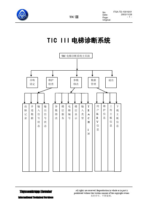
进入TIC电梯诊断系统主页面(图6-2),点击维护检查按钮便可以进入TIC电梯诊断系统维护检查页面(图6-5),然后点击井道数据按钮,进入井道数据页面(图6-7),井道数据页面记录了楼层以及各楼层的脉冲数据. .查看完毕点击返回即可退出井道数据页面
图6-7
进入TIC电梯诊断系统主页面(图6-2),点击维护检查按钮便可以进入TIC电梯诊断系统维护检查页面(图6-5),然后点击输入信号状态按钮,进入输入信号状态页面(图6-8),输入信号状态页面能与电梯主板进行通讯,将主板的信号传输给PDA.查看完毕点击返回即可退出故障记录页面
3.编码器损坏
1.限位开关
2.重新进行井道教入
3.换编码器
05
电梯到站无法开门
1.门锁短接
2.门电机打滑
3.门机不工作
1.停止短接
2.检查皮带
3.检查门机控制器
06
关门受阻时间超过120秒
1.关门时门锁无法合上
2.安全触板动作
3.外呼按钮卡死
4.门电机打滑
5.门机不工作
08
SM-02-B轿厢控制器通讯中断(不接收指令)
故障代码显示
内容
原因
对策
过电流
0C1
加速时
电动机过电流,输出电路相间或对地短路,变频器输出电流瞬时值超过过电流检出值时,过电流保护功能动作
0C2
OC DURING DEC
减速时
0C3
OC AT SET SPD
恒速时
过电压
0U1
OV DURING ACC
加速时
由于电动机再生电流增加,使主电路中间电压超过过电压检测值时,保护功能动作。(200V系列:400Vdc、400系列:800Vdc),但是,变频器输入侧错误地输入过高电压时,不能保护
蒂森控制板操作器说明

D I A G N O S T I C U N I T I Function 01 00 Display of error stack as per: 05.00显示故障堆栈Example:Error Explanation Weighting BW14 03AAjob-specific error messag任务特性故障信息N emergency stop 紧急停梯XX landing 楼层S stopping 停止YY undefined 未定义M spontaneous message 自发信息NN explanations from page 21 解释见21页 B lift blocked 电梯被锁定ZZ N umber of marking flag 标志编号..B o peration phase 运行阶段Significance: Frequency levels of error:含义:故障频繁度Level 1 infrequent 1度不频繁发生Start/Stop buttonLK sensorRun: IS/RS2)UP direction with ISDOWN direction with ISProgram selector wheelLN sensorW/W1 contactorWO/WU SchützSeven-segment-function display flashing1)PulsesCheck-back SR module Safety circuit EKHKTKKT1) can be suppressed with switch 6S1 on circuit board MZ or with switch S5 on circuit board MZ1.1) Dependenton the function involved, reset can either mean emergency stop following by adjusting run or stopping of the lift installation2) Handshake is defined as cyclical data exchange (telegram) between two data carriers.1) SR module can be masked out via teach-in mode function AF 0d. Running-open operation and re-levelling with door open is notpossible.1) Error from TCI work program 03.89/7 – no longer used.2) Error 35 00 and 3b 00 can no longer occur from work program 02.87/4 and error 36 00 can no longer occur from 06.95/25.1) SR module can be masked out through teach-in-mode function AF 0d. N Runnin-open operation and re-levelling with open door notpossible.2) 0C 04 to 0C 0C leads also to stopping, if not provided otherwise in the lift-specific EPROM !1) If errors 65 00 to 74 00 occur more than 3 times, error 4F 00 will follow afterwards, which leads to spontaneous message and stopping1) DSP is the digital signal processor in the CPI controller2) Handshake is defined as cyclical data exchange (telegram) between two data carriers.04 NN TCI control – Interrogation of ZSE solenoid switchesNN is represented as a hexadecimal number; in the event of errors, it indicates the number ofZSE switches (no other than the ZSE switch of the car position may be actuated).04 00 applies to ZSE 25 to ZSE 3104 00 applies to ZSE 17 to ZSE 2404 00 applies to ZSE 9 to ZSE 1604 0C applies to ZSE 1 to ZSE 8Example: 0 4 0 CHexadecimal number 0C??Binary number 0 0 0 0 1 1 0 0????????assigned ZSE switch 8 7 6 5 4 3 2 1The example shows that ZSE switches ZSE3 and ZSE4 (in 3. and 4. landing) have beenactivated. (Also compare hexadecimal code in part 4, page 2)04 NN TCM control – Interrogation of ZSE solenoid switchesIf ZSE switches are closed in the third and fourth landing, the TCM control will file two errors:04 03 und 04 0406 XX TCI control–Door locking not possible (from work program version 08.91/9)The lift will be put out of service for 15 min. after 3 unsuccessful door locking attempts. A newlocking attempt will be initiated after expiry of this period of time.XX = StandortDoor variant – hinged door:A new locking attempt will also be made within these 15 min. after opening of the landing door(TK open) and closingit again (TK closed).Door variant D4 (with mechanical locking device)A start attempt will be enabled within 15 min., as soon as the control receives the bolt contact.06 XX TCM control–Door locking not possibleIf open bolt contact is recognized in the command chain preceding the position the followingerror will follow14 XX (XX = bolt contact main side)18 XX (XX = bolt contact rear side)09 NN Car will be blocked in the landing >4 minExample 0 9 3 1Signal name (LED display on diagnostic unit I row A)0 KKD0 LSD1 KK O.K.1 LS O.K.0 TSUD0 TSOD0 TSU1 TSO activatedFor LEDs and signal names see Operating Instructions of Diagnostic Unit I, function 05 00,column 0d (display of predefined memory locations, from page 25).19 NN Door zone not detectedExample1 VR1 A5A0 TO0 TU1 FL0 FS0 FO0 FUIn the operation phase STOP (lift at standstill), the CPU recognizes that the door zone calculatedfrom the landing vanes was left.For LEDs and signal names see Operating Instructions Diagnostic Unit I function 05 00, column05 (display of predefined memory locations,from page 25)1d NN Emergeny stop (wrong run direction)No run direction or both run directions were produced with the run contactor activated and thebrake disengaged.For LEDs and signal names see Operating Instructions, Diagnostic Unit I, function 05 00, column05 (display of predefined memory locations from page 25).In case of error 1d C8 the processor outputs the signals VR, A5A and FL (but without rundirections); compare above representation of error 19 NN1E NN Deceleration not effectiveBinary display of car positionIt will be examined whether deceleration has been initiated already on reaching the markedterminal landing vanes.The position is indicated by the five bitst 20 to 25 as binary number.Example: 1 E 9 d0 27FO (run direction UP)1 26FU activated (run direction DOWN)0 251 241 23Position (hexadecimal number converted into1 22binary number)0 211 201 E 9d: bits 20 to 27 stand for landing 29, therefore only run direction UP exists, since 26 = 0 and27 = 1, and consequently 9 d will follow.Function 02 00 Display of order number (fromTCI work program version 06.88/6 and with TCM)显示定单号码(从TCI 06.88/6版工作程序起以及TCM梯)Example: Order No.: 27 70 06 42 10?????LED 5 12 3 10 1B A B A B Function 03 00 Position indicator (decimal)楼层显示(十进制)Function 04 00 Operation phase1) Set function 05 00 with program selector wheel2) Press start-stop button3)Select desired column in 7-segment display with program selector wheelExample: Column 0d is desired. For example, select 0C 0d in 7-segment display, then left LED row B applies to column 0C and right LED row A applies to column 0d, etc.4) Interrogate LED display (compare overview and signal description)5) Exit: press start-stop button for longer than 2 s.The LEDs listed in the table will light on selecting the respective column (Col) :1) Error marking1) pulses are counted dependent on the run direction (20 to 27 is displayed in LED row A/B)1) will be displayed as hexadecimal number in LED row A. Example: 09 in LED row A LEDs 0000 1001 light up2)displays last failure before current failure cause column 2C. Is displayed in hexadecimal numbers as in column 2C1) MF3 (VA) stands for circuit board MF3 with double-sided insertion1) MF3 (VA) stands for circuit board MF3 with double-sided insertion1) MF3 (VA) stands for circuit board MF3 with double-sided insertion1) not assigned currently.显示CPI。
蒂森控制板操作器说明
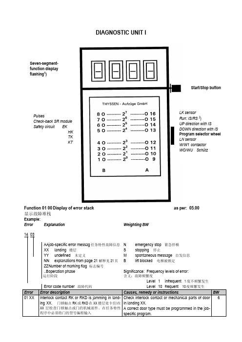
DIAGNOSTIC UNIT IFunction 01 00 Display of error stack as per: 05.00 显示故障堆栈Example:Error Explanation Weighting BW14 03AAjob-specific error messag任务特性故障信息N emergency stop 紧急停梯XX landing 楼层S stopping 停止YY undefined 未定义M spontaneous message 自发信息NN explanations from page 21 解释见21页 B lift blocked 电梯被锁定ZZ N umber of marking flag 标志编号..B o peration phase 运行阶段Significance: Frequency levels of error:含义:故障频繁度Level 1 infrequent 1度不频繁发生Error code number 故障代码Level 10 frequent 10度频繁发生Error Error description Causes, remedy or instructions BW01 XX Interlock contact RK or RKD is jamming in land-ing XX. 门锁触点RK或RKD在XX楼层处卡住/在XX层检查门锁触点或门的机械部件。
在任务特性程序中必须将门的型号编程输入Check interlock contact or mechanical parts of doorin landing XX.A correct door type must be programmed in the job-specific program.6Start/Stop buttonLK sensorRun: IS/RS2)UP direction with ISDOWN direction with ISProgram selector wheelLN sensorW/W1 contactorWO/WU SchützSeven-segment-function display flashing1)PulsesCheck-back SR module Safety circuit EKHKTKKT1) can be suppressed with switch 6S1 on circuit board MZ or with switch S5 on circuit board MZ1.1) Dependenton the function involved, reset can either mean emergency stop following by adjusting run or stopping of the lift installation2) Handshake is defined as cyclical data exchange (telegram) between two data carriers.1) SR module can be masked out via teach-in mode function AF 0d. Running-open operation and re-levelling with door open is not possible.1) Error from TCI work program 03.89/7 – no longer used.2) Error 35 00 and 3b 00 can no longer occur from work program 02.87/4 and error 36 00 can no longer occur from 06.95/25.1) SR module can be masked out through teach-in-mode function AF 0d. N Runnin-open operation and re-levelling with open door not possible.2) 0C 04 to 0C 0C leads also to stopping, if not provided otherwise in the lift-specific EPROM !1) If errors 65 00 to 74 00 occur more than 3 times, error 4F 00 will follow afterwards, which leads to spontaneous message and stopping1) DSP is the digital signal processor in the CPI controller2) Handshake is defined as cyclical data exchange (telegram) between two data carriers.04 NN TCI control – Interrogation of ZSE solenoid switchesNN is represented as a hexadecimal number; in the event of errors, it indicates the number of ZSE switches (no other than the ZSE switch of the car position may be actuated).04 00 applies to ZSE 25 to ZSE 3104 00 applies to ZSE 17 to ZSE 2404 00 applies to ZSE 9 to ZSE 1604 0C applies to ZSE 1 to ZSE 8Example: 0 4 0 CHexadecimal number 0C∣∣Binary number 0 0 0 0 1 1 0 0∣∣∣∣∣∣∣∣assigned ZSE switch 8 7 6 5 4 3 2 1The example shows that ZSE switches ZSE3 and ZSE4 (in 3. and 4. landing) have been activated.(Also compare hexadecimal code in part 4, page 2)04 NN TCM control – Interrogation of ZSE solenoid switchesIf ZSE switches are closed in the third and fourth landing, the TCM control will file two errors: 04 03und 04 0406 XX TCI control–Door locking not possible (from work program version 08.91/9)The lift will be put out of service for 15 min. after 3 unsuccessful door locking attempts. A new lockingattempt will be initiated after expiry of this period of time.XX = StandortDoor variant – hinged door:A new locking attempt will also be made within these 15 min. after opening of the landing door (TKopen) and closingit again (TK closed).Door variant D4 (with mechanical locking device)A start attempt will be enabled within 15 min., as soon as the control receives the bolt contact.06 XX TCM control–Door locking not possibleIf open bolt contact is recognized in the command chain preceding the position the following error willfollow14 XX (XX = bolt contact main side)18 XX (XX = bolt contact rear side)09 NN Car will be blocked in the landing >4 minExample 0 9 3 1Signal name (LED display on diagnostic unit I row A)0 KKD0 LSD1 KK O.K.1 LS O.K.0 TSUD0 TSOD0 TSU1 TSO activatedFor LEDs and signal names see Operating Instructions of Diagnostic Unit I, function 05 00, column0d (display of predefined memory locations, from page 25).19 NN Door zone not detectedExample1 VR1 A5A0 TO0 TU1 FL0 FS0 FO0 FUIn the operation phase STOP (lift at standstill), the CPU recognizes that the door zone calculatedfrom the landing vanes was left.For LEDs and signal names see Operating Instructions Diagnostic Unit I function 05 00, column 05(display of predefined memory locations,from page 25)1d NN Emergeny stop (wrong run direction)No run direction or both run directions were produced with the run contactor activated and the brakedisengaged.For LEDs and signal names see Operating Instructions, Diagnostic Unit I, function 05 00, column 05(display of predefined memory locations from page 25).In case of error 1d C8 the processor outputs the signals VR, A5A and FL (but without run directions);compare above representation of error 19 NN1E NN Deceleration not effectiveBinary display of car positionIt will be examined whether deceleration has been initiated already on reaching the marked terminallanding vanes.The position is indicated by the five bitst 20 to 25 as binary number.Example: 1 E 9 d0 27FO (run direction UP)1 26FU activated (run direction DOWN)0 251 241 23Position (hexadecimal number converted into1 22binary number)0 211 201 E 9d: bits 20 to 27 stand for landing 29, therefore only run direction UP exists, since 26 = 0 and 27 =1, and consequently 9 d will follow.Function 02 00 Display of order number (fromTCI work program version 06.88/6 and with TCM)显示定单号码(从TCI 06.88/6版工作程序起以及TCM梯)Example: Order No.: 27 70 06 42 10∣∣∣∣∣LED 5 12 3 10 1B A B A BFunction 03 00 Position indicator (decimal)楼层显示(十进制)Function 04 00 Operation phase1) Set function 05 00 with program selector wheel2) Press start-stop button3)Select desired column in 7-segment display with program selector wheelExample: Column 0d is desired. For example, select 0C 0d in 7-segment display, then left LED row B applies to column 0C and right LED row A applies to column 0d, etc.4) Interrogate LED display (compare overview and signal description)5) Exit: press start-stop button for longer than 2 s.The LEDs listed in the table will light on selecting the respective column (Col) :1) Error marking1) pulses are counted dependent on the run direction (20 to 27 is displayed in LED row A/B)1) will be displayed as hexadecimal number in LED row A. Example: 09 in LED row A LEDs 0000 1001 light up2)displays last failure before current failure cause column 2C. Is displayed in hexadecimal numbers as in column 2C1) MF3 (VA) stands for circuit board MF3 with double-sided insertion 1) MF3 (VA) stands for circuit board MF3 with double-sided insertion1) MF3 (VA) stands for circuit board MF3 with double-sided insertion1) not assigned currently.显示CPI。
蒂森电梯

蒂森电梯I 型诊断仪7 段数字显示屏起动/停止按键(闪烁 1)旋转脉冲LK 传感器运行:IS/RS 2IS 上行 SR 模块反馈 IS 下行程序选择旋钮安全回路 EKLN 传感器HKTK W/W1 接触器 KTWO/WU 接触器当 I 型诊断仪没有进入 15AF 功能时,LK 和 LN 感应器被井道码板遮挡时,诊断仪上的 LK 和LN 相应的发光二极管闪烁。
当 I 型诊断仪进入 15AF 功能时,LK 和 LN 感应器被井道码板遮 挡时,诊断仪上的 LK 和 LN 相应的发光二极管不闪烁,并且在功能 15AF 里这两个 LED 的配位 也互相对换(见 MA13,类型 6510,顺序号 046)。
用诊断仪 I 总共可查询或处理 16 项功能。
用户可以通过程序选择旋钮选定各项功能。
选 定的功能出现在七段数字显示屏上(闪烁显示)。
使用方法将诊断仪 I 插入相关的印刷电路板(CPU ,门控制,LMS1 等等)。
显示屏显示某项功 能(闪烁)。
用户可调节程序选择旋钮,选择需要的功能。
只有在显示屏闪烁的情况下, 才能从一个功能转换到另一个功能。
退出选定功能:将程序选择旋钮旋转一档,然后按启动/停止键>2 秒。
用户可通过 AF00(dF00,bF00)或者将主开关切断再接通,退出教入功能。
本书中对诊断仪 I 的阐述或功能描述适用于 04.86.3 版起的所有工作程序。
TCI/TCM电 梯控制系统的现行工作程序将在紧急信息栏中公布。
诊断仪 I 的所有功能将在以下章节中分别作详细介绍。
1)当 七 段 显 示 屏 闪 烁 时, 上 图 侧 面 所 示 功 能 将 由 A 列 及 B 列 发 光 二 极 管 指 示 出来。
2)IS ... 检修运行 RS ... 应急电动运行。
诊断仪I(适用于电梯控制系统TCI和TCM)当TCI采用04.86/3版起的工作程序,TCM采用MC,MC1,MC2,MC3控制系统时,以下功能可供选择。
蒂森变频器操作

目录页码1.注意根据设备构成,仅一定(合理的)参数会显示。
例:当选择带有外部运行特征计算机的运行方式时,则不能对内部运行特征计算机的任何参数进行编缉。
2.总述2.1 软件版本此描述包含的软件版本为V2.1,V11.1, V20.4/MO(TMC-板)和V5.1(TMI-板)。
随着产品的进一步研发和改进,我们不定期地对新软件进行更新,界时可能会与此处描述有出入。
软件更新的具体说明请参见SAP中相关技术说明。
我们将以后版本命名如下:对于TMC-板:V2.2, V2.3…或V11.2, V11.3或V20.5/MO, V20.6/MO。
对于TMI-板:V5.2, V5.3。
2.2 同步/异步电机和现代化操作之版本现有4种不同的CPI软件版本,其区别在于不同用途上。
V2.X TMC和V5.X TMI用在同步电机上。
V11.X TMC用在带增量解码器的异步电机上,V20.X/MO TMC用在带或不带增量解码器的第三方电机上。
每个版本都自带一个EPROM。
版本号和技术发布日期印在相关EPROM上。
注:如何调节版本V2.0X/MO TMC将在第6章节作单独描述,因其参数调节程序与其它两种版本有明显不同。
2.3 运行方式版本V2.X TMC, V5.X TMI 和V11.X TMC适用于以下运行方式:TMC 或TMI板,此板能识别哪些额外元件已连接,并能自动拨到正确运行方式。
运行方式“带有CAN总线控制的外部运行特征计算机”不能使用版本V20.X/MO TMC。
-带CAN总线控制的内部运行特征计算机:在变频器中的运行特征计算机-带CAN总线控制的外部运行特征计算机:速度及力矩的参考值由外部运行特征计算机输出,并通过CAN电报传送到变频器中。
-带并联接口TIC的内部运行特征计算机:TIC板有8个数字输入和5个去隅输出。
“变频器通过接口进行控制。
(运行特征计算机在变频器中)此装置构成的标记为CPI....C。
2.4 参数类型参数类型共有4种:-可变参数如:最大速度,转动方向或控制器参数。
- 1、下载文档前请自行甄别文档内容的完整性,平台不提供额外的编辑、内容补充、找答案等附加服务。
- 2、"仅部分预览"的文档,不可在线预览部分如存在完整性等问题,可反馈申请退款(可完整预览的文档不适用该条件!)。
- 3、如文档侵犯您的权益,请联系客服反馈,我们会尽快为您处理(人工客服工作时间:9:00-18:30)。
DIAGNOSTIC UNIT IFunction 01 00 Display of error stack as per: 05.00 显示故障堆栈Example:Error Explanation Weighting BW14 03AAjob-specific error messag任务特性故障信息N emergency stop 紧急停梯XX landing 楼层S stopping 停止YY undefined 未定义M spontaneous message 自发信息NN explanations from page 21 解释见21页 B lift blocked 电梯被锁定ZZ N umber of marking flag 标志编号..B o peration phase 运行阶段Significance: Frequency levels of error: 含义:故障频繁度Error code number 故障代码Level 10 frequent 10度频繁发生Error Error description Causes, remedy or instructions BW01 XX Interlock contact RK or RKD is jamming inlanding XX. 门锁触点RK或RKD在XX楼层处卡住/在XX层检查门锁触点或门的机械部件。
在任务Check interlock contact or mechanical parts of doorin landing XX.A correct door type must be programmed in the job-6Start/Stop buttonLK sensorRun: IS/RS2)UP direction with ISDOWN direction with ISProgram selector wheelLN sensorW/W1 contactorWO/WU SchützSeven-segment-function display flashing1)PulsesCheck-back SR module Safety circuit EKHKTKKT1) can be suppressed with switch 6S1 on circuit board MZ or with switch S5 on circuit board MZ1.1) Dependenton the function involved, reset can either mean emergency stop following by adjusting run or stopping of the lift installation2) Handshake is defined as cyclical data exchange (telegram) between two data carriers.1) SR module can be masked out via teach-in mode function AF 0d. Running-open operation and re-levelling with door open is not possible.1) Error from TCI work program 03.89/7 – no longer used.2) Error 35 00 and 3b 00 can no longer occur from work program 02.87/4 and error 36 00 can no longer occur from 06.95/25.1) SR module can be masked out through teach-in-mode function AF 0d. N Runnin-open operation and re-levelling with open door not possible.2) 0C 04 to 0C 0C leads also to stopping, if not provided otherwise in the lift-specific EPROM !1) If errors 65 00 to 74 00 occur more than 3 times, error 4F 00 will follow afterwards, which leads to spontaneous message and stopping1) DSP is the digital signal processor in the CPI controller2) Handshake is defined as cyclical data exchange (telegram) between two data carriers.04 NN TCI control – Interrogation of ZSE solenoid switchesNN is represented as a hexadecimal number; in the event of errors, it indicates the number of ZSE switches (no other than the ZSE switch of the car position may be actuated).04 00 applies to ZSE 25 to ZSE 3104 00 applies to ZSE 17 to ZSE 2404 00 applies to ZSE 9 to ZSE 1604 0C applies to ZSE 1 to ZSE 8Example: 0 4 0 CHexadecimal number 0C∣∣Binary number 0 0 0 0 1 1 0 0∣∣∣∣∣∣∣∣assigned ZSE switch 8 7 6 5 4 3 2 1The example shows that ZSE switches ZSE3 and ZSE4 (in 3. and 4. landing) have been activated. (Alsocompare hexadecimal code in part 4, page 2)04 NN TCM control – Interrogation of ZSE solenoid switchesIf ZSE switches are closed in the third and fourth landing, the TCM control will file two errors: 04 03 und04 0406 XX TCI control–Door locking not possible (from work program version 08.91/9)The lift will be put out of service for 15 min. after 3 unsuccessful door locking attempts. A new lockingattempt will be initiated after expiry of this period of time.XX = StandortDoor variant – hinged door:A new locking attempt will also be made within these 15 min. after opening of the landing door (TK open)and closingit again (TK closed).Door variant D4 (with mechanical locking device)A start attempt will be enabled within 15 min., as soon as the control receives the bolt contact.06 XX TCM control–Door locking not possibleIf open bolt contact is recognized in the command chain preceding the position the following error willfollow14 XX (XX = bolt contact main side)18 XX (XX = bolt contact rear side)09 NN Car will be blocked in the landing >4 minExample 0 9 3 1Signal name (LED display on diagnostic unit I row A)0 KKD0 LSD1 KK O.K.1 LS O.K.0 TSUD0 TSOD0 TSU1 TSO activatedFor LEDs and signal names see Operating Instructions of Diagnostic Unit I, function 05 00, column 0d(display of predefined memory locations, from page 25).19 NN Door zone not detectedExample1 VR1 A5A0 TO0 TU1 FL0 FS0 FO0 FUIn the operation phase STOP (lift at standstill), the CPU recognizes that the door zone calculated from thelanding vanes was left.For LEDs and signal names see Operating Instructions Diagnostic Unit I function 05 00, column 05(display of predefined memory locations,from page 25)1d NN Emergeny stop (wrong run direction)No run direction or both run directions were produced with the run contactor activated and the brakedisengaged.For LEDs and signal names see Operating Instructions, Diagnostic Unit I, function 05 00, column 05(display of predefined memory locations from page 25).In case of error 1d C8 the processor outputs the signals VR, A5A and FL (but without run directions);compare above representation of error 19 NN1E NN Deceleration not effectiveBinary display of car positionIt will be examined whether deceleration has been initiated already on reaching the marked terminallanding vanes.The position is indicated by the five bitst 20 to 25 as binary number.Example: 1 E 9 d0 27FO (run direction UP)1 26FU activated (run direction DOWN)0 251 241 23Position (hexadecimal number converted into1 22binary number)0 211 201 E 9d: bits 20 to 27 stand for landing 29, therefore only run direction UP exists, since 26 = 0 and 27 = 1,and consequently 9 d will follow.Function 02 00 Display of order number (fromTCI work program version 06.88/6 and with TCM)显示定单号码(从TCI 06.88/6版工作程序起以及TCM梯)Example: Order No.: 27 70 06 42 10∣∣∣∣∣LED 5 12 3 10 1B A B A BFunction 03 00 Position indicator (decimal)楼层显示(十进制)Function 04 00 Operation phase1) Set function 05 00 with program selector wheel2) Press start-stop button3)Select desired column in 7-segment display with program selector wheelExample: Column 0d is desired. For example, select 0C 0d in 7-segment display, then left LED row B applies to column 0C and right LED row A applies to column 0d, etc.4) Interrogate LED display (compare overview and signal description)5) Exit: press start-stop button for longer than 2 s.The LEDs listed in the table will light on selecting the respective column (Col) :1) Error marking1) pulses are counted dependent on the run direction (20 to 27 is displayed in LED row A/B)1) will be displayed as hexadecimal number in LED row A. Example: 09 in LED row A LEDs 0000 1001 light up2) displays last failure before current failure cause column 2C. Is displayed in hexadecimal numbers as in column 2C1) MF3 (VA) stands for circuit board MF3 with double-sided insertion 1) MF3 (VA) stands for circuit board MF3 with double-sided insertion1) MF3 (VA) stands for circuit board MF3 with double-sided insertion1) not assigned currently.显示CPI。