300W恒流恒压电源使用说明书
恒功率中频电源使用说明书

IC3A构成阻抗调节器,它与电流调节器是并列的关系,用于控制逆变桥的引前角。其作用可间接地使恒功率中频电源达到恒功率输出,或者可提高整流桥的运行功率因数。微动开关DIP-2可关掉此调节器。
IC4C构成逆变角调节器,然后由IC4D反相输出。
KGPS-7503φ-380V1200A750V750KW0.5%
KGPS-10003φ-660V920A1200V1000KW0.5%
KGPS-15003φ-660V1380A1200V1500KW0.5%
由CON2-1和CON2-2输入的中频电压信号,经IC1AD转换成方波信号,输入到IC6的30脚。由IC6的15P、16P输出的逆变触发信号,经IC7A隔离放大后,驱动逆变触发MOS晶体管Q5、Q6。IC6B构成逆变压控时钟,输入到IC6的33脚CLOK2;同时又进行频压转换后用于驱动频率表。W6微调电位器用于设定压控时钟的最高频率(即逆变它激信号的最高频率),W5微调电位器用于整定外接频率表的读数。
恒功率中频电源使用说明书
感谢您选用宏润电炉厂最新改进版的KGPS系列恒功率中频电源。为了更好地使用和维护本装置,请在使用前仔细阅读本说明书。
一. 概述
1.
电压PI调节器由IC3B组成,其输出信号由DW1及Q1进行钳位限幅。IC4B和IC5C组成电压闭环自动投入电路。由IC3D构成电流PI调节器,然后由IC4A隔离,控制触发电路的压控时钟。
300W 24V
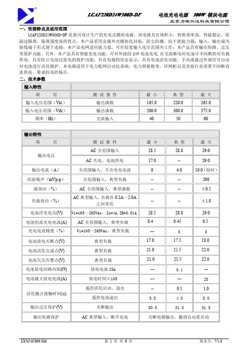
一、性能特点及适用范围LCAF220D24W300D-DF是我司设计生产的充电式模块电源,该电源具有体积小,转换效率高,性能稳定,原副边隔离,隔离强度高的优点;本产品采用金属外壳模块化封装,防尘防潮、抗干扰能力强;输入、输出端为接线端子形式便于连接;本产品电网适应能力强,可在较宽输入电压范围内工作;本产品具有输出短路、过压等保护功能。
另外,本产品具有智能充电功能,可对外接的24V电池充电,在交流断电时电池可不间断的对负载供电,具有防止电池过放电的保护功能;具有电源的状态显示;具有电池活化功能,手动或通过外部信号自动对电池进行活化维护。
本电源适用于电力配网自动化系统,电力智能箱变,环网柜以及其他行业需要不间断直流供电,要求较高的场合。
3.电源内部电路原理图1电源内部原理图图2电源内部隔离图4、面板说明图3电源面板说明1、充电及工作指示灯2、电池放电指示灯3、电池活化指示灯4、电池欠压指示灯5、电源故障(过压)指示灯6、手动活化启动按键7、手动活化退出按键8、手动电池投入按键9、手动电池退出按键1、接线端子5、接线说明5.1接线示意图图4接线示意图接线说明:K1K2K3为用户CPU等控制的继电器触点(触点容量无要求,但不可用光耦代替),R为电池活化放电电阻,负载为用户正常负载,电池为24V电池组。
接线端子容量300V/15A。
具体使用见下面使用说明。
5.2端子定义端子号端子名称定义端子号端子名称定义1ACL交流输入L相12BG遥控电池退出2PE保护接地13RL活化放电负载正3ACN交流输入N相14VG遥控公共接点4NC无电气连接15Vo-负载输出负5VC告警输入正16Vo-负载输出负6POK输入失电告警输出17Vo+负载输出正7HOK电池活化状态输出18Vo+负载输出正8VL电池欠压告警输出19B+电池接入正9VH电源故障告警输出20B+电池接入正10HK遥控活化启动21B-电池接入负11HG遥控活化退出22B-电池接入负6、使用说明6.1电源状态指示充电,绿色,电池充电指示,电池充电时亮,电池放电或电池活化时熄灭;放电,红色,电池放电指示,电池放电时或电池活化时亮,电池充电及电池放电结束时熄灭;活化,黄色,电池活化时亮,否则熄灭;欠压,红色,电池或电源输出欠压时亮,否则熄灭;故障,红色,电源输出过压时亮,否则熄灭。
恒流恒压控制模块使用说明书
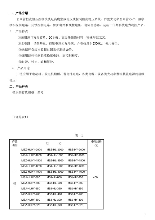
一、产品介绍晶闸管恒流恒压控制模块是高度集成的反馈控制稳流稳压系统,内置大功率晶闸管芯片、数字移相控制电路、反馈控制电路、保护电路和线性电压、电流传感器,是新一代高科技电力调控产品。
⒈产品特点①采用进口方形芯片、DCB板、高级热绝缘材料,特殊焊结工艺。
②主电路、导热基板、控制电路相互隔离,介电强度≥2500V AC,使用安全。
③热循环负载次数超过国家标准近10倍。
④采用线性控制稳流稳压电路,高控制精度。
⑤过流、过热、缺相保护。
⒉产品用途广泛应用于电动机、发电机励磁,蓄电池充电,各类电源,及各类大功率整流装置电源的前级调压。
二、产品种类模块的订货规格、型号:(详见表1)表 11、电流规格为模块正常工作输出最大直流电流平均值或交流电流有效值;电压为模块输入端子间最大输入电压有效值。
2、特殊规格,可按用户要求协议定做。
3、上述表内的型号为常规产品。
当模块需要保护功能时,由用户订货时在模块型号后面加注保护代号。
附:型号义释M xx- xx- xx- x1 2 3 4 5模块订货型号规格共五项,定义如下:第1项:字母M,表示模块。
第2项:模块的类型,定义如下:SZ:三相整流SJ:三相交流DZ:单相整流DJ:单相交流第3项: 模块的功能,定义如下:HL:只有恒流功能HY:只有恒压功能HLHY:具备恒流恒压功能第4项:(2-4)位阿拉伯数字,标记模块的标称电流数。
第5项:模块的保护类别R:过热保护L:过流保护LR:过流过热保护注:对于三相模块,具备过热过流保护时,同时具有缺相保护。
型号示例:MSZ-HLHY-200LR即三相整流200A恒流恒压功能模块,具备过流过热缺相保护功能MSJ-HY-350R即三相交流350A恒压模块,具备过热保护功能注:本册为说明方便,在以下图表中将第3项和第5项省略,以表示各种类型模块。
如:MSZ-350表示350A的恒流、恒压、恒流恒压、有或无保护的各类整流模块。
三模块的使用方法:⒈控制插座引脚功能说明⑪引脚定义1脚:+12V,外接+12V电源正极,工作电流<0.5A。
300W AC DC 电源模块说明书

300W,165-264V AC Input,Dual outputAC/DC battery charging module power supplyRoHSFEATURES●Specially designed for Distribution Automation terminal design,suitable for 220Vdc operating mechanism,and it can charge for capacitor of 50000uF/250V ●Maximum instantaneous power up to 340W●With charging function,the 24V (6-30AH)output Lead-acid battery can be charged,when system connected with battery,it can be used as uninterrupted power supply●Designed in accordance with the power-related requirements of the State Grid Corporation,the main technical indicators meet the relevant industry standards●Battery reverse polarity protection,battery under voltage protection●Output over-current,over-voltage protection ●2.5KVAC high isolation voltage●Industrial grade operating temperature:-40℃to +70℃●Chassis mountingMBP300-2A27D27220is AC/DC battery charge power converter offered by Mornsun.It features wide input voltage range,taking both DC and AC input voltage,output over-current,over-voltage protection,strong ability in adapting power grid.This product has power working status display and Intelligent charging function,it can used to charge the 24V lead-acid battery,when AC is power-off,the battery can supply power to the load;it has battery over discharge protection function,Designed specifically for distribution automation terminal (DTU /FTU).It is widely used in the power industry switch substations,power substation,RMU,Intelligent Package Substation,Intelligent Switch Controller and other industries which need uninterrupted power supply.Selection GuidePart No.Output PowerNominal Output Voltage and Current Maximum Output PowerEfficiency(220VAC,%)(Vo1/Io1)(VB/IB)(Vo2/Io2)MBP300-2A27D2722062.5W27V/1.0A27V/0.5A220V/0.1A340W(No more than 20s,5mins once )80(Io1=1A,Io2=0.1A,disconnect the battery)Input SpecificationsItemOperating Conditions Min.Typ.Max.Unit Input Voltage Range AC input 165220264V AC DC input200310370VDC Input Frequency 475063Hz Input Current 220V AC,Typical load -- 1.0--AHot PlugUnavailableOutput SpecificationsItemOperating Conditions Min.Typ.Max.UnitRated Output CurrentInput voltage range Io1--1--A Io2--0.1--Peak Output Current *Input voltage range Io1(No more than 20s,5mins once,Io2≤0.1A)----6Io2(No more than 20s,5mins once,Io1≤1A)---- 1.36Output Voltage Input voltage range Vo1(Disconnect the battery)--27--VDC Vo2(Adjustable)200220240Line RegulationFull loadVo1--±0.5--%Vo2--±1--Load Regulation0%-100%load Vo1--±1--% Vo2--±5--Ripple&Noise**20MHz bandwidth(peak-to-peak value)(Io1=1A,Io2=0.1A,disconnect the battery)Vo1--200300mVVo2--2000--Floating Charge Voltage Room temperature,Io1=1A,Io2=0AVB--27--VDCBattery Charge Current Room temperature,Io1=1A,Io2=0AIB--0.5--A Battery Discharge Cut-off point Typical load Vo120.52121.5VDC Battery Discharge Cut-off Delay Time Typical load--3--sBattery Reverse Polarity Protection The green and the red lights are turn off,when the battery has been connected.Short Circuit Protection Input voltage range,disconnect the battery Hiccup,Continuous,self-recovery Over-current Protection Input voltage range,disconnect the battery Io1--16--A Over-voltage Protection Input voltage range,disconnect the battery----34VDC Hold-up Time Room temperature,220V AC input,Po=20W--0.3--s Note:*①When the ambient temperature exceeds50℃,Io1and Io2single peak current continuous output time can not exceed15s;②Io1and Io2can not simultaneously output peak current,product peak output power should not be more than340W.(Battery charging power included) **Ripple and noise are measured by“parallel cable”method,please see AC-DC Converter Application Notes for specific operationGeneral SpecificationsItem Operating Conditions Min.Typ.Max.UnitIsolation Voltage Input-outputTest time:1min,leakage current setting value:5mA2500----VAC Input-case2500----Output-case2500----Output-output1500----Impulse Voltage Input-output Apply5kV impulse test voltage between input andoutput.Add1.2/50us impact waveform,includingthree positive impulse and three negative impulsewhose time interval is no less than5seconds.And thereshould not have disruptive discharge during the test.5000----V Input-case5000----Output-case5000----Isolation Resistance Input-output Room temperature50----MΩInput-case Room temperature50----Output-case Room temperature50----Operating Temperature*-40--+70℃Storage Temperature-40--+85Shell Operation temperature*----+80Storage Humidity----95%RH MTBF MIL-HDBK-217F@25℃>100,000hNote:*①When the ambient temperature exceeds50℃,it should be taken the cooling method of force air cooling or post cooling to ensure that the module shield temperature is not more than80℃.②When the ambient temperature is lower than-10℃,the product should be operated with rated load for1mins,before it output340W peak power. Physical SpecificationsCasing Material MetalPackage Dimensions200.00*102.00*45.00mmWeight850g(Typ.)Cooling method Free air convectionEMC SpecificationsEMS ESD IEC/EN61000-4-2Contact ±8KV Perf.Criteria B RS IEC/EN61000-4-330V/m perf.Criteria A EFT IEC/EN61000-4-4±4KV perf.Criteria B Surge IEC/EN61000-4-5line to line±2KV/line to ground±4KV perf.Criteria B CS IEC/EN61000-4-610Vr.m.s perf.Criteria A Voltage dips,short interruptionsand voltage variations immunityIEC/EN61000-4-110%,70%perf.Criteria BPrinciple block diagramFig1.Internal principle diagram Wiring Description1.Wiring diagram2.Terminal DefinitionTerminal No.Terminal name Definition1AC(L)AC input L phase2Protective grounding3AC(N)AC input N phase4-Vo1(B-)Control unit(-)Battery input(-)5B+Battery input(+)6+Vo1Control unit(+)7NC No electrical connection 8+Vo2Operating mechanism(+) 9-Vo2Operating mechanism(-) 10NC No electrical connectionManual Instruction1.Power supply status indicatorCharge,AC input power,green light on,the battery is in charging or floating charging status.Discharge,AC input power off,green light off,red light on,the battery is in discharging status.Reverse,when the input voltage off(or input voltage normal,Vo1and Vo2output normal),but the green and red light are all off,which shows that the battery is polarity reversed.Please check the wiring diagram to re-connect the battery.Input voltage(V AC)Output voltage(VDC)Whether to connectthe batteryLEDPower state Vo1Vo2green light Red light22027220no connect on off Output normal220Batteryvoltage220connect on off Output normal,battery charging000no connect off off No output000connect off on No output,battery access to normal220→0Batteryvoltage220connect on→off off→onOutput normal,battery from charginginto the discharge000connect off off No output,reverse connection ofbattery22027220connect off off Output normal,reverse connection ofbatterye of PowerThe power supply can work when input is AC the alternating current.The power input current to load is powered by power supply, meanwhile charge battery in constant current and voltage.After the battery is charged,power supply to floating charge state automatically,this moment,the power supply float voltage and current to normal self discharge of battery.When AC input voltage off,the battery will continue to power for load,0switch time.When the battery output voltage is lower than the under voltage protection point and last for3-10S,the power supply will turn off automatically.Without AC input,pass external passive nodes make Vo1and B+in short circuit(short circuit time:1-2S,but pin should not be short for a long time,otherwise the battery will lose the protection function.)that can enable the battery to start the output.Vo2output Voltage:200Vdc–240Vdc continuously adjustable,The user can adjust the output voltage to the knob with“output voltage adjustment”.e of BatteryThe power supply can be equipped with24V,6-30AH lead acid battery or colloidal maintenance-free battery,The battery is connected to the battery terminal(B+、B-)of the power supply.We should make sure that the input voltage is off before connect or disconnect the battery.If the red light on after connected the battery,the battery connected normal;if the red light off when connected the battery,the battery polarity connected reverse,please check the wiring diagram to re-connect it.It is forbidden to short-circuit the battery.After connect with the battery,the over-current protection and short-circuit protection of Vo1will be disabled.Simple calculation of battery charging time:Battery capacity C(AH)/Charging current(A)Dimensions and Recommended LayoutAttention Matters in Application(1)Output please use wire that cross area is more than2.5mm²,input terminal should add10A/250V AC Fuse.(2)Please correct connection according to the wiring diagram,do not connect wrongly,AC input terminal is strictly prohibited connected with other terminals wrong,otherwise will cause permanent damage to power.(3)Vo2output peak current can not be long term work.(4)To further reduce the Vo1output ripple noise,the user can in the Vo1output parallel connection with one470–1000uF/50V electrolytic capacitor and1uF multilayer ceramic Capacitor.(5)The output of this product is not allowed to work in parallel.(6)The PE terminal of this product should be reliably connected to the earth,in order to improve the capability of anti-interference.(7)Casing will distribute heat when the power is during operating,in order to ensure the power dissipation is good,please keep a certain gap around the power supply to ensure the air flow smoothly,the temperature sensitive device as far as possible from the power.Note:1.Packing information please refer to Product Packing Information which can be downloaded from .Packing bag number:58220041;2.If the product is not operated within the required load range,the product performance cannot be guaranteed to comply with all parameters in the datasheet;3.Unless otherwise specified,parameters in this datasheet were measured under the conditions of Ta=25℃,humidity<75%with nominal input voltage and rated output load;4.All index testing methods in this datasheet are based on our Company’s corporate standards;5.We can provide product customization service,please contact our technicians directly for specific information;6.Specifications are subject to change without prior notice.Mornsun Guangzhou Science&Technology Co.,Ltd.Address:No.5,Kehui St.1,Kehui Development Center,Science Ave.,Guangzhou Science City,Luogang District,Guangzhou,P.R.China Tel:86-20-38601850-8801Fax:86-20-38601272E-mail:***************。
JT-A-300W-600W电源【数显】使用说明

超声波信号发生器ULTRASONIC GENERATORPOWER-600W使用说明书一.技术参数:1.输出功率:0---600W可选2.输入电压:200---240V AC. 50/60Hz3.工作温度:-20---+65℃4.工作频率:20K---40KHz5.MOS/IGBT最高温度:50度。
二.功能说明:1.功率调节:调节功率电位器,功率可以从零到额定功率可调。
2.电源开关:ON为开启,OFF为关断。
3.显示窗:可显示机器输出功率。
4.电源线:连接机器与市电的连接器件。
注意接地要良好!5.输出接线口:超声清洗机与发生器的连接处。
注意正负极性不可接反。
6.散热风扇:为主功率器件散热。
三.机器接口图示1.面板图功率显示功率调节钮电源开关2.尾部图输出接线端3.内部图数字表头风机架110轴流风机超声输出端电源开关频率计插口调频电位器加厚散热片谐振电感隔离变压器四.机器调试方法:1.调试关键点见下图谐振电感垫气隙处1档2档3档功率抽头线调节频率电位器插数字表头插功率调节电位器插频率计调试步骤:1,把电位器逆时针旋到底,接好测量电流的检测仪(如万用表,电流表,钳形表等),这里要说明下,指针式机箱本身自带电流表,请直接观察电流表。
数显机箱请自行接好电流检测仪。
2,把电感上垫在中间的黄色薄片全部拿掉或留左右各一片,两边去留多少一定要尽量对称平衡。
提示:可以使用任何绝缘材质的薄片代替。
前提是不容易变形吸水。
3,插上频率计。
提示:可以使用带测频率功能的万用表测量,但是没有频率计安全和方便。
而且用万用表测量时,电位器必须逆时针旋到底。
4,接通电源。
5,根据振子的频率,调节蓝色电位器,观察频率计上的频率变化,调至到振子的频率6,电位器逆时针旋到底,关闭电源7,把换能器的正负极接至线路板输出端,贴有白底黑字标签处。
8,打开电源,旋钮电位器顺时针方向拧到头9,边观察电流,边拉起电感的磁芯,当电流达到最大或者适当的值,记下磁芯间的间隙。
480V 300W LED 电源设计指南说明书

LCC 拓扑:在 480V/300W AC-DC LED 电源中实现高效率作者:Akshat Jain,Fabrizio Di Franco,意法半导体近年来,谐振转换器变得越来越流行,并广泛应用于各种应用,包括服务器通信和电源、照明和消费电子产品等。
谐振转换器之所以具有吸引力,部分原因在于它可以轻松实现高效率。
它还允许高频操作。
本设计说明介绍了意法半导体的 STEVAL–LLL009V1 演示板:一种在 300W 数字电源中实现谐振转换的方法(见图 1)。
该系统由功率因数校正 (PFC) 和隔离式 DC-DC 转换器级(半桥 LCC 谐振转换器)组成,具有同步整流功能。
DC-DC 功率级和输出同步整流使用意法半导体的 STM32F334 微控制器进行数字控制,而在转换模式下运行的 PFC 级基于意法半导体的 L6562AT PFC 控制器。
该参考设计可以在恒压 (CV) 或恒流 (CC) 模式下工作。
演示设计的性能已在交流电源条件下、在整个负载范围内、270V-480V 交流输入电压范围内进行了评估。
电能质量参数在谐波标准 IEC 61000-3-2 的可接受范围内。
数字控制的优点该设计采用数字控制方案,而不是基于使用模拟 IC 的标准方法。
数字控制的主要优点是编程灵活性,使设计人员能够针对任何给定条件即时调整参数和工作点,而无需对硬件进行任何修改。
相比之下,模拟系统只能针对特定范围进行调谐。
此外,用于照明电源的有价值的功能往往更具成本效益,并且更容易集成到数字系统中,因为它们可以由单个 IC 实现。
例如:●模拟或数字调光●可通过0-10V、无线或其他方案进行调光控制●调光分辨率配置●温度监测●保护功能●通信功能此外,数字控制在嘈杂的条件下比模拟方法提供更高的稳定性,因为它对组件容差、温度变化和电压漂移不太敏感。
图1:STEVAL-LLL009V1评估套件系统概览STEVAL-LLL009V1 参考设计(见图 2)将 270V-480V AC 范围内的电源输入电压转换为 48V DC,CV 模式下的最大电流为 6.25A。
恒压恒流数控电源使用说明说明书
恒压恒流数控电源使用说明Constant Voltage and Constant CurrentDCPower Supply Instruction型号: RD6006/ RD6006-W/ RD6006P/ RD6006P-W /RD6024/ RD6024-WModel: RD6024/R26024-W修订时间:2022.3.7Date: 2022.1.7Constant Voltage and Constant CurrentDC Power Supply InstructionModel: RD6024/RD6024-WDate: 2022.1.7 Dear users, thank you for purchasing the constant voltage constant current DC power supply produced by Hangzhou Ruideng Technology Co., Ltd. In order to let you know more about the full function of this product, get a better experience and avoid misuse. Please read this instruction carefully before using it. Keep it for future reference.Note: This instruction is corresponding to firmware V1.36, the page and operation may be different under different firmware versions, please pay attention when using it. We do recommend you to download the latest firmware for better experience.CONSTANT VOLTAGE AND CONSTANT CURRENT (38)DC POWER SUPPLY INSTRUCTION (38)1.1T ECHNICAL P ARAMETER (41)1.2C ORE F UNCTION (42)1.3P ANEL I NSTRUCTION (43)1.3.1 Front Panel (43)1.3.2 Back Panel (44)1.4O PERATION I NSTRUCTION (45)1.4.1 Main Page (45)1.4.2 Operation Introduction (47)ANDROID APP INSTRUCTION (54)2.1M OBILE P HONE APP I NSTALLATION (54)2.1.1 APP Download (54)2.2I NSTALLATION I NTRODUCTION (54)2.2.1 APP Update (54)2.2.2 APP Interface Display (54)2.2.3 APP Operation (55)IOS APP INSTRUCTION (59)3.1M OBILE P HONE APP I NSTALLATION (59)3.1.1 APP Download (59)3.2I NSTALLATION AND O PERATION (59)3.2.1 APP Update (60)3.2.2 UI Instruction (60)3.2.3 APP Operation (61)PC SOFTWARE INSTALLATION AND OPERATION INSTRUCTION (64)4.1S OFTWARE D OWNLOAD (64)4.1.1 Unzip Files (64)4.1.2 Unzip Files (64)4.2S OFTWARE O PERATION (65)4.2.1 Software Connection (65)4.2.2 PC Software Operation Instruction (66)4.3F UNCTIONS I NTRODUCTION (66)4.3.1 Basic Functions (67)4.3.2 Calibration (68)4.3.3 Advanced Function (69)4.3.4 RS485 Multiple Devices Communication (69)4.3.5 Firmware Update (70)4.3.6 Boot Logo Update (71)4.3.7 Version Update Detection (72)4.3.8 Language Setting (73)4.3.9 About (73)APPENDIX (75)A PPENDIX 1:C OMMON B ATTERY V OLTAGE C OMPARISON T ABLE (75)A PPENDIX 2:C OMMON E LECTRIC C AR/B IKE B ATTERY V OLTAGE C OMPARISON C HART (76)1.1 Technical ParameterModel RD6024 RD6024-W Input voltage range 6-70.00VOutput voltage range 0-60.00VOutput current range 0-24.00AOutput power range 0-1440WInput voltage measurement resolution 0.01VOutput voltage setting measurement resolution 0.01VOutput current setting measurement resolution 0.01ABattery voltage measurement resolution 0.01VInput voltage measurement accuracy ±(1%+5 digits)Output voltage accuracy between setting andmeasurement±(0.3%+3 digits)Output current accuracy between setting andmeasurement±(0.5%+5 digits)Battery voltage measurement accuracy ±(0.5%+3 digits) Automatic cut off current value when charging Set by yourself(higher than 100mA) Output ripple typical 100mV@12A,150mV@24A VPP①Working temperature range -10℃~40℃External sensor Temperature detection range: -10℃~100℃/0℉~200℉External sensor Temperature detection accuracy: ±3℃/±6℉Constant voltage mode response time 2ms(0.1A-5A load)Constant voltage mode load regulation ±(0.1%+2 digits)Constant current mode load regulation ±(0.1%+3 digits)Capacity measurement range 0-9999.99AhEnergy measurement range 0-9999.99WhConstant voltage mode response time ±2%Max output voltage (input voltage÷1.1)-1②Cooling fan start conditionOutput current>8A or System temperature>45℃Cooling fan shut down condition when working Output current <7.9A and System temperature <45℃Over temperature protection System temperature >80℃Screen brightness setting 0-5(6 level in total)Screen 2.4 inch color HD displayWeight(with package) About 0.72KgProduct dimension 167*81*69mmSupport USB communication YesSupport WiFi communication No Yes①:Ripple measurement method: noise and ripple are measured at X1 range, AC coupling,20 MHz of bandwidth on your oscilloscope with a 0.1uF parallel capacitor at the output terminals②for example: input voltage is 24V,the max output voltage is 20.8V。
恒流电源入门
恒流电源入门今天我们将一起学习什么是恒流电源?以及如何用一个恒流电源驱动 LED 和激光二极管。
学习本教程之前最好先学习我之前的线性稳压器入门教程。
各种稳压器在电子硬件这个行当里,大多数时间,你会同恒压电源打交道。
电压适配器、线性稳压器和其他类型的电源可能有很小的纹波,但它们基本上是恒压电源。
那么什么是恒流电源呢?顾名思义,它是一种无论负载如何变化都会输出恒定电流的电路。
恒流电源对于一个理想的 1 安培恒流源,无论是将其连接到 1 欧姆电阻或100 欧姆电阻,它总是会提供 1 安培的电流通过电阻。
总是输出1 安培不想使用电阻?在电路中放置一个 LED,无论 LED 是什么颜色,它都会对 LED 输出恒定的电流。
某些器件,如大功率LED,最好给它们提供恒定电流,因为它们需要维持相同的亮度。
大功率 LED 灯可以用恒流源来驱动一串 LED, 这里我搭建了一个 12 mA 的恒流源,不管串联多少个LED ,它们的电流都是 12 mA。
串多串少一个样那么我们如何构建它呢?好吧,构建恒流源的最简单方法是使用LM317。
LM317下面是电路图:恒流电源电路电路很简单。
将电源连接到芯片的输入引脚,然后在输出和调整(ADJ)引脚之间并联一个电阻。
一对10 微法的电容有助于在负载突然变化的时候稳定电流。
电阻 R 的值决定了恒定电流是多少。
比如,如果使用 100 欧姆的电阻,它会让电路输出 12.5 毫安的理论电流值:1.25 V / 100 欧姆 = 12.5 毫安。
现在让我们用万用表量一量输出电流。
当接一个LED 时,输出电流为 12.6 毫安:一个 LED再串联上一个 LED, 电流还是 12.6 毫安:两个 LED我们还可以再串上一个激光二极管,电流还是 12.6 毫安:再串一个激光二极管无论负载如何变化,电流都保持不变。
另一个很酷的事情是,即使输入电压从 12 伏增加到 24 伏,电流也保持不变。
尽管如此,输入电压仍然很重要。
恒压恒流数控电源DPS3003 DPS3005使用说明说明书
恒压恒流数控电源使用说明适用型号:DPS3003/DPS3005/DPS5005/DPS8005修订时间2021-9-1尊敬的用户,感谢您购买由杭州睿登科技有限公司出品的恒压恒流数控电源,为了让您更快了解本产品的全部功能,获得更好的使用体验,避免出现误操作,使用前请仔细阅读本说明,并保留好以便日后查阅(请注意本说明书中红字提醒的事项)。
1.1产品简介本产品是集模拟调整和数字控制于一身,体积小巧,功能强大,是众多爱好者及实验室工作者的首选。
产品带有预设存储功能,可存储10组预设值,并可快捷调出两组预设值。
自带液晶显示,通过液晶屏可方便查看设定电压、设定电流、输出电压、输出电流、输出功率、输入电压等。
主界面右侧区域可以方便地看出当前输出开关状态、恒压/恒流状态、输出异常状态、按键锁定状态以及预设值序号。
在数据设定界面中还可以对过压值、过流值、过功率值、预设值、液晶亮度以及是否开机输出等进行设置调整。
本产品分为非通信版、USB通信版、蓝牙通信版;通信版本可以连接PC,蓝牙版本可以连接安卓手机(DPS3003仅有非通信版)。
本产品体积小巧、功能先进、可视效果好、可操作性强、精度高,既可独立使用,也可嵌入设备中,应用范围广。
1.2系列产品参数1.3接线说明产品是DC-DC降压输出,须保证输入电压是输出电压的1.1倍以上,自然散热条件下可以满负荷输出,装在机壳内请加装散热风扇。
90V为极限输入电压,请一定留余地使用,必须直流输入,不可使用交流甚至使用220V供电,给电池充电时不要接反,错误操作将导致产品烧坏。
请严格按照上述接线说明和注意事项使用。
超过极限电压,使用交流作为输入,接线错误以及给电池充电接反都会造成模块损坏,有些损坏为不可逆,请务必注意。
1.4面板说明A:电压设置/向上选择/M1数据快捷调出B:数据设置/调出预设值C:电流设置/向下选择/M2数据快捷调出D:1.44寸彩色液晶显示屏E:编码电位器:数据调整/切换位置/解锁&锁定按键F:输出开关1.5 显示界面说明G:输出电压设定值L:输出电流设定值H:输出电压检测值M: 按键状态指示I:输出电流检测值N: 异常状态指示J:输出功率检测值O:恒压/恒流状态指示K:输入电压检测值P: 当前预设值序号Q: 输出开关状态指示R:输出电压设定V:过功率保护值设定S:输出电流设定W:屏幕背光亮度设定T:过压保护值设定X:预设值参数设定U:过流保护值设定Y:当前输出电压、电流检测值1.6操作说明上电后欢迎界面显示产品型号和软件版本号,然后进入主界面。
SST-TX300TFX系列T型形式电源供电器产品说明书
SPECIFICATION TFX Form FactorSST-TX300300W Switching Power Supply With Active PFC80Plus Bronze011.1 VOLTAGE1.2 FREQUENCY47Hz ~ 63Hz1.3 CURRENT115/230Vac 6.3A max.1.4 INRUSH CURRENT100A max. when AC input 230Vac at 25 cold start.1.0 INPUT:MINIMUM NOMINAL MAXIMUM UNITS90 100~240 264 Vrms1.5 POWER EFFICIENCYMEET 80 Plus Bronze at 115/230Vac input.1.6 LEAKAGE CURRENT3.5mA max.1.7 POWER FACTORPF > 0.90 (full load). 1.8 ErP REQUIREMENTThe continuous total output power is 300W max The combined power of +5V and +3.3V is 95W max. The combined power of +12V1 and +12V2 is 276W max.Peak currents may last up to 10 seconds with not more than one occurrence per minute.A 0.1uF ceramic disk capacitor and a 10Uf electrolytic capacitors to simulate system loading. The oscilloscope bandwidth is set at 20 MHz coaxial probe will be used to measure it.Meet ErP 2013 requirement02.LOAD 5V3.3V +12V -12V +5VSB SPEC20% 1.83A 1.72A 3.59A 0.05A 0.31A 82% 50% 4.58A 4.29 A 10.77A 0.12A 0.78A 85% 100% 9.16A 8.58A 17.74A 0.23A 1.56A 82%2.0 OUTPUT:Voltage+5V +3.3V +12V1 +12V2 -12V +5Vsb *① *① Max load16.0A 15.0A 14.0A 15.0A 0.3A2.0AMin load 0.5A 0.3A 0.5A 0.5A 0.0A 0.0A Peak load / 21.0A 16.0A 18.0A / 3.0A * Regulation +5,-5% +5,-5% +5,-5% +5,-5% +10,-10% +5,-5% *② *② Ripple & Noise50mV 50mV 120mV 120mV 120mV 50mV03LOAD REGULATION TEST TABLE:2.1 REMOTE ON/OFFModelThe cross regulation defined as follows , the output regulation should be within the specified range.TTL High/PS-OFF; TTL Low/PS-ONVIL=0.8Vmax, IIL=-1.6mAmax @Vin=0.4VVIH=2.0Vmin @Iin=-200uA, VIH=5.25Vmax @open ckt.2.2 HOLD-UP TIME16m sec (minimum) at 60% of full load at 230Vac input.2.3 POWER GOOD DELAY 100-500 msec.2000 msec max.At Nominal Line Full Load.DC output transient step sizes as below table:2.4 POWER FAIL DELAY 2.5 TURN-ON DELAY TIME2.6 TRANSIENT OVERSHOOT1 msec.*Voltage +3.3V +5V +12V1 +12V2 -12V +5Vsb300WLOAD1 0.3A 0.5A 0.5A 0.5A 0A 0ALOAD2 6.0A 6.5A 5.5A 4.5A 0.15A 1.0A LOAD310.0A 13.0A 8.6A 7.0A 0.3A 2.0A LOAD4 3.0A 16.0A 8.2A 8.2A 0.3A 2.0A LOAD5 15.0A 9.44A 7.5A 8.0A 0.3A 2.0A LOAD6 1.0A 5.8A 11.0A 11.0A 0.1A 0.5AOutput voltage +5V +3.3V +12VMax. step size 30% 30% 40%Load-changing repetition rate of 10m seconds.Load slew rated 1.0A/uS and capacitive load as below :+5V +3.3V +12V -12V +5Vsb6000uF 6000uF 6000uF 350uF 350uF2.7 RISE TIME20ms max at full load.3.0 PROTECTION:When OPP, OVP or short protection is triggered, the main outputs will be latched off.The main outputs can be reset by cycling the DC remote on/off or AC power. +5Vsb output is auto recovery when fault condition removed.3.1 OVER POWER PROTECTIONFoldback at 360~480W3.2 OVER VOLTAGE PROTECTION+3.3V output 4.5 Vmax.+5.0V output 7.0 Vmax.+12.0V output 15.6 Vmax.3.3 SHORT PROTECTIONAll output to GND.044.0 ENVIRONMENT:WATT100% full load80% full loadTEMP 0deg10deg20deg30deg40deg50deg4.1 OPERATING TEMP. 0 to +404.2 STORAGE TEMP. -20 to +704.3 OPERATING HUMIDITY 20% to 90%,non-condensing4.4 STORAGE HUMIDITY 5% to 95%, non-condensing4.5 OPERATING ALTITUDE 0 to 10,000 feet4.6 STORAGE ALTITUDE 0 to 50,000 feet5.0 HI-POT:(Input/Output isolation)5.1 PRIMARY TO SECONDARY1800Vac for 1 minute5.2 INSULATION RESISTANCEPrimary to earth ground 500Vdc , 50M ohms Min.056.0 CE REQUIREMENTS6.1 CONDUCTED EMI1. MEET FCC Class B2. MEET CISPR 22 Class B6.2 SAFETY STANDARDS1. MEET CUL (UL 60950)2. MEET TUV( EN60950)3. MEET CB (IEC 950 )4. MEET CE5. MEET CCC6.3 HARMONIC1. MEET IEC61000-3-2,Class D7.0 MTBF at 25 (demonstrated)100K hrs minimum8.0 DIMENSIONSLxWxH=175 mm x 85 mm x 65 mm06。