外文翻译英文
外文翻译 - 英文

The smart gridSmart grid is the grid intelligent (electric power), also known as the "grid" 2.0, it is based on the integration, high-speed bidirectional communication network, on the basis of through the use of advanced sensor and measuring technology, advanced equipme nt technology, the advancedcontrol method, and the application of advanced technology of decision support system, realize the power grid reliability, security, economic, efficient, environmental friendly and use the security target, its main features include self-healing, incentives and include user, against attacks, provide meet user requirements of power quality in the 21st century, allow all sorts of different power generation in the form of access, start the electric power market and asset optimizatio n run efficiently.The U.S. department of energy (doe) "the Grid of 2030" : a fully automated power transmission network, able to monitor and control each user and power Grid nodes, guarantee from power plants to end users among all the nodes in the whole process of transmission and distribution of information and energy bi-directional flow.China iot alliance between colleges: smart grid is made up of many parts, can be divided into:intelligent substation, intelligent power distribution network, intelli gent watt-hourmeter,intelligent interactive terminals, intelligent scheduling, smart appliances, intelligent building electricity, smart city power grid, smart power generation system, the new type of energy storage system.Now a part of it to do a simple i ntroduction. European technology BBS: an integration of all users connected to the power grid all the behavior of the power transmission network, to provide sustained and effective economic and security of power.Chinese academy of sciences, institute of electrical: smart grid is including all kinds of power generation equipment, power transmission and distribution network, power equipment and storage equipment, on the basis of the physical power grid will be modern advanced sensor measurement technology, network technology, communicationtechnology, computing technology, automationand intelligent control technology and physical grid highly integrated to form a new type of power grid, it can realize the observable (all the state of the equipment can monitor grid), can be controlled (able to control the power grid all the state of the equipment), fully automated (adaptive and self-healing) and system integrated optimization balance (power generation, transmission and distribution, and the optimization of the balance between electricity), so that the power system is more clean, efficient, safe and reliable.American electric power research institute: IntelliGrid is a composed of numerous automation system of power transmission and distribution power system, in a coordinated, effective and reliable way to achieve all of the power grid operation: have self-healing function;Rapid response to the electric power market and enterprise business requirements;Intelligent communication architecture, realizes the real-time, security, and flexible information flow, to provide users with reliable, economic power services. State grid electric power research institute, China: on the basis of the physical power grid (China's smart grid is based on high voltage network backbone network frame, different grid voltage level based on the coordinated development of strong power grid), the modern advanced sensor measurement technology, communication technology, information technology, computer technology and control technology and the physical power grid highly integrated to form a new type of power grid.It to fully meet user demand for electricity and optimize the allocation of resources, guarantee the safety, reliability and economy of power supply, meet environmental constraints, ens ure the quality of electric energy, to adapt to the development of power market, for the purpose of implementing the user reliable, economic, clean and interactive power supply and value-added services.BackgroundStrong smart grid development in the wor ld is still in its infancy, without a common precisely defined, its technology can be roughly divided into four areas: advanced Measurement system, advanced distribution operation, advanced transmission operation and advanced asset management.Advanced meas urement system main function is authorized to the user, make the system to establish a connection with load, enabling users to support the operationof the power grid;Advanced core distribution operation is an online real-time decision command, goal is to disaster prevention and control, realizing large cascading failure prevention;Advanced transmission operation main role is to emphasize congestion ma nagement and reduce the risk of the large-scale railway;Advanced asset management is installed in the system can provide the system parameters and equipments (assets) "health" condition of advanced sensor, and thereal-time information collected by integrat ion and resource management, modeling and simulation process, improve the operation and efficiency of power grid.The smart grid is an important application of Internet of things, and published in the journal of computer smart grid information system archit ecture research is carried on the detailed discussion on this, and the architecture of the smart grid information system are analyzed.The market shareThe establishment of the smart grid is a huge historical works.At present many complicated smart grid project is underway, but the gap is still great.For the provider of the smart grid technology, promote the development of facing the challenges of the distribution network system i s upgrading, automation and power distribution substation transportation, smart grid network and intelligent instruments.According to the latest report of parker investigators, smart grid technology market will increase from $2012 in 33 billion to $2020 in 73 billion, eight years, the market accumulated up to $494 billion.China smart grid industry market foresight and investment forward-looking strategic planning analysis, points out that in our country will be built during the "twelfth five-year""three vertical and three horizontal and one ring" of uhv ac lines, and 11 back to u hv dc transmission project construction, investment of 300 billion yuan.Although during the period of "much starker choices-and graver consequences-in" investment slowed slightly, the investment is 250 billion yuan.By 2015, a wide range of national power grid, long distance transmission capacity will reach 250 million kilowatts, power transmission of 1.15 trillion KWH per year, to support the new 145 million kilowatts of clean energy generation given and sent out, can satisfy the demand of morethan 1 million electric cars, a grid resource configuration optimization ability, economic efficiency, safety and intelligent levels will be fully promoted.The abroad application of analysisIn terms of power grid development foundation, national electricity dema nd tends to be saturated, the grid after years of rapid development, architecture tends to be stable, mature, have a more abundant supply of electric power transmission and distribution capacity.Germany has "E - Energy plan, a total investment of 140 million euros, from 2009 to 2012, four years, six sites across the country to the smart grid demonstration experiment.At the same time also for wind power and electric car empirical experiments, testing and management of power consumption of the Internet.Big companies such as Germany's Siemens, SAP and Swiss ABB are involved in this plan.To smart grid Siemens 2014 annual market scale will reach 30 billion euros, and plans to take a 20% market share, make sure order for 6 billion euros a year.The advanced nat ureCompared with the existing grid, smart grid, reflects the power flow, information flow and business flow marked characteristics of highly integration, its advancement and advantage mainly displays in:(1) has a strong foundation of grid system and te chnical support system, able to withstand all kinds of external disturbance and attacks, can adapt to large-scale clean energy and renewable energy access, strong sex of grid reinforced and ascend.(2) the information technology, sensor technology, automatic control technology organic combination with power grid infrastructure, a panoramic view of available power grid information, timely detection, foresee the possibility of failure.Fault occurs, the grid can be quickly isolate fault,realize self recovery,to avoid the occurrence of blackouts.(3) flexible ac/dc transmission, mesh factory coordination, intelligent scheduling, power storage, and distribution automation technology widespread application, makes the control of power grid operation more flexibl e,economic, and can adapt to a large number of distributed power supply, power grid and electric vehicle charging and discharging facility access.(4) communication, information, and the integrated use of modern management technology, will greatly improve the efficiency of power equipment, and reduce the loss of electrical power, making the operation of power grid is more economic and efficient.(5) the height of the real-time and non real-time information integration, sharing and utilization, to run the show management comprehensive, complete and fine grid operation state diagram, at the same time can provide decision support, control scheme and the corresponding response plans.(6) to establish a two-way interactive service mode, users can real-time understand the status of the power supply ability, power quality, price and power outage information, reasonable arrangement of electric equipment use;The electric power enterprise can obtain the user's electricity information in detail, to provide more value-added services.developmentaltrend"Twelfth five-year" period, the state grid will invest 500 billion yuan to build the connection of large ene rgy base and center of the "three horizontal three longitudinal" main load of ultra high voltage backbone network frame and 13 back to long branch, engineering, to form the core of the world first-class strong smart grid."Strong smart grid technology standards promulgated by the state grid system planning", has been clear about the strong smart grid technology standards roadmap, is the world's first used to guide the development of smart grid technology guiding standards.SGC planning is to built 2015 basic information, automation, interaction characteristics of strong smart grid, formed in north China, central China, east China, for the end to the northwest and northeast power grid for sending the three synchronous power grid, the grid resource allocati on ability, economic efficiency and safety level, technology level and improve intelligent level.(1) the smart grid is the inevitable developing trend ofpower grid technology.Such as communication, computer, automation technology has extensive applicati on in the power grid, and organic combination with traditional electric power technology, and greatly improve the intelligent level of the power grid.Sensor technology and information technology application in the power grid, the system state analysis and auxiliary decision provides the technical support, make it possible to grid self-healing.Scheduling technology, automation technology and the mature development of flexible transmission technology, for the development and utilization of renewable energy an d distributed power supply provides the basic guarantee.The improvement of the communication network and the popularization and application of user information collection technology, promote the two-way interaction with users of the grid.With the further development of various new technologies, application and highly integrated with the physical power grid, smart grid arises at the historic moment.(2) the development of smart grid is the inevitable choice of social and economic development.In order to ach ieve the development of clean energy, transport and given power grid must increase its flexibility and compatibility.To withstand the increasingly frequent natural disasters and interference, intelligent power grid must rely on means to improve its securit y defense andself-healing ability.In order to reduce operating costs, promote energy conservation and emissions reduction, power grid operation must be more economic and efficient, at the same time must to intelligent control of electric equipment, reduce electricity consumption as much as possible.Distributed generation and energy storage technology and the rapid development of electric cars, has changed the traditional mode of power supply, led power flow, information flow, business flow constantly fusion, in order to satisfy the demands of increasingly diverse users.PlanJapan plans to all the popularity of smart grid in 2030, officer of the people at the same time to promote the construction of overseas integrated smart grid.In the field of battery, Japanese firms' global market share goal is to strive to reach 50%, with about 10 trillion yen in the market.Japan's trade ministry has set up a "about the next generation of energy systems international standardizationresearch institute", the japan-american established in Okinawa and Hawaii for smart grid experimental project [6].Learns in the itu, in 2020 China will be built in high power grid with north China, east China, China as the center, northeast, northwest 750 kv uhv power grid as the sending, connecting each big coal base, large hydropower bases, big base for nuclear power, renewable energy base, the coordinated development of various grid strong smart grid.In north China, east China, China high voltage synchronous ZhuWangJia six "five longitudi nal and transverse" grid formation.The direction ofIn the green energy saving consciousness, driven by the smart grid to become the world's countries to develop a focus areas.The smart grid is the electric power network, is a self-healing, let consum ers to actively participate in, can recover from attacks and natural disasters in time, to accommodate all power generation and energy storage, can accept the new product, service and market, optimize asset utilization and operation efficiency, provide qua lity of power supply for digital economy.Smart grid based on integrated, high-speed bidirectional communication network foundation, aims to use advanced sensor and measuring technology, advanced equipment, technology and advanced control methods, and adv anced technology of decision support system, realize the power grid reliability, security, economic, efficient, environmental friendly, and the use of safe run efficiently.Its development is a gradual progressive evolution, is a radical change, is the product of the coordinated development of new and existing technologies, in ad dition to the network and smart meters also included the wider range.Grid construction in high voltage network backbone network frame, all levels of the coordinated development, informatization, automation, interaction into the characteristics of strong smart grid, improve network security, economy, adaptability and interactivity, strength is the foundation, intelligence is the key.meaningIts significance is embodied in the foll owing aspects:(1) has the strong ability of resources optimization allocation.After the completion of the smart grid in China, will implement the big water and electricity, coal, nuclear power, large-scale renewable energy across regions, long distance, large capacity, low loss, high efficiency, regional power exchange capacity improved significantly.(2) have a higher level of safe and stable operation.Grid stability and power supply reliability will be improved, the safety of the power grid close coord ination between all levels of line, have theability to against sudden events and serious fault, can effectively avoid the happening of a wide range of chain failure, improve power supply reliability, reduce the power loss.(3) to adapt and promote the dev elopment of clean energy.Grid will have wind turbines power prediction and dynamic modeling, low voltage across, and active reactive power control and regular units quickly adjust control mechanism, combined with the application of large capacity storage technology, the operation control of the clean energy interconnection capacity will significantly increased, and make clean energy the more economical, efficient and reliable way of energy supply.(4)implementing highly intelligent power grid scheduling.Co mpleted vertical integration, horizontal well versed in the smart grid scheduling technology support system, realize the grid online intelligent analysis, early warning and decision-making, and all kinds of new transmission technology and equipment of effi cient control and lean control of ac/dc hybrid power grid.(5)can satisfy the demands of electric cars and other new type electric power user services.Would be a perfect electric vehicle charging and discharging supporting infrastructure network, can meet the needs of the development of the electric car industry, to meet the needs of users, realize high interaction of electric vehicles and power grid.(6) realize high utilization and whole grid assets life cycle management.Can realize electric grid system of the whole life cycle management plan.Through smart grid scheduling and demand side management, power grid assets utilization hours, power grid assets efficiency improvedsignificantly.(7) to realize power convenient interaction between the user and the grid.Will form a smart electricity interactive platform, improving the demand side management, to provide users with high-quality electric power service.At the same time, the comprehensive utilization of the grid can be distributed power supply, intelli gent watt-hour meter, time-sharing electricity price policy and the electric vehicle charging and discharging mechanism, effectively balance electric load, reduce the peak valley load difference, reduce the power grid and power construction costs.(8)grid management informatization and the lean.Covering power grid will each link of communication network system, realize the power grid operation maintenance integrated regulation, data management, information grid spatial information services, and production and scheduling application integration, and other functions, to realize all-sided management informatization and the lean.(9) grid infrastructure of value-added service potential into full play.In power at the same time, the national strategy of "triple play" of services, to provide users with community advertising, network television, voice and other integrated services, such as water supply, heating, gas industry informatization, interactive platform support, expand the range of value-added services and improve the grid infrastructure and capacity, vigorously promote the development of smart city.(10)Gridto promote the rapid development of related industries.Electric power industry belongsto the capital-intensive and technology-intensive industry, has the characteristics of huge investment, long industrial chain.Construction of smart grid, which is beneficial to promote equipment manufacturing information and communication industry technology upgrade, for our country to occupy the high ground to lay the foundation in the field of electric power equipment manufacturing.Important significanceLife is convenientThe construction of strong smart grid, will promote the development of intelligent community, smart city, improve people's quality of life.(1) to make life more convenient.Home intelligent power system can not onlyrealize the real-time control of intelligent home appliances such as air conditioning, water heater and remote control;And can provide telecommunication network, Internet, radio and television network access services;Through intelligent watt-hour meter will also be able to achieve au tomatic meter reading and automatic transfer fee, and other functions.(2) to make life more low carbon.Smart grid can access to the small family unit such as wind power and photovoltaic roof, pushing forward the large-scale application of electric cars, so as to raise the proportion of clean energy consumption, reduce the pollution of the city.(3) to make life more economical.The smart grid can promote power user role transformation, both electricity and sell electricity twofold properties;To build a family for the user electricity integrated services platform, to help users choose the way of electricity, save energy, reduce the energy expense.Produce benefitThe development of a strong smart grid, the grid function gradually extended to promote the optim al allocation of energy resources, guarantee the safe and stable operation of power system, providing multiple open power service, promote the development of strategic emerging industries, and many other aspects.As China's important energy delivery and configuration platform, strong and smart grid from the investment construction to the operation of production process will be for the national economic development, energy production and use, environmental protection bring great benefits.(1)in power system.Can save system effective capacity;Reducing the system total power generation fuel cost;Improving the efficiency of grid equipment, reduce construction investment;Ascension grid transmission efficiency, reduce the line loss.(2)in terms of power customers.Can realize the bidirectional interaction, to provide convenient services;Improving terminal energy efficiency, save power consumption;To improve power supply reliability, and improve power quality.(3) in the aspect of energy saving and environment.Can improve the efficiency of energy utilization, energy conservation and emissions reduction benefit.To promote clean energy development, realize the alternative reductionbenefits;Promote the overall utilization of land resources, saving land usage.(4) other aspects.Can promote the economic development, jobs;To ensure the safety of energy supply;Coal for power transmission and improve the efficiency of energy conversion, reducing the transportation pressure.Propulsion system(1) can effectively improve t he security of power system and power supply e of strong smart grid "self-healing" function, can accurately and quickly isolate the fault components, and in the case of less manual intervention make the system quickly returned to normal, so as to improve the security and reliability of power supply system.(2) the power grid to realize the sustainable development.Strong smart grid technology innovation can promote the power grid construction, implementation technology, equipment, operation an d management of all aspects of ascension, to adapt to the electric power market demand, promote the scientific and sustainable development of power grid.(3) reduce the effective ing the power load characteristics in different regions of the ch aracteristics of big differences through the unification of the intelligent dispatching, the peakand peak shaving, such as networking benefit;At the same time through the time-sharing electricity price mechanism, and guide customers low power, reduce the peak load, so as to reduce the effective capacity.(4) to reduce the system power generation fuel costs.Construction of strong smart grid, which can meet the intensive development of coal base, optimization of power distribution in our country, thereby red ucing fuel transportation cost;At the same time, by reducing the peak valley load difference, can improve the efficiency of thermal power unit, reduce the coal consumption, reduce the cost.(5)improve the utilization efficiency of grid equipment.First of all, by improving the power load curve, reduce the peak valley is poor, improve the utilization efficiency of grid equipment;Second, by self diagnosis, extend the life of the grid infrastructure.(6) reduce the line loss.On the important basis of uhv transmission technology of strong smart grid, will greatly reduce the loss rate in the electric power transmission;Intelligent scheduling system, flexible transmission technology and real-time two-way interaction with customers, can optimize the tide distribut ion, reducing line loss;At the same time, the construction and application of distributed power supply, also reduce the network loss of power transmission over a long distance.Allocation of resourcesEnergy resources and energy demand in the reverse distribution in our country, more than 80% of the coal, water power and wind power resource distribution in the west, north, and more than 75% of the energy demand is concentrated in the eastern and central regions.Energy resources and energy demand unbalance d distribution of basic national conditions, demand of energy needs to be implemented nationwide resource optimizing configuration.The construction of strong smart grid, for optimal allocation of energy resources provides a good platform.Strong smart grid is completed, will form a strong structure and sending by the end of the power grid power grid, power capacity significantly strengthened, and the formation of the intensity, stiffness of uhv power transmission network, realize the big water and electricit y, coal, nuclear power, large-scale renewable energy across regions, long distance, large capacity, low loss, high efficiency transport capacity significantly increased power a wide range of energy resources optimization.Energy developmentThe development and utilization of clean energy such as wind power and solar energy to produce electricity is given priority to, in the form of the construction of strong smart grid can significantly improve the grid's ability to access, given and adjust clean energy, vigorously promote the development of clean energy.(1) smart grid, the application of advanced control technology and energy storage technology, perfect the grid-connected clean energy technology standards, improve the clean energy acceptance ability.Clean energy base, (2) the smart grid, rational planning of large-scale space truss structure and sending the power structure, application of uhv, flexible transmission technology, meet the requirements of the large-scale clean energy electricitytransmission.(3) the smart grid for large-scale intermittent clean energy to carry on the reasonable and economic operation, improve the operation performance of clean energy production.(4) intelligent with electric equipment, can achieve acceptance and coordinated cont rol of distributed energy, realize the friendly interaction with the user, the user to enjoy the advantages of new energy power.Energy conservation and emissions reductionStrong smart grid construction to promote energy conservation and emissions reduc tion,development of low carbon economy is of great significance: (1) to support large-scale clean energy unit net, accelerate the development of clean energy, promote our country the optimization of energy structure adjustment;(2) to guide users reasonable arrangement of electricity, reducing peak load, stable thermal power unit output, reduce power generation coal consumption;(3) promote ultra-high voltage, flexible transmission, promotion and application of advanced technology such as economic operation, reduce the transmission loss, improve power grid operation efficiency;(4) to realize the power grid to interact with users effectively, promote intelligent power technology, improve the efficiency of electricity;(5) to promote the electric car of large-scale application, promote the development of low-carbon economy, achieve emission reduction benefits.There are three milestones of the concept of smart grid development:The first is 2006, the United States "smart grid" put forward by the IBM solution.IBM smart grid is mainly to solve, improve reliability and safety of power grid from its release in China, the construction of the smart grid operations management innovation - the new train of thought on the development of China's power "the white paper can be seen that the scheme provides a larger framework, through to the electric power production, transmission, the optimization of all aspects of retail management, for the relevant enterprises to improve operation efficiency and reliability, reduce cost dep icts a blueprint.IBM is a marketing strategy.The second is the energy plan put forward by the Obama took office, in addition to the published plan, the United States will also focus on cost $120 billion a year circuit。
外文翻译中英文对照

Strengths优势All these private sector banks hold strong position on CRM part, they have professional, dedicated and well-trained employees.所以这些私人银行在客户管理部分都持支持态度,他们拥有专业的、细致的、训练有素的员工。
Private sector banks offer a wide range of banking and financial products and financial services to corporate and retail customers through a variety of delivery channels such as ATMs, Internet-banking, mobile-banking, etc. 私有银行通过许多传递通道(如自动取款机、网上银行、手机银行等)提供大范围的银行和金融产品、金融服务进行合作并向客户零售。
The area could be Investment management banking, life and non-life insurance, venture capital and asset management, retail loans such as home loans, personal loans, educational loans, car loans, consumer durable loans, credit cards, etc. 涉及的领域包括投资管理银行、生命和非生命保险、风险投资与资产管理、零售贷款(如家庭贷款、个人贷款、教育贷款、汽车贷款、耐用消费品贷款、信用卡等)。
Private sector banks focus on customization of products that are designed to meet the specific needs of customers. 私人银行主要致力于为一些特殊需求的客户进行设计和产品定制。
岩土工程中英文对照外文翻译文献
中英文对照外文翻译(文档含英文原文和中文翻译)原文:Safety Assurance for Challenging Geotechnical Civil Engineering Constructions in Urban AreasAbstractSafety is the most important aspect during design, construction and service time of any structure, especially for challenging projects like high-rise buildings and tunnels in urban areas. A high level design considering the soil-structure interaction, based on a qualified soil investigation is required for a safe and optimised design. Dueto the complexity of geotechnical constructions the safety assurance guaranteed by the 4-eye-principle is essential. The 4-eye-principle consists of an independent peer review by publicly certified experts combined with the observational method. The paper presents the fundamental aspects of safety assurance by the 4-eye-principle. The application is explained on several examples, as deep excavations, complex foundation systems for high-rise buildings and tunnel constructions in urban areas. The experiences made in the planning, design and construction phases are explained and for new inner urban projects recommendations are given.Key words: Natural Asset; Financial Value; Neural Network1.IntroductionA safety design and construction of challenging projects in urban areas is based on the following main aspects:Qualified experts for planning, design and construction;Interaction between architects, structural engineers and geotechnical engineers;Adequate soil investigation;Design of deep foundation systems using the FiniteElement-Method (FEM) in combination with enhanced in-situ load tests for calibrating the soil parameters used in the numerical simulations;Quality assurance by an independent peer review process and the observational method (4-eye-principle).These facts will be explained by large construction projects which are located in difficult soil and groundwater conditions.2.The 4-Eye-PrincipleThe basis for safety assurance is the 4-eye-principle. This 4-eye-principle is a process of an independent peer review as shown in Figure 1. It consists of 3 parts. The investor, the experts for planning and design and the construction company belong to the first division. Planning and design are done accordingto the requirements of the investor and all relevant documents to obtain the building permission are prepared. The building authorities are the second part and are responsible for the buildingpermission which is given to the investor. The thirddivision consists of the publicly certified experts.They are appointed by the building authorities but work as independent experts. They are responsible for the technical supervision of the planning, design and the construction.In order to achieve the license as a publicly certified expert for geotechnical engineering by the building authorities intensive studies of geotechnical engineering in university and large experiences in geotechnical engineering with special knowledge about the soil-structure interaction have to be proven.The independent peer review by publicly certified experts for geotechnical engineering makes sure that all information including the results of the soil investigation consisting of labor field tests and the boundary conditions defined for the geotechnical design are complete and correct.In the case of a defect or collapse the publicly certified expert for geotechnical engineering can be involved as an independent expert to find out the reasons for the defect or damage and to develop a concept for stabilization and reconstruction [1].For all difficult projects an independent peer review is essential for the successful realization of the project.3.Observational MethodThe observational method is practical to projects with difficult boundary conditions for verification of the design during the construction time and, if necessary, during service time. For example in the European Standard Eurocode 7 (EC 7) the effect and the boundary conditions of the observational method are defined.The application of the observational method is recommended for the following types of construction projects [2]:very complicated/complex projects;projects with a distinctive soil-structure-interaction,e.g. mixed shallow and deep foundations, retaining walls for deep excavations, Combined Pile-Raft Foundations (CPRFs);projects with a high and variable water pressure;complex interaction situations consisting of ground,excavation and neighbouring buildings and structures;projects with pore-water pressures reducing the stability;projects on slopes.The observational method is always a combination of the common geotechnical investigations before and during the construction phase together with the theoretical modeling and a plan of contingency actions(Figure 2). Only monitoring to ensure the stability and the service ability of the structure is not sufficient and,according to the standardization, not permitted for this purpose. Overall the observational method is an institutionalized controlling instrument to verify the soil and rock mechanical modeling [3,4].The identification of all potential failure mechanismsis essential for defining the measure concept. The concept has to be designed in that way that all these mechanisms can be observed. The measurements need to beof an adequate accuracy to allow the identification ocritical tendencies. The required accuracy as well as the boundary values need to be identified within the design phase of the observational method . Contingency actions needs to be planned in the design phase of the observational method and depend on the ductility of the systems.The observational method must not be seen as a potential alternative for a comprehensive soil investigation campaign. A comprehensive soil investigation campaignis in any way of essential importance. Additionally the observational method is a tool of quality assurance and allows the verification of the parameters and calculations applied in the design phase. The observational method helps to achieve an economic and save construction [5].4.In-Situ Load TestOn project and site related soil investigations with coredrillings and laboratory tests the soil parameters are determined. Laboratory tests are important and essential for the initial definition of soil mechanical properties of the soil layer, but usually not sufficient for an entire and realistic capture of the complex conditions, caused by theinteraction of subsoil and construction [6].In order to reliably determine the ultimate bearing capacity of piles, load tests need to be carried out [7]. Forpile load tests often very high counter weights or strong anchor systems are necessary. By using the Osterberg method high loads can be reached without install inganchors or counter weights. Hydraulic jacks induce the load in the pile using the pile itself partly as abutment.The results of the field tests allow a calibration of the numerical simulations.The principle scheme of pile load tests is shown in Figure 3.5.Examples for Engineering Practice5.1. Classic Pile Foundation for a High-Rise Building in Frankfurt Clay and LimestoneIn the downtown of Frankfurt am Main, Germany, on aconstruction site of 17,400 m2 the high-rise buildingproject “PalaisQuartier” has been realized (Figure 4). The construction was finished in 2010.The complex consists of several structures with a total of 180,000 m2 floor space, there of 60,000 m2 underground (Figure 5). The project includes the historic building “Thurn-und Taxis-Palais” whose facade has been preserved (Unit A). The office building (Unit B),which is the highest building of the project with a height of 136 m has 34 floors each with a floor space of 1340 m2. The hotel building (Unit C) has a height of 99 m with 24 upper floors. The retail area (Unit D)runs along the total length of the eastern part of the site and consists of eight upper floors with a total height of 43 m.The underground parking garage with five floors spans across the complete project area. With an 8 m high first sublevel, partially with mezzanine floor, and four more sub-levels the foundation depth results to 22 m below ground level. There by excavation bottom is at 80m above sea level (msl). A total of 302 foundation piles(diameter up to 1.86 m, length up to 27 m) reach down to depths of 53.2 m to 70.1 m. above sea level depending on the structural requirements.The pile head of the 543 retaining wall piles (diameter1.5 m, length up to 38 m)were located between 94.1 m and 99.6 m above sea level, the pile base was between 59.8 m and 73.4 m above sea level depending on the structural requirements. As shown in the sectional view(Figure 6), the upper part of the piles is in the Frankfurt Clay and the base of the piles is set in the rocky Frankfurt Limestone.Regarding the large number of piles and the high pile loads a pile load test has been carried out for optimization of the classic pile foundation. Osterberg-Cells(O-Cells) have been installed in two levels in order to assess the influence of pile shaft grouting on the limit skin friction of the piles in the Frankfurt Limestone(Figure 6). The test pile with a total length of 12.9 m and a diameter of 1.68 m consist of three segments and has been installed in the Frankfurt Limestone layer 31.7 m below ground level. The upper pile segment above the upper cell level and the middle pile segment between the two cell levels can be tested independently. In the first phase of the test the upper part was loaded by using the middle and the lower part as abutment. A limit of 24 MN could be reached (Figure 7). The upper segment was lifted about 1.5 cm, the settlement of the middle and lower part was 1.0 cm. The mobilized shaft friction was about 830 kN/m2.Subsequently the upper pile segment was uncoupled by discharging the upper cell level. In the second test phase the middle pile segment was loaded by using the lower segment as abutment. The limit load of the middle segment with shaft grouting was 27.5 MN (Figure 7).The skin friction was 1040 kN/m2, this means 24% higher than without shaft grouting. Based on the results of the pile load test using O-Cells the majority of the 290 foundation piles were made by applying shaft grouting. Due to pile load test the total length of was reduced significantly.5.2. CPRF for a High-Rise Building in Clay MarlIn the scope of the project Mirax Plaza in Kiev, Ukraine,2 high-rise buildings, each of them 192 m (46 storeys)high, a shopping and entertainment mall and an underground parking are under construction (Figure 8). The area of the project is about 294,000 m2 and cuts a 30 m high natural slope.The geotechnical investigations have been executed 70m deep. The soil conditions at the construction site are as follows: fill to a depth of 2 m to 3mquaternary silty sand and sandy silt with a thickness of 5 m to 10 m tertiary silt and sand (Charkow and Poltaw formation) with a thickness of 0 m to 24 m tertiary clayey silt and clay marl of the Kiev and But schak formation with a thickness of about 20 m tertiary fine sand of the But schak formation up to the investigation depthThe ground water level is in a depth of about 2 m below the ground surface. The soil conditions and a cross section of the project are shown in Figure 9.For verification of the shaft and base resistance of the deep foundation elements and for calibration of the numerical simulations pile load tests have been carried out on the construction yard. The piles had a diameter of 0.82 m and a length of about 10 m to 44 m. Using the results of the load tests the back analysis for verification of the FEM simulations was done. The soil properties in accordance with the results of the back analysis were partly 3 times higher than indicated in the geotechnical report. Figure 10 shows the results of the load test No. 2 and the numerical back analysis. Measurement and calculation show a good accordance.The obtained results of the pile load tests and of the executed back analysis were applied in 3-dimensionalFEM-simulations of the foundation for Tower A, taking advantage of the symmetry of the footprint of the building. The overall load of the Tower A is about 2200 MN and the area of the foundation about 2000 m2 (Figure11).The foundation design considers a CPRF with 64 barrettes with 33 m length and a cross section of 2.8 m × 0.8m. The raft of 3 m thickness is located in Kiev Clay Marl at about 10 m depth below the ground surface. The barrettes are penetrating the layer of Kiev Clay Marl reaching the Butschak Sands.The calculated loads on the barrettes were in the range of 22.1 MN to 44.5 MN. The load on the outer barrettes was about 41.2 MN to 44.5 MN which significantly exceeds the loads on the inner barrettes with the maximum value of 30.7 MN. This behavior is typical for a CPRF.The outer deep foundation elements take more loads because of their higher stiffness due to the higher volume of the activated soil. The CPRF coefficient is 0.88 =CPRF . Maximum settlements of about 12 cm werecalculated due to the settlement-relevant load of 85% of the total design load. The pressure under the foundation raft is calculated in the most areas not exceeding 200 kN/m2, at the raft edge the pressure reaches 400 kN/m2.The calculated base pressure of the outer barrettes has anaverage of 5100 kN/m2 and for inner barrettes an average of 4130 kN/m2. The mobilized shaft resistance increases with the depth reaching 180 kN/m2 for outer barrettes and 150 kN/m2 for inner barrettes.During the construction of Mirax Plaza the observational method according to EC 7 is applied. Especially the distribution of the loads between the barrettes and the raft is monitored. For this reason 3 earth pressure devices were installed under the raft and 2 barrettes (most loaded outer barrette and average loaded inner barrette) were instrumented over the length.In the scope of the project Mirax Plaza the new allowable shaft resistance and base resistance were defined for typical soil layers in Kiev. This unique experience will be used for the skyscrapers of new generation in Ukraine.The CPRF of the high-rise building project MiraxPlaza represents the first authorized CPRF in the Ukraine. Using the advanced optimization approaches and taking advantage of the positive effect of CPRF the number of barrettes could be reduced from 120 barrettes with 40 mlength to 64 barrettes with 33 m length. The foundation optimization leads to considerable decrease of the utilized resources (cement, aggregates, water, energy etc.)and cost savings of about 3.3 Million US$.译文:安全保证岩土公民发起挑战工程建设在城市地区摘要安全是最重要的方面在设计、施工和服务时间的任何结构,特别是对具有挑战性的项目,如高层建筑和隧道在城市地区。
网络工程毕业外文翻译英文
WIRELESS LANIn just the past few years, wireless LANs have come to occupy a significant niche in the local area network market. Increasingly, organizations are finding that wireless LANs are an indispensable adjunct to traditional wired LANs, as they satisfy requirements for mobility, relocation, ad hoc networking, and coverage of locationsdifficult to wire. As the name suggests, a wireless LAN is one that makes use of a wireless transmission medium. Until relatively recently, wireless LANs were little used; the reasons for this included high prices, low data rates, occupational safety concerns, and licensing requirements. As these problems have been addressed, the popularity of wireless LANs has grown rapidly.In this section, we first look at the requirements for and advantages of wireless LANs, and then preview the key approaches to wireless LAN implementation. Wireless LANs ApplicationsThere are four application areas for wireless LANs: LAN extension, crossbuilding interconnect, nomadic access, and ad hoc networks. Let us consider each of these in turn.LAN ExtensionEarly wireless LAN products, introduced in the late 1980s, were marketed as substitutes for traditional wired LANs. A wireless LAN saves the cost of the installation of LAN cabling and eases the task of relocation and other modifications to network structure. However, this motivation for wireless LANs was overtaken by events. First, as awareness of the need for LAN became greater, architects designed new buildings to include extensive prewiring for data applications. Second, with advances in data transmission technology, there has been an increasing reliance on twisted pair cabling for LANs and, in particular, Category 3 unshielded twisted pair. Most older building are already wired with an abundance of Category 3 cable. Thus, the use of a wireless LAN to replace wired LANs has not happened to any great extent.However, in a number of environments, there is a role for the wireless LAN as analternative to a wired LAN. Examples include buildings with large open areas, such as manufacturing plants, stock exchange trading floors, and warehouses; historical buildings with insufficient twisted pair and in which drilling holes for new wiring is prohibited; and small offices where installation and maintenance of wired LANs is not economical. In all of these cases, a wireless LAN provides an effective and more attractive alternative. In most of these cases, an organization will also have a wired LAN to support servers and some stationary workstations. For example, a manufacturing facility typically has an office area that is separate from the factory floor but which must be linked to it for networking purposes. Therefore, typically, a wireless LAN will be linked into a wired LAN on the same premises. Thus, this application area is referred to as LAN extension.Cross-Building InterconnectAnother use of wireless LAN technology is to connect LANs in nearby buildings, be they wired or wireless LANs. In this case, a point-to-point wireless link is used between two buildings. The devices so connected are typically bridges or routers. This single point-to-point link is not a LAN per se, but it is usual to include this application under the heading of wireless LAN.Nomadic AccessNomadic access provides a wireless link between a LAN hub and a mobile data terminal equipped with an antenna, such as a laptop computer or notepad computer. One example of the utility of such a connection is to enable an employee returning from a trip to transfer data from a personal portable computer to a server in the office. Nomadic access is also useful in an extended environment such as a campus or a business operating out of a cluster of buildings. In both of these cases, users may move around with their portable computers and may wish access to the servers on a wired LAN from various locations.Ad Hoc NetworkingAn ad hoc network is a peer-to-peer network (no centralized server) set up temporarily to meet some immediate need. For example, a group of employees, each with a laptop or palmtop computer, may convene in a conference room for a businessor classroom meeting. The employees link their computers in a temporary network just for the duration of the meeting.Wireless LAN RequirementsA wireless LAN must meet the same sort of requirements typical of any LAN, including high capacity, ability to cover short distances, full connectivity among attached stations, and broadcast capability. In addition, there are a number of requirements specific to the wireless LAN environment. The following are among the most important requirements for wireless LANs:Throughput. The medium access control protocol should make as efficient use as possible of the wireless medium to maximize capacity.Number of nodes. Wireless LANs may need to support hundreds of nodes across multiple cells.Connection to backbone LAN. In most cases, interconnection with stations on a wired backbone LAN is required. For infrastructure wireless LANs, this is easily accomplished through the use of control modules that connect to both types of LANs. There may also need to be accommodation for mobile users and ad hoc wireless networks.Service area. A typical coverage area for a wireless LAN may be up to a 300 to 1000 foot diameter.Battery power consumption. Mobile workers use battery-powered workstations that need to have a long battery life when used with wireless adapters. This suggests that a MAC protocol that requires mobile nodes to constantlymonitor access points or to engage in frequent handshakes with a base stationis inappropriate.Transmission robustness and security. Unless properly designed, a wireless LAN may be interference-prone and easily eavesdropped upon. The design of a wireless LAN must permit reliable transmission even in a noisy environment and should provide some level of security from eavesdropping.Collocated network operation. As wireless LANs become more popular, it is quite likely for two of them to operate in the same area or in some area where interference between the LANs is possible. Such interference may thwart the normal operation of aMAC algorithm and may allow unauthorized access to a particular LAN.License-free operation. Users would prefer to buy and operate wireless LAN products without having to secure a license for the frequency band used by the LAN. HandoWroaming. The MAC protocol used in the wireless LAN should enable mobile stations to move from one cell to another.Dynamic configuration. The MAC addressing and network management aspects of the LAN should permit dynamic and automated addition, deletion, and relocation of end systems without disruption to other users.Physical Medium SpecificationThree physical media are defined in the current 802.11 standard:Infrared at 1 Mbps and 2 Mbps operating at a wavelength between 850 and 950 nm. Direct-sequence spread spectrum operating in the 2.4-GHz ISM band. Up to 7 channels, each with a data rate of 1 Mbps or 2 Mbps, can be used.Frequency-hopping spread spectrum operating in the 2.4-GHz ISM band. The details of this option are for further study.Wireless LAN TechnologyWireless LANs are generally categorized according to the transmission techniquethat is used. All current wireless LAN products fall into one of the following categories:Infrared (IR) LANs. An individual cell of an IR LAN is limited to a single room, as infrared light does not penetrate opaque walls.Spread Spectrum LANs. This type of LAN makes use of spread spectrum transmission technology. In most cases, these LANs operate in the ISM (Industrial, Scientific, and Medical) bands, so that no FCC licensing is required for their use in the U.S.Narrowband Microwave. These LANs operate at microwave frequencies but do not use spread spectrum. Some of these products operate at frequencies that require FCC licensing, while others use one of the unlicensed ISM bands.A set of wireless LAN standards has been developed by the IEEE 802.11 committee. The terminology and some of the specific features of 802.11 are unique tothis standard and are not reflected in all commercial products. However, it is useful to be familiar with the standard as its features are representative of required wireless LAN capabilities.The smallest building block of a wireless LAN is a basic service set (BSS), which consists of some number of stations executing the same MAC protocol and competing for access to the same shared medium. A basic service set may be isolated, or it may connect to a backbone distribution system through an access point. The access point functions as a bridge. The MAC protocol may be fully distributed or controlled by a central coordination function housed in the access point. The basic service set generally corresponds to what is referred to as a cell in the literature. An extended service set (ESS) consists of two or more basic service sets interconnected by a distribution system. Typically, the distribution system is a wired backbone LAN. The extended service set appears as a single logical LAN to the logical link control (LLC) level. The standard defines three types of stations, based on mobility:No-transition. A station of this type is either stationary or moves only within the direct communication range of the communicating stations of a single BSS.BSS-transition. This is defined as a station movement from one BSS to another BSS within the same ESS. In this case, delivery of data to the station requires that the addressing capability be able to recognize the new location of the station.ESS-transition. This is defined as a station movement from a BSS in one ESS to a BSS within another ESS. This case is supported only in the sense that the station can move. Maintenance of upper-layer connections supported by 802.11 cannot be guaranteed. In fact, disruption of service is likely to occur. details of this option are for further study.The 802.11 working group considered two types of proposals for a MAC algorithm: distributed-access protocols which, like CSMAICD, distributed the decision to transmit over all the nodes using a carrier-sense mechanism; and centralized access protocols, which involve regulation of transmission by a centralized decision maker. A distributed access protocol makes sense of an ad hoc network of peer workstations and may also be attractive in other wireless LANconfigurations that consist primarily of bursty traffic. A centralized access protocol is natural for configurations in which a number of wireless stations are interconnected with each other and with some sort of base station that attaches to a backbone wired LAN; it is especially useful if some of the data is time-sensitive or high priority.The end result of the 802.11 is a MAC algorithm called DFWMAC (distributed foundation wireless MAC) that provides a distributed access-control mechanism with an optional centralized control built on top of that. Figure 13.20 illustrates the architecture. The lower sublayer of the MAC layer is the distributed coordination function (DCF). DCF uses a contention algorithm to provide access to all traffic. Ordinary asynchronous traffic directly uses DCF. The point coordination function (PCF) is a centralized MAC algorithm used to provide contention-free service. PCF is built on top of DCF and exploits features of DCF to assure access for its users. Let us consider these two sublayers in turn.Distributed Coordination FunctionThe DCF sublayer makes use of a simple CSMA algorithm. If a station has a MAC frame to transmit, it listens to the medium. If the medium is idle, the station may transmit; otherwise, the station must wait until the current transmission is complete before transmitting. The DCF does not include a collision-detection function (i.e., CSMAICD) because collision detection is not practical on a wireless network. The dynamic range of the signals on the medium is very large, so that a transmitting station cannot effectively distinguish incoming weak signals from noise and the effects of its own transmission. To ensure the smooth and fair functioning of this algorithm, DCF includes a set of delays that amounts to a priority scheme. Let us start by considering a singledelay known as an interframe space (IFS). In fact, there are three different IFS values, but the algorithm is best explained by initially ignoring this detail. Using an IFS, the rules for CSMA access are as follows:I. A station with a frame to transmit senses the medium. If the medium is idle, the station waits to see if the medium remains idle for a time equal to IFS, and, if this is so, the station may immediately transmit.2. If the medium is busy (either because the station initially finds the medium busy or because the medium becomes busy during the IFS idle time), the station defers transmission and continues to monitor the medium until the current transmission is over.3. Once the current transmission is over, the station delays another IFS. If the medium remains idle for this period, then the station backs off using a binary exponential backoff scheme and again senses the medium. If the medium is still idle, the station may transmit.Point Coordination FunctionPCF is an alternative access method implemented on top of the DCF. The operation consists of polling with the centralized polling master (point coordinator). The point coordinator makes use of PIFS when issuing polls. Because PIFS is smaller than DIFS, the point coordinator can seize the medium and lock out all asynchronous traffic while it issues polls and receives responses.As an extreme, consider the following possible scenario. A wireless network is configured so that a number of stations with time-sensitive traffic are controlled by the point coordinator while remaining traffic, using CSMA, contends for access.The point coordinator could issue polls in a round-robin fashion to all stations configured for polling. When a poll is issued, the polled station may respond using SIFS. If the point coordinator receives a response, it issues another poll using PIFS. If no response is received during the expected turnaround time, the coordinator issues a poll. If the discipline of the preceding paragraph were implemented, the point coordinator would lock out all asynchronous traffic by repeatedly issuing polls. To prevent this situation, an interval known as the superframe is defined. During the first part of this interval, the point coordinator issues polls in a round-robin fashion to all stations configured for polling. The point coordinator then idles for the remainder of the superframe, allowing a contention period for asynchronous access.At the beginning of a superframe, the point coordinator may optionally seize control and issue polls fora give period of time. This interval varies because of the variable frame size issued by responding stations. The remainder of the superframe isavailable for contention-based access. At the end of the superframe interval, the point coordinator contends for access to the medium using PIFS. If the medium is idle, the point coordinator gains immediate access, and a full superframe period follows. However, the medium may be busy at the end of a superframe. In this case, the point coordinator must wait until the medium is idle to gain access; this results in a foreshortened superframe period for the next cycle.。
旅游文献资料中英文外文翻译
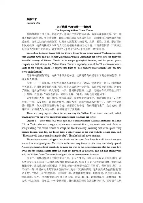
旅游文章Passage One天下绝景气吞云梦——黄鹤楼The Imposing Yellow Crane Tower黄鹤楼雄踞长江之滨,蛇山之首,背倚万户林立的武昌城,面临汹涌浩荡的扬子江,相对古雅清俊晴川阁,登上黄鹤楼,武汉三镇的旖旎风光历历在目,辽阔神州的锦绣山河也遥遥在望。
由于这独特的地理位置,以及前人流传至今的诗词、文赋、楹联、匾额、摩岩石刻和民间故事,使黄鹤楼成为山川与人文景观相互倚重的文化名楼,与湖南岳阳楼、江西滕王阁并称为“江南三大名楼”,素来享有“天下绝景”和“天下江山第一楼”的美誉。
Located on the top of Snake Hill, the Yellow Crane Tower stands against Wuchang, faces the vast Yangtze River and the elegant Qingchuan Pavilion. Ascending the tower, you can enjoy the beautiful scenery of Wuhan. Thanks to its unique geological location, and the poems, prose, couplets and folk stories, the Yellow Crane Tower is reputed as one of the “three famous towers south of the Yangtze River”. It enjoys such titles as “best scenery under heaven” and “the first tower under heaven”.关于黄鹤楼因何而建,流传下来很多的传说,这就更给黄鹤楼增加了几分神秘色彩,引得无数人景仰。
传说一:一千多年前,有位姓辛的老人在蛇山上开了酒店,常客中有一道士,回回喝酒不买酒菜,只用随身带着的水果下酒。
风力发电外文文献翻译中英文

风力发电外文翻译中英文英文Wind power in China – Dream or reality?HubacekAbstractAfter tremendous growth of wind power generation capacity in recent years, China now has 44.7 GW of wind-derived power. Despite the recent growth rates and promises of a bright future, two important issues - the capability of the grid infrastructure and the availability of backup systems - must be critically discussed and tackled in the medium term.The study shows that only a relatively small share of investment goes towards improving and extending the electricity infrastructure which is a precondition for transmitting clean wind energy to the end users. In addition, the backup systems are either geographically too remote from the potential wind power sites or currently financially infeasible. Finally, the introduction of wind power to the coal-dominated energy production system is not problem-free. Frequent ramp ups and downs of coal-fired plants lead to lower energy efficiency and higher emissions, which are likely to negate some of the emission savings from wind power.The current power system is heavily reliant on independently acting but state-owned energy companies optimizing their part of the system, and this is partly incompatible with building a robust system supportingrenewable energy technologies. Hence, strategic, top-down co-ordination and incentives to improve the overall electricity infrastructure is recommended.Keywords: Wind power, China, Power grids, Back-up systems1. IntroductionChina’s wind energy industry has exper ienced a rapid growth over the last decade. Since the promulgation of the first Renewable Energy Law in 2006, the cumulative installed capacity of wind energy amounted to 44.7 GW by the end of 2010 [1]. The newly installed capacity in 2010 reached 18.9 GW which accounted for about 49.5% of new windmills globally. The wind energy potential in China is considerable, though with differing estimates from different sources. According to He et al. [2], the exploitable wind energy potential is 600–1000 GW onshore and 100–200 GW offshore. Without considering the limitations of wind energy such as variable power outputs and seasonal variations, McElroy et al. [3] concluded that if the Chinese government commits to an aggressive low carbon energy future, wind energy is capable of generating 6.96 million GWh of electricity by 2030, which is sufficient to satisfy China’s electricity demand in 2030.The existing literature of wind energy development in China focuses on several discussion themes. The majority of the studies emphasize the importance of government policy on the promotion of wind energyindustry in China [4], [5], [6], [7]. For instance, Lema and Ruby [8] compared the growth of wind generation capacity between 1986 and 2006, and addressed the importance of a coordinated government policy and corresponding incentives. Several studies assessed other issues such as the current status of wind energy development in China [9]; the potential of wind power [10]; the significance of wind turbine manufacturing [11]; wind resource assessment [5]; the application of small-scale wind power in rural areas [12]; clean development mechanism in the promotion of wind energy in China [4], social, economic and technical performance of wind turbines [13] etc.There are few studies which assess the challenge of grid infrastructure in the integration of wind power. For instance, Wang [14] studied grid investment, grid security, long-distance transmission and the difficulties of wind power integration at present. Liao et al. [15] criticised the inadequacy of transmission lines in the wind energy development. However, we believe that there is a need to further investigate these issues since they are critical to the development of wind power in China. Furthermore, wind power is not a stand-alone energy source; it needs to be complemented by other energy sources when wind does not blow. Although the viability and feasibility of the combination of wind power with other power generation technologies have been discussed widely in other countries, none of the papers reviewed thesituation in the Chinese context. In this paper, we discuss and clarify two major issues in light of the Chinese wind energy distribution process: 1) the capability of the grid infrastructure to absorb and transmit large amounts of wind powered electricity, especially when these wind farms are built in remote areas; 2) the choices and viability of the backup systems to cope with the fluctuations of wind electricity output.2. Is the existing power grid infrastructure sufficient?Wind power has to be generated at specific locations with sufficient wind speed and other favourable conditions. In China, most of the wind energy potential is located in remote areas with sparse populations and less developed economies. It means that less wind powered electricity would be consumed close to the source. A large amount of electricity has to be transmitted between supply and demand centres leading to several problems associated with the integration with the national power grid system, including grid investment, grid safety and grid interconnection.2.1. Power grid investmentAlthough the two state grid companies-(SGCC) State Grid Corporation of China and (CSG) China Southern Grid - have invested heavily in grid construction, China’s powe r grid is still insufficient to cope with increasing demand. For example, some coal-fired plants in Jiangsu, which is one of the largest electricity consumers in China, had to drop the load ratio to 60 percent against the international standard of 80percent due to the limited transmission capacity [16]. This situation is a result of an imbalanced investment between power grid construction and power generation capacity. For example, during the Eighth Five-Year Plan, Ninth Five-Year Plan and Tenth Five-Year Plan,1 power grid investments accounted for 13.7%, 37.3% and 30% of total investment in the electricity sector, respectively. The ratio further increased from 31.1% in 2005 to 45.94% in 2008, the cumulative investment in the power grid is still significantly lower than the investments in power generation [17]. Fig. 1 gives a comparison of the ratios of accumulative investments in power grid and power generation in China, the US, Japan, the UK and France since 1978. In most of these countries, more than half of the electric power investment has been made on grid construction. By contrast, the ratio is less than 40% in China.According to the Articles 14 and 21 of the Chinese Renewable Energy Law, the power grid operators are responsible for the grid connection of renewable energy projects. Subsidies are given subject to the length of the grid extension with standard rates. However, Mo [18] found that the subsidies were only sufficient to compensate for capital investment and corresponding interest but excluding operational and maintenance costs.Again, similar to grid connection, grid reinforcement requires significant amounts of capital investment. The Three Gorges power planthas provided an example of large-scale and long-distance electricity transmission in China. Similar to wind power, hydropower is usually situated in less developed areas. As a result, electricity transmission lines are necessary to deliver the electricity to the demand centres where the majority are located; these are the eastern coastal areas and the southern part of China. According to SGCC [19], the grid reinforcement investment of the Three Gorges power plants amounted to 34.4 billion yuan (about 5 billion US dollars). This could be a lot higher in the case of wind power due to a number of reasons. First, the total generating capacity of Three Gorges project is approximately 18.2 GW at this moment and will reach 22.4 GW when fully operating [20], whilst the total generating capacity of the massive wind farms amount to over 100 GW. Hence, more transmission capacities are absolutely necessary. Second, the Three Gorges hydropower plant is located in central China. A number of transmission paths are available, such as the 500 kV DC transmission lines to Shanghai (with a length of 1100 km), Guangzhou (located in Guangdong province, with a length of 1000 km) and Changzhou (located in Jiangsu province, with a length of 1000 km) with a transmission capacity of 3 GW each and the 500 kV AC transmission lines to central China with transmission capacity of 12 GW. By contrast, the majority of wind farm bases, which are located in the northern part of China, are far away from the load centres. For example, Jiuquan locatedin Gansu has a planned generation capacity of 20 GW. The distances from Jiuquan to the demand centres of the Central China grid and the Eastern China grid are 1500 km and 2500 km, respectively. For Xinjiang, the distances are even longer at 2500 km and 4000 km, respectively. As a result, longer transmission lines are required. Fig. 2 depicts the demand centres and wind farms in detail.2.2. Grid safetyThe second problem is related to grid safety. The large-scale penetration of wind electricity leads to voltage instability, flickers and voltage asymmetry which are likely to cause severe damage to the stability of the power grid [21]. For example, voltage stability is a key issue in the grid impact studies of wind power integration. During the continuous operation of wind turbines, a large amount of reactive power is absorbed, which lead to voltage stability deterioration [22]. Furthermore, the significant changes in power supply from wind might damage the power quality [23]. Hence, additional regulation capacity would be needed. However, in a power system with the majority of its power from base load provider, the requirements cannot be met easily [24]. In addition, the possible expansion of existing transmission lines would be necessary since integration of large-scale wind would cause congestion and other grid safety problems in the existing transmission system. For example, Holttinen [23] summarized the majorimpacts of wind power integration on the power grid at the temporal level (the impacts of power outputs at second, minute to year level on the power grid operation) and the spatial level (the impact on local, regional and national power grid). Besides the impacts mentioned above, the authors highlight other impacts such as distribution efficiency, voltage management and adequacy of power on the integration of wind power [23].One of the grid safety problems caused by wind power is reported by the (SERC) State Electricity Regulatory Commission [25]. In February and April of 2011, three large-scale wind power drop-off accidents in Gansu (twice) and Hebei caused power losses of 840.43 MW, 1006.223 MW and 854 MW, respectively, which accounted for 54.4%, 54.17% and 48.5% of the total wind powered outputs. The massive shutdown of wind turbines resulted in serious operational difficulties as frequency dropped to 49.854 Hz, 49.815 Hz and 49.95 Hz in the corresponding regional power grids.The Chinese Renewable Energy Law requires the power grid operators to coordinate the integration of windmills and accept all of the wind powered electricity. However, the power grid companies have been reluctant to do so due to the above mentioned problems as well as technical and economic reasons. For instance, more than one third of the wind turbines in China, amounting to 4 GW capacity, were not connectedto the power grid by the end of 2008 [17]. Given that the national grid in China is exclusively controlled by the power companies –SGCC and CSG - the willingness of these companies to integrate wind energy into the electricity generation systems is critical.2.3. The interconnection of provincial and regional power gridsThe interconnection of trans-regional power grids started at the end of 1980s. A (HVDC) high voltage direct current transmission line was established to link the Gezhouba2 dam with Shanghai which signifies the beginning of regional power grids interconnection. In 2001, two regional power grids, the North China Power Grid and Northeast China Power Grid were interconnected. This was followed by the interconnection of the Central China Power Grid and the North China Power Grid in 2003. In 2005, two other interconnection agreements were made between the South China Power Grid with North, Northeast and Central China Power Grid, and the Northwest China Power Grid and the Central China Power Grid. Finally, in 2009, the interconnection of Central China Power Grid and the East China Power Grid was made. In today’s China, the Chinese power transmission systems are composed of 330 kV and 500 kV transmission lines as the backbone and six interconnected regional power grids and one Tibet power grid [26].It seems that the interconnectivity of regional power grids would help the delivery of wind powered outputs from wind-rich regions todemand centres. However, administrative and technical barriers still exist. First, the interconnectivity among regions is always considered as a backup to contingencies, and could not support the large-scale, long-distance electricity transmission [27]. In addition, the construction of transmission systems is far behind the expansion of wind power. The delivery of large amounts of wind power would be difficult due to limited transmission capacity. Furthermore, the quantity of inter-regional electricity transmission is fixed [27]. Additional wind power in the inter-regional transmission might have to go through complex administrative procedures and may result in profit reductions of conventional power plants.3. Are the backup systems geographically available and technically feasible?Power system operators maintain the security of power supply by holding power reserve capacities in operation. Although terminologies used in the classification of power reserves vary among countries [28], power reserves are always used to keep the production and generation in balance under a range of circumstances, including power plant outages, uncertain variations in load and fluctuations in power generations (such as wind) [29]. As wind speed varies on all time scales (e.g. from seconds to minutes and from months to years), the integration of fluctuating wind power generation induces additional system balancing requirements onthe operational timescale [29].A number of studies have examined the approaches to stabilize the electricity output from wind power plants. For example, Belanger and Gagnon [30] conducted a study on the compensation of wind power fluctuations by using hydropower in Canada. Nema et al. [31] discussed the application of wind combined solar PV power generation systems and concluded that the hybrid energy system was a viable alternative to current power supply systems in remote areas. In China, He et al. [2]investigated the choices of combined power generation systems. The combinations of wind-hydro, wind-diesel, wind-solar and wind-gas power were evaluated respectively. They found that, for instance, the wind-diesel hybrid systems were used at remote areas and isolated islands. This is because the wind-diesel hybrid systems have lower generation efficiency and higher generation costs compared to other generation systems. Currently, the wind-solar hybrid systems are not economically viable for large-scale application; thus, these systems have either been used at remote areas with limited electricity demand (e.g. Gansu Subei and Qinghai Tiansuo) or for lighting in some coastal cities [2]. Liu et al. [32] adopted the EnergyPLAN model to investigate the maximum wind power penetration level in the Chinese power system. The authors derived a conclusion that approximately 26% of national power demand could be supplied by wind power by the end of 2007. However, theauthors fail to explain the provision of power reserves at different time scales due to wind power integration.Because of the smoothing effects of dispersing wind turbines at different locations (as exemplified by Drake and Hubacek [33] for the U.K., Roques [34] for the E.U. and Kempton et al. [35] for the U.S.), the integration of wind power has a very small impact on the primary reserves which are available from seconds to minutes [36]. However, the increased reserve requirements are considerable on secondary reserves (available within 10–15 min) which mainly consist of hydropower plants and gas turbine power plants [29]. Besides, the long-term reserves, which are used to restore secondary reserves after a major power deficit, will be in operation to keep power production and consumption in balance for a longer timescale (from several minutes to several hours). In the following subsection, we examine the availability of power plants providing secondary and long-term reserves and investigate the viability of energy storage system in China.中文中国的风力发电–梦想还是现实?胡巴切克摘要经过近几年风力发电能力的巨大增长,中国现在拥有44.7吉瓦的风力发电。
液压系统外文文献翻译中英文
外文文献翻译(含:英文原文及中文译文)英文原文Hydraulic systemW Arnold1 IntroductionThe hydraulic station is called a hydraulic pump station and is an independent hydraulic device. It is step by step to supply oil. And control the direction of hydraulic oil flow, pressure and flow, suitable for the host and hydraulic equipment can be separated on the various hydraulic machinery.After the purchase, the user only needs to connect the hydraulic station and the actuator (hydraulic or oil motor) on the mainframe with different tubings. The hydraulic machine can realize various specified actions and working cycles.The hydraulic station is a combination of manifolds, pump units or valve assemblies, electrical boxes, and tank electrical boxes. Each part function is:The pump unit is equipped with a motor and an oil pump, which is the power source of the hydraulic station and can convert mechanical energy into hydraulic oil pressure energy.V alve combination - its plate valve is mounted on the vertical plate, and the rear plate is connected with the same function as the manifold.Oil manifolds - assembled from hydraulic valves and channel bodies. It regulates hydraulic oil pressure, direction and flow.Box--a semi-closed container for plate welding. It is also equipped with an oil screen, an air filter, etc., which is used for cooling and filtering of oil and oil.Electrical box - divided into two types: one is to set the external lead terminal board; one is equipped with a full set of control appliances.The working principle of the hydraulic station: The motor drives the oil pump to rotate, then the pump sucks oil from the oil tank and supplies oil, converts the mechanical energy into hydraulic pressure energy, and the hydraulic oil passes through the manifold (or valve assembly) to adjust the direction, pressure and flow and then passes through the external tube. The way to the hydraulic cylinder or oil motor in the hydraulic machinery, so as to control the direction of the hydraulic motor, the strength of the speed and speed, to promote all kinds of hydraulic machinery to do work.(1) Development history of hydraulic pressureThe development history of hydraulics (including hydraulic power, the same below), pneumatics, and seals industry in China can be roughly divided into three stages, namely: the starting stage in the early 1950s to the early 60s; and the professional in the 60s and 70s. The growth stage of the production system; the 80-90's is a stage of rapid development. Among them, the hydraulic industry began in the early 1950s with thedevelopment of hydraulic machines such as Grinding Machines, broaching machines, and profiling lathes, which were produced by the machine tool industry. The hydraulic components were produced by the hydraulic workshop in the machine tool factory, and were produced for self use. After entering the 1960s, the application of hydraulic technology was gradually promoted from the machine tool to the agricultural machinery and engineering machinery. The original hydraulic workshop attached to the main engine plant was independent and became a professional manufacturer of hydraulic components. In the late 1960s and early 1970s, with the continuous development of mechanization of production, particularly in the provision of highly efficient and automated equipment for the second automobile manufacturing plant, the hydraulic component manufacturing industry witnessed rapid development. The batch of small and medium-sized enterprises also began to become specialized manufacturers of hydraulic parts. In 1968, the annual output of hydraulic components in China was close to 200,000 pieces. In 1973, in the fields of machine tools, agricultural machinery, construction machinery and other industries, the professional factory for the production of hydraulic parts has grown to over 100, and its annual output exceeds 1 million pieces. Such an independent hydraulic component manufacturing industry has taken shape. At this time, the hydraulic product has evolved from the original imitation Su product intoa combination of imported technology and self-designed products. The pressure has been developed towards medium and high pressures, and electro-hydraulic servo valves and systems have been developed. The application of hydraulics has been further expanded. The pneumatic industry started a few years later than hydraulics, and it was only in 1967 that it began to establish a professional pneumatic components factory. Pneumatic components began to be manufactured and sold as commodities. Its sealing industry including rubber seals, flexible graphite seals, and mechanical seals started from the production of common O-rings, oil seals, and other extruded rubber seals and asbestos seal products in the early 1950s. In the early 1960s, it began to develop and produce flexible products. Graphite seals and mechanical seals and other products. In the 1970s, a batch of batches of professional production plants began to be established one after another in the systems of the former Ministry of Combustion, the Ministry of Agriculture, and the Ministry of Agricultural Machinery, formally forming the industry, which laid the foundation for the development of the seal industry.In the 1980s, under the guidance of the national policy of reform and opening up, with the continuous development of the machinery industry, the contradiction between the basic components lags behind the host computer has become increasingly prominent and caused the attention of all relevant departments. To this end, the former Ministry of Machinesestablished the General Infrastructure Industry Bureau in 1982, and unified the original pneumatic, hydraulic, and seal specialties that were scattered in the industries of machine tools, agricultural machinery, and construction machinery, etc. The management of a piece of office, so that the industry in the planning, investment, the introduction of technology and scientific research and development and other aspects of the basic parts of the bureau's guidance and support. This has entered a period of rapid development, it has introduced more than 60 foreign advanced technology, of which more than 40 hydraulic, pneumatic 7, after digestion and absorption and technological transformation, are now mass production, and has become the industry's leading products . In recent years, the industry has intensified its technological transformation. From 1991 to 1998, the total investment of national, local, and corporate self-raised funds totaled about 2 billion yuan, of which more than 1.6 billion were hydraulic. After continuous technological transformation and technological breakthroughs, the technical level of a group of major enterprises has been further improved, and technological equipment has also been greatly improved, laying a good foundation for forming a high starting point, specialization, and mass production. In recent years, under the guidance of the principle of common development of multiple ownership systems in the country, various small and medium-sized enterprises with different ownership have rapidly emerged and haveshown great vitality. With the further opening up of the country, foreign-funded enterprises have developed rapidly, which plays an important role in raising industry standards and expanding exports. So far China has established joint ventures with famous manufacturers in the United States, Germany, Japan and other countries or directly established piston pumps/motors, planetary speed reducers, hydraulic control valves, steering gears, hydraulic systems, hydrostatic transmissions, and hydraulic components. The company has more than 50 manufacturing enterprises such as castings, pneumatic control valves, cylinders, gas processing triplets, rubber seals, and mechanical seals, and has attracted more than 200 million U.S. dollars in foreign capital.(2) Current statusBasic profileAfter more than 40 years of hard work, China's hydraulics, pneumatics and seals industry has formed a complete industrial system with a certain level of production capacity and technical level. According to the statistics of the third n ational industrial census in 1995, China’s state-owned, privately-owned, cooperative, village-run, individual, and “funded enterprises” have annual sales income of more than 1 million yuan in hydraulic, pneumatic, and seal industrial townships and above. There are a total of more than 1,300 companies, including about 700 hydraulics, and about 300 pneumatic and sealing parts. According to thestatistics of the international industry in 1996, the total output value of the hydraulic industry in China was about 2.448 billion yuan, accounting for the 6th in the world; the total output value of the pneumatic industry was about 419 million yuan, accounting for the world’s10 people.2. Current supply and demand profileWith the introduction of technology, independent development and technological transformation, the technical level of the first batch of high-pressure plunger pumps, vane pumps, gear pumps, general hydraulic valves, oil cylinders, oil-free pneumatic components and various types of seals has become remarkable. Improve, and can be stable mass production, provide guarantees for all types of host to improve product quality. In addition, certain achievements have also been made in the aspects of CAD, pollution control, and proportional servo technology for hydraulic pneumatic components and systems, and have been used for production. So far, the hydraulic, pneumatic and seal products have a total of about 3,000 varieties and more than 23,000 specifications. Among them, there are about 1,200 types of hydraulic pressure, more than 10,000 specifications (including 60 types of hydrodynamic products, 500 specifications); about 1350 types of pneumatic, more than 8,000 specifications; there are also 350 types of rubber seals, more than 5000 The specifications are now basically able to adapt to the general needs ofvarious types of mainframe products. The matching rate for major equipment sets can reach more than 60%, and a small amount of exports has started.In 1998, the domestic production of hydraulic components was 4.8 million pieces, with sales of about 2.8 billion yuan (of which mechanical systems accounted for 70%); output of pneumatic components was 3.6 million pieces, and sales were about 550 million yuan (including mechanical systems accounting for about 60%) The production of seals is about 800 million pieces, and the sales volume is about 1 billion yuan (including about 50% of mechanical systems). According to the statistics of the annual report of the China Hydraulic and Pneumatic Sealing Industry Association in 1998, the production and sales rate of hydraulic products was 97.5% (101% of hydraulic power), 95.9% of air pressure, and 98.7% of seal. This fully reflects the basic convergence of production and sales.Although China's hydraulic, pneumatic and sealing industries have made great progress, there are still many gaps compared with the development needs of the mainframe and the world's advanced level, which are mainly reflected in the variety, performance and reliability of products. . Take hydraulic products as an example, the product varieties are only 1/3 of the foreign country, and the life expectancy is 1/2 of that of foreign countries. In order to meet the needs of key hosts, imported hosts, and majortechnical equipment, China has a large number of imported hydraulic, pneumatic, and sealing products every year. According to customs statistics and relevant data analysis, in 1998, the import volume of hydraulic, pneumatic and seal products was about 200 million U.S. dollars, of which the hydraulic pressure was about 140 million U.S. dollars, the pneumatics were 30 million U.S. dollars, and the seal was about 0.3 billion U.S. dollars. The year is slightly lower. In terms of amount, the current domestic market share of imported products is about 30%. In 1998, the total demand for hydraulic parts in the domestic market was about 6 million pieces, and the total sales volume was 4 billion yuan; the total demand for pneumatic parts was about 5 million pieces, and the total sales volume was over 700 million yuan; the total demand for seals was about 1.1 billion yuan. Pieces, total sales of about 1.3 billion yuan. (3) Future developments1. The main factors affecting development(1) The company's product development capability is not strong, and the level and speed of technology development can not fully meet the current needs for advanced mainframe products, major technical equipment and imported equipment and maintenance;(2) Many companies have lagged behind in manufacturing process, equipment level and management level, and their sense of quality is not strong, resulting in low level of product performance, unstable quality,poor reliability, and insufficiency of service, and lack of user satisfaction. And trusted branded products;(3) The degree of professional specialization in the industry is low, the power is scattered, the duplication of the low level is serious, the product convergence between the region and the enterprise leads to blind competition, and the prices are reduced each other, thus the efficiency of the enterprise is reduced, the funds are lacking, and the turnover is difficult. Insufficient investment in development and technological transformation has severely restricted the overall level of the industry and its competitive strength.(4) When the degree of internationalization of the domestic market is increasing, foreign companies have gradually entered the Chinese market to participate in competition, coupled with the rise of domestic private, cooperative, foreign-funded, and individual enterprises, resulting in increasing impact on state-owned enterprises. .2. Development trendWith the continuous deepening of the socialist market economy, the relationship between supply and demand in the hydraulic, pneumatic and sealed products has undergone major changes. The seller market characterized by “shortage” has basically become a buyer’s market characterized by “structured surplus”. Replaced by. From the perspective of overall capacity, it is already in a trend of oversupply, and in particular,general low-grade hydraulic, pneumatic and seals are generally oversupply; and like high-tech products with high technological content and high value and high value-added products that are urgently needed by the host, Can not meet the needs of the market, can only rely on imports. After China's entry into the WTO, its impact may be greater. Therefore, during the “10th Five-Y ear Plan” period, the growth of the industry’s output value must not only rely on the growth of quantity. Instead, it should focus on the structural contradiction of the industry and intensify efforts to adjust the industrial structure and product structure. It should be based on the improvement of quality. Product technology upgrades in order to adapt to and stimulate market demand, and seek greater development.2. Hydraulic application on power slide(1) Introduction of Power Sliding TableUsing the binding force curve diagram and the state space analysis method to analyze and study the sliding effect and the smoothness of the sliding table of the combined machine tool, the dynamics of the hydraulic drive system of the sliding table—the self-regulating back pressure regulating system are established. mathematical model. Through the digital simulation system of the computer, the causes and main influencing factors of the slide impact and the motion instability are analyzed. What kind of conclusions can be drawn from those, if we canreasonably design the structural dimensions of hydraulic cylinders and self-regulating back pressure regulators ——The symbols used in the text are as follows:s 1 - flow source, that is, the flow rate of the governor valve outlet;S el —— sliding friction of the sliding table;R - the equivalent viscous friction coefficient of the slide;I 1 - quality of slides and cylinders;12 - self-adjusting back pressure valve core quality;C 1, c 2 - liquid volume without cylinder chamber and rod chamber;C 2 - Self-adjusting back pressure valve spring compliance;R 1, R2 - Self-adjusting back pressure valve damping orifice fluid resistance;R 9 - Self-adjusting back pressure valve valve fluid resistance;S e2——initial pre-tightening force of self-adjusting back pressure valve spring;I 4, I5 - Equivalent liquid sense of the pipeline;C 5, C 6 - equivalent liquid capacity of the pipeline;R 5, R7 - Equivalent liquid resistance of the pipeline;V 3, V4 - cylinder rodless cavity and rod cavity volume;P 3, P4—pressure of the rodless cavity and rod cavity of the cylinder;F - the slide bears the load;V - speed of slide motion;In this paper, the power bond diagram and the state space splitting method are used to establish the system's motion mathematical model, and the dynamic characteristics of the slide table can be significantly improved.In the normal operation of the combined machine tool, the magnitude of the speed of the slide, its direction and the load changes it undergoes will affect its performance in varying degrees. Especially in the process of work-in-process, the unsteady movement caused by the advancing of the load on the slide table and the cyclical change of the load will affect the surface quality of the workpiece to be machined. In severe cases, the tool will break. According to the requirements of the Dalian Machine Tool Plant, the author used the binding force curve diagram and the state space analysis method to establish a dynamic mathematical model of a self-adjusting back pressure and speed adjustment system for the new hydraulic drive system of the combined machine tool slide. In order to improve the dynamic characteristics of the sliding table, it is necessary to analyze the causes and main influencing factors of the impetus and movement of the sliding table. However, it must pass the computer's digital simulation and the final results obtained from the research.(2) Dynamic Mathematical ModelThe working principle diagram of the self-adjusting back pressure speedregulation system of the combined machine tool slide hydraulic drive system is shown in the figure. This system is used to complete the work-cycle-stop-rewind. When the sliding table is working, the three-position four-way reversing valve is in the illustrated position. The oil supply pressure of the oil pump will remain approximately constant under the effective action of the overflow valve, and the oil flow passes through the reversing valve and adjusts the speed. The valve enters the rodless chamber of the cylinder to push the slide forward. At the same time, the pressurized oil discharged from the rod chamber of the cylinder will flow back to the tank through the self-regulating back pressure valve and the reversing valve. During this process, there was no change in the operating status of both the one-way valve and the relief valve. The complex and nonlinear system of the hydraulic drive system of the self-adjusting back pressure governor system is a kind of self-adjusting back-pressure governor system. To facilitate the study of its dynamic characteristics, a simple and reasonable dynamic mathematical model that only considers the main influencing factors is established. Especially important [1][2]. From the theoretical analysis and the experimental study, we can see that the system process time is much longer than the process time of the speed control valve. When the effective pressure bearing area of the rodless cavity of the fuel tank is large, the flow rate at the outlet of the speed control valve is instantaneous. The overshoot is reflected in thesmall change in speed of the slide motion [2]. In order to further broaden and deeply study the dynamic characteristics of the system so that the research work can be effectively performed on a miniature computer, this article will further simplify the original model [2], assuming that the speed control valve is output during the entire system pass. When the flow is constant, this is considered to be the source of the flow. The schematic diagram of the dynamic model structure of this system is shown in Fig. 2. It consists of a cylinder, a sliding table, a self-adjusting back pressure valve, and a connecting pipe.The power bond graph is a power flow graph. It is based on the transmission mode of the system energy, based on the actual structure, and uses the centralized parameters to represent the role of the subsystems abstractly as a resistive element R, a perceptual element I, and a capacitive element. Three kinds of role of C. Using this method, the physical concept of modeling is clear, and combined with the state-space analysis method, the linear system can be described and analyzed more accurately. This method is an effective method to study the dynamic characteristics of complex nonlinear systems in the time domain. According to the main characteristics of each component of the self-adjusting back pressure control system and the modeling rules [1], the power bond diagram of the system is obtained. The upper half of each key in the figure represents the power flow. The two variables that makeup the power are the force variables (oil pressure P and force F) and the flow variables (flow q and velocity v). The O node indicates that the system is connected in parallel, and the force variables on each key are equal and the sum of the flow variables is zero; 1 The nodes represent the series connection in the system, the flow variables on each key are equal and the sum of the force variables is Zero. TF denotes a transformer between different energy forms. The TF subscripted letter represents the conversion ratio of the flow variable or the force variable. The short bar on the key indicates the causal relationship between the two variables on the key. The full arrow indicates the control relationship. There are integral or differential relationships between the force and flow variables of the capacitive and perceptual elements in the three types of action elements. Therefore, a complex nonlinear equation of state with nine state variables can be derived from Fig. 3 . In this paper, the research on the dynamic characteristics of the sliding table starts from the two aspects of the slide's hedging and the smoothness of the motion. The fourth-order fixed-length Runge-Kutta is used for digital simulation on the IBM-PC microcomputer.(3) Slide advanceThe swaying phenomenon of the slide table is caused by the sudden disappearance of the load acting on the slide table (such as drilling work conditions). In this process, the table load F, the moving speed V, and thepressure in the two chambers of the cylinder P3 and P4 can be seen from the simulation results in Fig. 4. When the sliding table moves at a uniform speed under the load, the oil pressure in the rodless cavity of the oil cylinder is high, and a large amount of energy is accumulated in the oil. When the load suddenly disappears, the oil pressure of the cavity is rapidly reduced, and the oil is rapidly reduced. When the high-pressure state is transferred to the low-pressure state, a lot of energy is released to the system, resulting in a high-speed forward impact of the slide. However, the front slide of the sliding table causes the pressure in the rod cavity of the oil cylinder to cause the back pressure to rise, thereby consuming part of the energy in the system, which has a certain effect on the kicking of the slide table. We should see that in the studied system, the inlet pressure of the self-adjusting back pressure valve is subject to the comprehensive effect of the two-chamber oil pressure of the oil cylinder. When the load suddenly disappears, the pressure of the self-adjusting back pressure valve rapidly rises and stably exceeds the initial back pressure value. It can be seen from the figure that self-adjusting back pressure in the speed control system when the load disappears, the back pressure of the cylinder rises more than the traditional speed control system, so the oil in the rod cavity of the cylinder absorbs more energy, resulting in the amount of forward momentum of the slide It will be about 20% smaller than traditionalspeed control systems. It can be seen from this that the use of self-adjusting back-gear speed control system as a drive system slider has good characteristics in suppressing the forward punch, in which the self-adjusting back pressure valve plays a very large role.(4) The smoothness of the slideWhen the load acting on the slide changes periodically (such as in the case of milling), the speed of the slide will have to fluctuate. In order to ensure the processing quality requirements, it must reduce its speed fluctuation range as much as possible. From the perspective of the convenience of the discussion of the problem, assume that the load changes according to a sine wave law, and the resulting digital simulation results are shown in Figure 5. From this we can see that this system has the same variation rules and very close numerical values as the conventional speed control system. The reason is that when the change of the load is not large, the pressure in the two chambers of the fuel tank will not have a large change, which will eventually lead to the self-regulating back pressure valve not showing its effect clearly.(5) Improvement measuresThe results of the research show that the dynamic performance of a sliding table with self-regulating back pressure control system as a drive system is better than that of a traditional speed control system. To reduce the amount of kick in the slide, it is necessary to rapidly increase the backpressure of the rod cavity when the load disappears. To increase the smoothness of the sliding table, it is necessary to increase the rigidity of the system. The main measure is to reduce the volume of oil. From the system structure, it is known that the cylinder has a large volume between the rod cavity and the oil discharge pipe, as shown in Fig. 6a. Its existence in terms of delay and attenuation of the self-regulating back pressure valve function, on the other hand, also reduces the rigidity of the system, it will limit the further improvement of the propulsion characteristics and the smoothness of the motion. Thus, improving the dynamic characteristics of the sliding table can be handled by two methods: changing the cylinder volume or changing the size of the self-regulating back pressure valve. Through the simulation calculation of the structural parameters of the system and the comparison of the results, it can be concluded that the ratio of the volume V4 between the rod cavity and the oil discharge pipe to the volume V3 between the rodless cavity and the oil inlet pipe is changed from 5.5 to 5.5. At 1 oclock, as shown in the figure, the diameter of the bottom end of the self-adjusting back pressure valve is increased from the original 10mm to 13mm, and the length of the damper triangle groove is reduced from the original lmm to 0.7mm, which will enable the front of the slide table. The impulse is reduced by 30%, the transition time is obviously shortened, and the smoothness of the slide motion will also be greatly improved.中文译文液压系统W Arnold1. 绪论液压站称液压泵站,是独立的液压装置。
机器人外文文献翻译、中英文翻译
外文资料robotThe industrial robot is a tool that is used in the manufacturing environment to increase productivity. It can be used to do routine and tedious assembly line jobs,or it can perform jobs that might be hazardous to the human worker . For example ,one of the first industrial robot was used to replace the nuclear fuel rods in nuclear power plants. A human doing this job might be exposed to harmful amounts of radiation. The industrial robot can also operate on the assembly line,putting together small components,such as placing electronic components on a printed circuit board. Thus,the human worker can be relieved of the routine operation of this tedious task. Robots can also be programmed to defuse bombs,to serve the handicapped,and to perform functions in numerous applications in our society.The robot can be thought of as a machine that will move an end-of-tool ,sensor ,and/or gripper to a preprogrammed location. When the robot arrives at this location,it will perform some sort of task .This task could be welding,sealing,machine loading ,machine unloading,or a host of assembly jobs. Generally,this work can be accomplished without the involvement of a human being,except for programming and for turning the system on and off.The basic terminology of robotic systems is introduced in the following:1. A robot is a reprogrammable ,multifunctional manipulator designed to move parts,material,tool,or special devices through variable programmed motions for the performance of a variety of different task. This basic definition leads to other definitions,presented in the following paragraphs,that give acomplete picture of a robotic system.2. Preprogrammed locations are paths that the robot must follow to accomplish work,At some of these locations,the robot will stop and perform some operation ,such as assembly of parts,spray painting ,or welding .These preprogrammed locations are stored in the robot’s memory and are recalled later for continuousoperation.Furthermore,these preprogrammed locations,as well as other program data,can be changed later as the work requirements change.Thus,with regard to this programming feature,an industrial robot is very much like a computer ,where data can be stoned and later recalled and edited.3. The manipulator is the arm of the robot .It allows the robot to bend,reach,and twist.This movement is provided by the manipulator’s axes,also called the degrees of freedom of the robot .A robot can have from 3 to 16 axes.The term degrees of freedom will always relate to the number of axes found on a robot.4. The tooling and frippers are not part the robotic system itself;rather,they are attachments that fit on the end of the robot’s arm. These attachments connected to the end of the robot’s arm allow the robot to lift parts,spot-weld ,paint,arc-weld,drill,deburr,and do a variety of tasks,depending on what is required of the robot.5. The robotic system can control the work cell of the operating robot.The work cell of the robot is the total environment in which the robot must perform itstask.Included within this cell may be the controller ,the robot manipulator ,a work table ,safety features,or a conveyor.All the equipment that is required in order for the robot to do its job is included in the work cell .In addition,signals from outside devices can communicate with the robot to tell the robot when it should parts,pick up parts,or unload parts to a conveyor.The robotic system has three basic components: the manipulator,the controller,and the power source.A.ManipulatorThe manipulator ,which does the physical work of the robotic system,consists of two sections:the mechanical section and the attached appendage.The manipulator also has a base to which the appendages are attached.Fig.1 illustrates the connectionof the base and the appendage of a robot.图1.Basic components of a robot’s manipulatorThe base of the manipulator is usually fixed to the floor of the work area. Sometimes,though,the base may be movable. In this case,the base is attached to either a rail or a track,allowing the manipulator to be moved from one location to anther.As mentioned previously ,the appendage extends from the base of the robot. The appendage is the arm of the robot. It can be either a straight ,movable arm or a jointed arm. The jointed arm is also known as an articulated arm.The appendages of the robot manipulator give the manipulator its various axes of motion. These axes are attached to a fixed base ,which,in turn,is secured to a mounting. This mounting ensures that the manipulator will in one location.At the end of the arm ,a wrist(see Fig 2)is connected. The wrist is made up of additional axes and a wrist flange. The wrist flange allows the robot user to connect different tooling to the wrist for different jobs.图2.Elements of a work cell from the topThe manipulator’s axes allow it to perform work within a certain area. The area is called the work cell of the robot ,and its size corresponds to the size of the manipulator.(Fid2)illustrates the work cell of a typical assembly ro bot.As the robot’s physical size increases,the size of the work cell must also increase.The movement of the manipulator is controlled by actuator,or drive systems.The actuator,or drive systems,allows the various axes to move within the work cell. The drive system can use electric,hydraulic,or pneumatic power.The energy developed by the drive system is converted to mechanical power by various mechanical power systems.The drive systems are coupled through mechanical linkages.These linkages,in turn,drive the different axes of the robot.The mechanical linkages may be composed of chain,gear,and ball screws.B.ControllerThe controller in the robotic system is the heart of the operation .The controller stores preprogrammed information for later recall,controls peripheral devices,and communicates with computers within the plant for constant updates in production.The controller is used to control the robot manipulator’s movements as well as to control peripheral components within the work cell. The user can program the movements of the manipulator into the controller through the use of a hard-held teach pendant.This information is stored in the memory of the controller for later recall.The controller stores all program data for the robotic system.It can store several differentprograms,and any of these programs can be edited.The controller is also required to communicate with peripheral equipment within the work cell. For example,the controller has an input line that identifies when a machining operation is completed.When the machine cycle is completed,the input line turn on telling the controller to position the manipulator so that it can pick up the finished part.Then ,a new part is picked up by the manipulator and placed into the machine.Next,the controller signals the machine to start operation.The controller can be made from mechanically operated drums that step through a sequence of events.This type of controller operates with a very simple robotic system.The controllers found on the majority of robotic systems are more complex devices and represent state-of-the-art eletronoics.That is,they are microprocessor-operated.these microprocessors are either 8-bit,16-bit,or 32-bit processors.this power allows the controller to be very flexible in its operation.The controller can send electric signals over communication lines that allow it to talk with the various axes of the manipulator. This two-way communication between the robot manipulator and the controller maintains a constant update of the end the operation of the system.The controller also controls any tooling placed on the end of the robot’s wrist.The controller also has the job of communicating with the different plant computers. The communication link establishes the robot as part a computer-assisted manufacturing (CAM)system.As the basic definition stated,the robot is a reprogrammable,multifunctional manipulator.Therefore,the controller must contain some of memory stage. The microprocessor-based systems operates in conjunction with solid-state devices.These memory devices may be magnetic bubbles,random-access memory,floppy disks,or magnetic tape.Each memory storage device stores program information fir or for editing.C.power supplyThe power supply is the unit that supplies power to the controller and the manipulator. The type of power are delivered to the robotic system. One type of power is the AC power for operation of the controller. The other type of power isused for driving the various axes of the manipulator. For example,if the robot manipulator is controlled by hydraulic or pneumatic drives,control signals are sent to these devices causing motion of the robot.For each robotic system,power is required to operate the manipulator .This power can be developed from either a hydraulic power source,a pneumatic power source,or an electric power source.There power sources are part of the total components of the robotic work cell.中文翻译机器人工业机器人是在生产环境中用以提高生产效率的工具,它能做常规乏味的装配线工作,或能做那些对于工人来说是危险的工作,例如,第一代工业机器人是用来在核电站中更换核燃料棒,如果人去做这项工作,将会遭受有害放射线的辐射。
外文翻译 英文
2. WHAT CONSTITUTES FAIR DEALINGWEINBERGER v. UOP, INC.457 A.2d 701 (Del.Supr.19a3).MOORE, JUSTICE.This post-trial appeal was reheard en banc from a decision of the Court of Chancery. It was brought by the class action plaintiff below, a former shareholder of UOP, Inc., who challenged the elimination of UOP's minority shareholders by a cash-out merger between UOP and its majority owner, The Signal Companies, Inc. Originally, the defendants in this action were Signal, UOP, certain officers and directors of those companies, and UOP's investment banker, Lehman Brothers Kuhn Loeb, Inc. The present Chancellor held that the terms of the merger were fair to the plaintiff and the other minority shareholders of UOP. Accordingly, he entered judgment in favor of the defendants.Numerous points were raised by the parties, but we address only the following questions presented by the trial court's opinion:1) The plaintiffs duty to plead sufficient facts demonstrating the unfairness of the challenged merger;2) The burden of proof upon the parties where the merger has been approved by the purportedly informed vote of a majority of the minority shareholders;3) The fairness of the merger in terms of adequacy of the defendants' disclosures to the minority shareholders;4) The fairness of the merger in terms of adequacy of the price paid for the minority shares and the remedy appropriate to that issue; and5) The continued force and effect of Singer v. Magnavox Co., Del.Supr., 380 A.2d 969, 980 (1977), and its progeny.In ruling for the defendants, the Chancellor re-stated his earlier conclusion that the plaintiff in a suit challenging a cash-out merger must allege specific acts of fraud, misrepresentation or other items of misconduct to demonstrate the unfairness of the merger terms to the minority. We approve this rule and affirm it.The Chancellor also held that even though the ultimate burden of proof is on the majority shareholder to show by a preponderance of the evidence that the transaction is fair, it is first the burden of the plaintiff attacking the merger to demonstrate some basis for invoking the fairness obligation. We agree with that principle. However, where corporate action has been approved by an informed vote of a majority of the minority shareholders, we conclude that the burden entirely shifts ^ to the plaintiff to show that the transaction was unfair to the minority^- But in all this, the burden clearly remains on those relying on the vote to show that they completely disclosed all material facts relevant to the transaction.Here, the record does not support a conclusion that the minority stockholder vote was an informed one. Material information, necessary to acquaint those shareholders with the bargaining positions of Signal and UOP, was withheld under circumstances amounting to a breach of fiduciary duty. We therefore conclude that this merger does not meet the test of fairness, at least as we address that concept, and no burden thus shifted to the plaintiff by reason of the minority shareholder vote. Accordingly, we reverse and remand for further proceedings consistent herewith.In considering the nature of the remedy available under our law to minority shareholders in a cash-out merger, we believe that it is, and hereafter should be, an appraisal under 8 Del.C. § 262 as hereinafter construed. We therefore overrule Lynch v. Vickers Energy Corp., Del. Supr., 429 A.2d 497 (1981) {Lynch II) to the extent that it purports to limit a stockholder's monetary relief to a specific damage formula. But to give full effect to section 262 within the framework of the General Corporation Law we adopt a more liberal, less rigid and stylized, approach to the valuation process than has heretofore been permitted by our courts. While the present state of these proceedings does not admit the plaintiff to the appraisal remedy per se, the practical effect of the remedy we do grant him will be co-extensive with the liberalized valuation and appraisal methods we herein approve for cases coming after this decision.Our treatment of these matters has necessarily led us to a reconsideration of the business purpose rule announced in the trilogy of Singer A v. Magnavox Co., supra; Tanzer v. International General Industries, JT > Inc., DeL.Supr., 379 A.2d 1121 (1977); and Roland International Corp. v. Najjar, Del.Supr., 407 A.2d 1032 (1979). For the reasons hereafter set forth we consider that the business purpose requirement of these cases v J is no longer the law of Delaware.The facts found by the trial court, pertinent to the issues before us, are supported by the record, and we draw from them as set out in the Chancellor's opinion.Signal is a diversified, technically based company operating through various subsidiaries. Its stock is publicly traded on the New York, Philadelphia and Pacific Stock Exchanges. UOP, formerly known as Universal Oil Products Company, was a diversified industrial company engaged in various lines of business, including petroleum and petro-chemical services and related products, construction, fabricated metal products, transportation equipment products, chemicals and plastics, and other products and services including land development, lumber products and waste disposal. Its stock was publicly held and listed on the New York Stock Exchange.In 1974 Signal sold one of its wholly-owned subsidiaries for $420,000,000 in cash. See Gimbel v. Signal Companies, Inc., Del.Ch., 316 A.2d 599, aff’d, Del.Supr., 316 A.2d 619 (1974). While looking to invest this cash surplus, Signal became interested in UOP as a possible acquisition. Friendly negotiations ensued, and Signal proposed to acquire a controlling interest in UOP at a price of $19 per share. UOP's representatives sought $25 per share. In the arm's length bargaining that followed, an understanding was reached whereby Signal agreed to purchase from UOP 1,500,000 shares of UOP's authorized but unissued stock at $21 per share.This purchase was contingent upon Signal^ making a successful cash tender offer for 4,300,000 publicly held shares of UOP, also at a price of $21 per share. This combined method of acquisition permitted Signal to acquire 5,800,000 shares of stock, representing 50.5% of UOP's outstanding shares. The UOP board of directors advised the company's shareholders that it had no objection to Signal's tender offer at that price. Immediately before the announcement of the tender offer, UOP's common stock had been trading on the New York Stock Exchange at a fraction under $14 per share.The negotiations between Signal and UOP occurred during April 1975, and the resulting tender offer was greatly oversubscribed. However, Signal limited its total purchase of the tendered shares so that, when coupled with the stock bought from UOP, it had achieved its goalof becoming a 50.5% shareholderAlthough UOP’ board consisted of thirteen directors, Signal nominated and elected only six. Of these, five were either directors or employees of Signal. The sixth, a partner in the banking firm of Lazard Freres & Co., had been one of Signal's representatives in the negotiations and bargaining with UOP concerning the tender offer and purchase price of the UOP shares.However, the president and chief executive officer of UOP retired during 1975, and Signal caused him to be replaced by James V. Crawford, a long-time employee and senior executive vice president of one of Signal's wholly-owned subsidiaries. Crawford succeeded his predecessor on UOP's board of directors and also was made a director of Signal.By the end of 1977 Signal basically was unsuccessful in finding other suitable investment candidates for its excess cash, and by February 1978 considered that it had no other realistic acquisitions available to it on a friendly basis. Once again its attention turned to UOP.The trial court found that at the instigation of certain Signal management personnel, including William W. Walkup, its board chairman, and Forrest N. Shumway, its president, a feasibility study was made concerning the possible acquisition of the balance of UOP's outstanding shares. This study was performed by two Signal officers, Charles S. Arledge, vice president (director of planning), and Andrew J. Chitiea, senior vice president (chief financial officer). Messrs. Walkup, Shumway, Arledge and Chitiea were all directors of UOP in addition to their membership on the Signal board.Arledge and Chitiea concluded that it would be a good investment for Signal to acquire the remaining 49.5% of UOP shares at any price up to $24 each. Their report was discussed between Walkup and Shumway who, along with Arledge, Chitiea and Brewster L. Arms, internal counsel for Signal, constituted Signal's senior management. In particular, they talked about the proper price to be paid if the acquisition was pursued, purportedly keeping in mind that as UOP's majority shareholder, Signal owed a fiduciary responsibility to both its own stockholders as well as to UOP's minority. It was ultimately agreed that a meeting of Signal's Executive Committee would be called to propose that Signal acquire the remaining outstanding stock of UOP through a cash-out merger in the range of $20 to $21 per share.The Executive Committee meeting was set for February 28, 1978. As a courtesy, UOP's president, Crawford, was invited to attend, although he was not a member of Signal's executive committee. On his arrival, and prior to the meeting, Crawford was asked to meet privately with Walkup and Shumway. He was then told of Signal's plan to acquire full ownership of UOP and was asked for his reaction to the proposed price range of $20 to $21 per share. Crawford said he thought such a price would be "generous", and that it was certainly one which should be submitted to UOP's minority shareholders for their ultimate consideration. He stated, however, that Signal's 100% ownership could cause internal problems at UOP. He believed that employees would have to be given some assurance of their future place in a fully- owned Signal subsidiary. Otherwise, he feared the departure of essential personnel. Also, many of UOP's key employees had stock option incentive programs which would be wiped out by a merger. Crawford therefore urged that some adjustment would have to be made, such as providing a comparable incentive in Signal's shares, if after the merger he was to maintain his quality of personnel and efficiency at UOP.Thus, Crawford voiced no objection to the $20 to $21 price range, nor did he suggest that Signal should consider paying more than $21 per share for the minority interests. Later, at the Executive Committee meeting the same factors were discussed, with Crawford repeating the position he earlier took with Walkup and Shumway. Also considered was the 1975 tender offer andthe fact that it had been greatly oversubscribed at $21 per share. For many reasons, Signal's manage¬ment concluded that the acquisition of UOP's minority shares provided the solution to a number of its business problems.Thus, it was the consensus that a price of $20 to $21 per share would be fair to both Signal and the minority shareholders of UOP. Signal's executive committee authorized its management "to negotiate" with UOP "for a cash acquisition of the minority ownership in UOP, Inc., with the intention of presenting a proposal to [Signal's] board of directors * * * on March 6, 1978". Immediately after this February 28, 1978 meeting, Signal issued a press release stating: The Signal Companies, Inc. and UOP, Inc. are conducting negotiations for the acquisition for cash by Signal of the 49.5 per cent of UOP which it does not presently own, announced Forrest N. Shumway, president and chief executive officer of Signal, and James V. Crawford, UOP president. Price and other terms of the proposed transaction have not y et been finalized and would be subject to approval of the boards of directors of Signal and UOP, scheduled to meet early next week, the stockholders of UOP and certain federal agencies.The announcement also referred to the fact that the closing price of UOP's common stock on that day was $14.50 per share.Two days later, on March 2, 1978, Signal issued a second press release stating that its management would recommend a price in the range of $20 to $21 per share for UOP's 49.5% minority interest. This announcement referred to Signal's earlier statement that "negotiations" were being conducted for the acquisition of the minority shares.Between Tuesday, February 28, 1978 and Monday, March 6,1978, a total of four business days, Crawford spoke by telephone with all of UOP's non-Signal, i.e., outside, directors. Also during that period, Crawford retained Lehman Brothers to render a fairness opinion as to the price offered the minority for its stock. He gave two reasons for this choice. First, the time schedule between the announcement and the board meetings was short (by then only three business days) and since Lehman Brothers had been acting as UOP's investment banker for many years, Crawford felt that it would be in the best position to respond on such brief notice. Second, James W. Glanville, a long-time director of UOP and a partner in Lehman Brothers, had acted as a financial advisor to UOP for many years. Crawford believed that Glanville's familiarity with UOP, as a member of its board, would also be of assistance in enabling Lehman Brothers to render a fairness opinion within the existing time constraints.Crawford telephoned Glanville, who gave his assurance that Lehman Brothers had no conflicts that would prevent it from accepting the task. Glanville's immediate personal reaction was that a price of $20 to $21 would certainly be fair, since it represented almost a 50% premium over UOP's market price. Glanville sought a $250,000 fee for Lehman Brothers' services, but Crawford thought this too much. After further discussions Glanville finally agreed that Lehman Brothers would render its fairness opinion for $150,000.During this period Crawford also had several telephone contacts with Signal officials. In only one of them, however, was the price of the shares discussed. In a conversation with Walkup, Crawford advised that as a result of his communications with UOP's non-Signal directors, it was his feeling that the price would have to be the top of the proposed range, or $21 per share, if the approval of UOP's outside directors was to be obtained. But again, he did not seek any price higher than $21.Glanville assembled a three-man Lehman Brothers team to do the work on the fairness opinion. These persons examined relevant documents and information concerning UOP, including its annual reports and its Securities and Exchange Commission filings from 1973 through 1976, as well as its audited financial statements for 1977, its interim reports to shareholders, and its recent and historical market prices and trading volumes. In addition, on Friday, March 3, 1978, two members of the Lehman Brothers team flew to UOP's headquarters in Des Plaines, Illinois, to perform a "due diligence" visit, during the course of which they interviewed Crawford as well as UOP's general counsel, its chief financial officer, and other key executives and personnel.As a result, the Lehman Brothers team concluded that "the price of either $20 or $21 would be a fair price for the remaining shares of UOP". They telephoned this impression to Glanville, who was spending the weekend in Vermont.On Monday morning, March 6, 1978, Glanville and the senior member of the Lehman Brothers team flew to Des Plaines to attend the scheduled UOP directors meeting. Glanville looked over the assembled information during the flight. The two had with them the draft of a "fairness opinion letter" in which the price had been left blank. Either during or immediately prior to the directors' meeting, the two-page "fairness opinion letter" was typed in final form and the price of $21 per share was inserted.On March 6, 1978, both the Signal and UOP boards were convened to consider the proposed merger. Telephone communications were maintained between the two meetings. Walkup, Signal's board chairman, and also a UOP director, attended UOP's meeting with Crawford in order to present Signal's position and answer any questions that UOP's non-Signal directors might have. Arledge and Chitiea, along with Signal's other designees on UOP's board, participated by conference telephone. All of UOP's outside directors attended the meeting either in person or by conference telephone.First, Signal's board unanimously adopted a resolution authorizing Signal to propose to UOP a cash merger of $21 per share as outlined in a certain merger agreement, and other supporting documents. This proposal required that the merger be approved by a majority of UOP's outstanding minority shares voting at the stockholders meeting at which the merger would be considered, and that the minority shares voting in favor of the merger, when coupled with Signal's 50.5% interest would have to comprise at least two-thirds of all UOP shares. Otherwise the proposed merger would be deemed disapproved.UOP's board then considered the proposal. Copies of the agreement were delivered to the directors in attendance, and other copies had been forwarded earlier to the directors participating by telephone. They also had before them UOP financial data for 1974-1977, UOP's most recent financial statements, market price information, and budget projections for 1978. In addition they had Lehman Brothers' hurriedly prepared fairness opinion letter finding the price of $21 to be fair. Glanville, the Lehman Brothers partner, and UOP director, commented on the information that had gone into preparation of the letter.Signal also suggests that the Arledge-Chitiea feasibility study, indicating that a price of up to $24 per share would be a "good investment" for Signal, was discussed at the UOP directors' meeting. The Chancellor made no such finding, and our independent review of the record, detailed infra, satisfies us by a preponderance of the evidence that there was no discussion of this document at UOP's board meeting. Furthermore, it is clear beyond peradventure that nothing in that report was ever disclosed to UOP's minority shareholders prior to their approval of themerger.After consideration of Signal's proposal, Walkup and Crawford left the meeting to permit a free and uninhibited exchange between UOP's non-Signal directors. Upon their return a resolution to accept Signal's offer was then proposed and adopted. While Signal's men on UOP's board participated in various aspects of the meeting, they abstained from voting. However, the minutes show that each of them "if voting would have voted yes".On March 7, 1978, UOP sent a letter to its shareholders advising them of the action taken by UOP's board with respect to Signal's offer. This document pointed out, among other things, that on February 28, 1978 "both companies had announced negotiations were being conducted".Despite the swift board action of the two companies, the merger was not submitted to UOP's shareholders until their annual meeting on May 26, 1978. In the notice of that meeting and proxy statement sent to shareholders in May, UOP's management and board urged that the merger be approved. The proxy statement also advised:The price was determined after discussions between James V. Crawford, a director of Signal and Chief Executive Officer of UOP, and officers of Signal which took place during meetings on February 28, 1978, and in the course of several subsequent telephone conversations. (Emphasis added.)In the original draft of the proxy statement the word "negotiations" had been used rather than "discussions". However, when the Securities and Exchange Commission sought details of the "negotiations" as part of its review of these materials, the term was deleted and the word "discussions" was substituted. The proxy statement indicated that the vote of UOP's board in approving the merger had been unanimous. It also advised the shareholders that Lehman Brothers had given its opinion that the merger price of $21 per share was fair to UOP's minority. However, it did not disclose the hurried method by which this conclusion was reached.As of the record date of UOP's annual meeting, there were 11,488,302 shares of UOP common stock outstanding, 5,688,302 of which were owned by the minority. At the meeting only 56%, or 3,208,652, of the minority shares were voted. Of these, 2,953,812, or 51.9% of the total minority, voted for the merger, and 254,840 voted against it. When Signal's stock was added to the minority shares voting in favor, a total of 76.2% of UOP's outstanding shares approved the merger while only 2.2% opposed it.By its terms the merger became effective on May 26, 1978, and each share of UOP's stock held by the minority was automatically converted into a right to receive $21 cash.II.A.A primary issue mandating reversal is the preparation by two UOP directors, Arledge and Chitiea, of their feasibility study for the exclusive use and benefit of Signal. This document was of obvious significance to both Signal and UOP. Using UOP data, it described the advantages to Signal of ousting the minority at a price range of $21-$24 per share. Mr. Arledge, one of the authors, outlined the benefits to Signal:Purpose Of The Merger1) Provides an outstanding investment opportunity for Signal—(Better than any recent acquisition we have seen.)2) Increases Signal's earnings.3) Facilitates the flow of resources between Signal and its subsidiaries(Big factor—works both ways.)4) Provides cost savings potential for Signal and UOP.5) Improves the percentage of Signal's 'operating earnings' as opposed to 'holding company earnings'.6) Simplifies the understanding of Signal.7) Facilitates technological exchange among Signal's subsidiaries.8) Eliminates potential conflicts of interest.Having written those words, solely for the use of Signal it is clear from the record that neither Arledge nor Chitiea shared this report with their fellow directors of UOP. We are satisfied that no one else did either. This conduct hardly meets the fiduciary standards applicable to such a transaction * * *The Arledge-Chitiea report speaks for itself in supporting the Chancellor's finding that a price of up to $24 was a "good investment" for Signal. It shows that a return on the investment at $21 would be 15.7% versus 15.5% at $24 per share. This was a difference of only two-tenths of one percent, while it meant over $17,000,000 to the minority. Under such circumstances, paying UOP's minority shareholders $24 would have had relatively little long-term effect on Signal, and the Chancellor's findings concerning the benefit to Signal, even at a price of $24, were obviously correct. Levitt v. Bouvier, Del.Supr., 287 A.2d 671, 673 (1972).Certainly, this was a matter of material significance to UOP and its shareholders. Since the study was prepared by two UOP directors, using UOP information for the exclusive benefit of Signal, and nothing whatever was done to disclose it to the outside UOP directors or the minority shareholders, a question of breach of fiduciary duty arises. This problem occurs because there were common Signal-UOP directors participating, at least to some extent, in the UOP board's decision making processes without full disclosure of the conflicts they faced.7B.In assessing this situation, the Court of Chancery was required to:examine what information defendants had and to measure it against what they gave to the minority stockholders, in a context in which 'complete candor' is required. In other words, the limited function of the Court was to determine whether defendants had disclosed all information in their possession germane to the transaction in issue. And by 'germane' we mean, for present purposes, information such as a reasonable shareholder would consider important. in Priding whether. to sell or retain stock.* * ** * * Completeness, not adequacy, is both the norm and the mandate under present circumstances. Lynch v. Vickers Energy Corp., Del.Supr., 383 A.2d 278, 281 (1977) (Lynch /). This is merely stating in another way the long-existing principle of Delaware law that these Signal designated directors on UOP's board still owed UOP and its shareholders an uncompromising duty of loyalty. The classic language of Guth v. Loft, Inc., Del.Supr., 5 A.2d 503, 510 (1939), requires no embellishment:A public policy, existing through the years, and derived from a profound knowledge of human characteristics and motives, has established a rule that demands of a corporate officer or director, peremptorily and inexorably, the most scrupulous observance of his duty, not only affirmatively to protect the interests of the corporation committed to his charge, but also to refrainfrom doing anything that would work injury to the corporation, or to deprive it of. profit or advantage which his skill and ability might properly bring to it, or to enable it to make in the reasonable and lawful exercise of its powers. The rule that requires an undivided and unselfish loyalty to the corporation demands that there shall be no conflict between duty and self-interest. Given the absence of any attempt to structure this transaction on an arm's length basis, Signal cannot escape the effects of the conflicts it faced, particularly when its designees on UOP's board did not totally abstain from participation in the matter. There is no "safe harbor" for such divided loyalties in Delaware. When directors of a Delaware ^ corporation are on both sides of a transaction, they are required to demonstrate their utmost good faith and the most scrupulous inherent P fairness of the bargain. Gottlieb v. Heyden Chemical Corp., Del.Supr., 91 A.2d 57, 57-58 (1952). The requirement of fairness is unflinching in v rP y demand that where one stands on both sides of a transaction, he has the burden of establishing its entire fairness, sufficient to pass the test of careful scrutiny by the courts. Sterling v. Mayflower Hotel Corp., N, Del.Supr., 93 A.2d 107, 110 (1952); Bastian v. Bourns, Inc., Del.Ch., 256 A.2d 680, 681 (1969), aff’d, Del.Supr., 278 A.2d 467 (1970); David J. Greene & Co. v. Dunhill International Inc., Del.Ch., 249 A.2d 427, 431 (1968).There is no dilution of this obligation where one holds dual or multiple directorships, as in a parent-subsidiary context. Levien v. Sinclair Oil Corp., Del.Ch., 261 A.2d 911, 915 (1969). Thus, individuals who act in a dual capacity as directors of two corporations, one of whom is parent and the other subsidiary, owe the same duty of good management to both corporations, and in the absence of an independent negotiating structure (see note 7, supra), or the directors' total abstention from any participation in the matter, this duty is to be exercised in light of what is best for both companies. Warshaw v. Calhoun, Del. Supr., 221 A.2d 487, 492 (1966). The record demonstrates that Signal has not met this obligation.。
辐射外文翻译 中英文
本外文翻译含中英文,前面英文,后面中文。
Mobile Phone Radiation Induces Reactive OxygenSpecies Production and DNA Damage in HumanSpermatozoa In VitroAbstractBackgroundIn recent times there has been some controversy over the impact of electromagnetic radiation on human health. The significance of mobile phone radiation on male reproduction is a key element of this debate since several studies have suggested a relationship between mobile phone use and semen quality. The potential mechanisms involved have not been established, however, human spermatozoa are known to be particularly vulnerable to oxidative stress by virtue of the abundant availability of substrates for free radical attack and the lack of cytoplasmic space to accommodate antioxidant enzymes. Moreover, the induction of oxidative stress in these cells not only perturbs their capacity for fertilization but also contributes to sperm DNA damage. The latter has, in turn, been linked with poor fertility, an increased incidence of miscarriage and morbidity in the offspring, including childhood cancer. In light of these associations, we have analyzed the influence of RF-EMR on the cell biology of human spermatozoa in vitro.Principal FindingsPurified human spermatozoa were exposed to radio-frequency electromagnetic radiation (RF-EMR) tuned to 1.8 GHz and covering a range of specific absorption rates (SAR) from 0.4 W/kg to 27.5 W/kg. In step with increasing SAR, motility and vitality were significantly reduced after RF-EMR exposure, while the mitochondrial generation of reactive oxygen species and DNA fragmentation were significantly elevated (P<0.001). Furthermore, we also observed highly significant relationships between SAR, the oxidative DNA damage bio-marker, 8-OH-dG, and DNA fragmentation after RF-EMR exposureConclusionsRF-EMR in both the power density and frequency range of mobile phones enhances mitochondrial reactive oxygen species generation by human spermatozoa, decreasing the motility and vitality of these cells while stimulating DNA base adduct formation and, ultimately DNA fragmentation. These findings have clear implications for the safety of extensive mobile phone use by males of reproductive age, potentially affecting both their fertility and the health and wellbeing of their offspringlistIntroduction (1)Results (2)RF-EMR disrupts human sperm motility and vitality and induces intracellular reactive oxygen species (ROS) production (2)RF-EMR has a negative impact on human spermatozoa over a range of SAR values (4)Reactive Oxygen Species are central to the RF-EMR response (5)RF-EMR induces oxidative DNA damage (8-OH-dG) (6)RF-EMR induces DNA fragmentation in human spermatozoa (7)Discussion (9)Methods (12)Ethics Statement (12)Reagents and Solutions (12)Human spermatozoa (12)Radio Frequency Electromagnetic Radiation and Waveguide (13)Dihydroethidium Assay (14)MitoSOX Red (MSR) Assay (15)Assay for 8-hydroxy-2′-deoxyguanosine (8-OH-dG) (15)TUNEL Assay (16)Analysis by Flow Cytometry (16)Statistics (17)References (17)IntroductionMale infertility is a distressingly common condition affecting about 1 in 20 of the male population [1]. In a majority of cases, the male partner produces sufficient numbers of spermatozoa to achieve fertilization but there are functional defects in these cells that prevent conception from occurring [2]. Despite several decades of research, the causes of such functional deficiencies in human spermatozoa remain largely unresolved. However, one contributory factor that has recently emerged is the quality of the sperm DNA delivered to the oocyte at the moment of fertilization [3]. Fragmentation of DNA in the male germ line has been associated with impaired fertilization, poor embryonic development, high rates of miscarriage and an increased incidence of morbidity in the offspring, including childhood cancer [3], [4]. In view of the seriousness of these clinical outcomes, attention has recently focused on the environmental and genetic factors that might be involved in the aetiology of DNA damage in the male germ line.These investigations have suggested that one of the environmental factors potentially involved in the etiology of DNA damage in human spermatozoa is an increased exposure to radio-frequency electromagnetic radiation (RF-EMR) emitted from mobile phones. This association was initially suggested by an epidemiological study which found negative correlations between mobile phone usage and various attributes of semen quality, particularly motility [5]. This was immediately followed by an experimental study involving exposure of male mice to RF-EMR, which revealed a significant impact on the integrity of both the mitochondrial and nuclear genomes [6]. Recently, the negative impact of mobile phone usage on semen quality in human males was confirmed in a study that found the duration of exposure to be correlated with defects in sperm count, motility, viability, and normal morphology [7]. In light of these data, there is now an urgent need to determine whether exposure of human spermatozoa to RF-EMR can also induce DNA damage and to resolve the cellular mechanisms involved.Several studies have found an association between human health and exposure to RF-EMR, with emphasis on a range of clinical conditions including childhood leukaemia, brain tumours, genotoxicity and neurodegenerative disease [8], [9]. While the cellular mechanisms underpinning these effects have not been completely resolved, it has been suggested that oxidative stress could be a key factor [10]. However, extensive analysis of the importance of oxidative stress in mediating the pathological effects of RF-EMR has generated conflicting results, possibly due to differences in the fundamental redox susceptibility of the cell lines employed in these analyses [11]. In this context, it is significant that human spermatozoa are uniquely sensitive to oxidative stress for a variety of reasons. Firstly, these cells arelargely devoid of the cytoplasm that in somatic cells houses the antioxidant enzymes that offer a first line of defense against free radical attack [12]. Secondly, these cells possess abundant targets for the induction of peroxidative damage including polyunsaturated fatty acids and DNA [12]–[14]. Thirdly, these cells are professional generators of reactive oxygen species, that appear to emanate largely from the sperm mitochondria and, possibly, plasma membrane NAD(P)H oxidases [15], [16]. Thus if any cell type would be vulnerable to the oxidative stress reportedly generated on exposure to RF-EMR, it would be human spermatozoa.In light of these considerations, we have conducted a careful analysis of the biological consequences of exposing human spermatozoa to RF-EMR. The study design involved overnight exposure to RF-EMR at a defined frequency (1.8 GHz), over a range of SAR values that both covered the emission characteristics of mobile phones and generated sufficient dose-response data to shed light on the underlying pathophysiological mechanisms. Moreover, the temperature of the incubations was maintained at 21°C to avoid any secondary heating effects. The results clearly demonstrate that exposure to this type of radiation not only stimulates free radical generation by the sperm mitochondria but also creates a state of oxidative stress characterized by the formation of oxidative base adducts and DNA fragmentation. These data clearly have important implications for the safety of mobile phone use and highlight the potential importance of RF-EMR in the etiology of male infertility and childhood disease.ResultsRF-EMR disrupts human sperm motility and vitality and induces intracellular reactive oxygen species (ROS) productionIn an initial experiment, functional human spermatozoa isolated from the high density region of Percoll gradients and suspended in BWW medium were exposed to RF-EMR at an SAR of 27.5 W/kg. This exposure induced a highly significant decline in both vitality (p<0.001; Figure 1A) and motility (p<0.01; Figure 1B) compared with the unexposed controls. Exposed spermatozoa also produced significantly higher amounts of ROS than background levels as measured by both the dihydroethidium (DHE) (p<0.001; Figure 1C) and MitoSOX red (MSR) probes (p<0.001; Figure 1D) suggesting that free radical generation had been initiated as a consequence of RF-EMR and that the mitochondria were significantly involved in this response.Figure 1. RF-EMR exposure decreases motility and vitality of human sperm while also inducing intracellular ROS.Percoll-purified spermatozoa (5×10⁶ cells) were suspended in 1 ml BWW in a 35 mm Petri dish and placed within the waveguide while control cells placed outside the waveguide. A frequency of 1.8 GHz at a SAR of 27.5 W/kg was used and all samples were incubated for 16 h at 21°C. A, Sperm vitality was significantly reduced from the control value of 82%±4% to 29%±4% for the exposed cells (***p<0.001). B, Sperm motility was also significantly reduced from the control value of 82%±4% to 28%±1% (**p<0.01). C, ROS production was increased after RF-EMR exposure such that 28%±1% of the cells were producing ROS, while only 7%±0.4% of the controls contributed to ROS production (***p<0.001). D, 24%±1% of the exposed cells generated mitochondrial ROS, while the only 12%±1% of the control cells produced ROS from this source (***p<0.001). All results are based on 4 independent samples. doi:10.1371/journal.pone.0006446.g001RF-EMR has a negative impact on human spermatozoa overa range of SAR valuesIn light of these results we then extended the range of SAR values over which the consequences of RF-EMR radiation were examined (0.4 W/kg–27.5 W/kg) to include the values covered by conventional mobile phones (0.5 W/kg–1.5 W/kg).High quality spermatozoa selected in discontinuous Percoll gradients displayed a decline in both vitality and motility after exposure to RF-EMR in a dose- dependent manner. The control populations maintained an average vitality of 89%; however, significant reductions in vitality were observed at exposure levels as low as 1.0 W/kg (p<0.01) (Figure 2A). Similarly, the control populations maintained motilities at an average of 86% over the incubation period, however after exposure to RF-EMR at levels of 1.0 W/kg, motility was observed to significantly decrease to 68% (p<0.05) and decreased still further at higher SAR exposures (Figure 2B).Figure 2. RF-EMR exposure reduces motility and vitality of human spermatozoa, in an SAR dependent manner.Percoll-purified spermatozoa (5×10⁶ cells) were suspended in 1 ml BWW in a 35 mm Petri dish and placed within the waveguide while control cells (closed circles) were placed outside the waveguide. Cells in the waveguide were exposed to 1.8 GHz RF-EMR at SAR levels of 0.4, 1.0 2.84.3 10.1 and 27.5 W/kg (open circles) for 16 h at 21°C. Both vitality and motility were reduced ina dose dependent manner. A, Vitality was significantly reduced at a SAR of 1.0 W/kg from 89%±3% to 65%±1% (**p<0.01). B, Motility was also significantly reduced at a SAR of 1.0 W/kg from 86%±2% to 68%±2% (*p<0.05). All results are based on 4 independent samples.doi:10.1371/journal.pone.0006446.g002Reactive Oxygen Species are central to the RF-EMR response Exposure of human spermatozoa to RF-EMR over a range of SAR levels resulted in a dose-dependent activation of ROS generation, as detected by the DHE probe (Figure 3A). In this analysis, a significant increase in ROS positive cells was observed after exposure at 1.0 W/kg (p<0.05); thereafter ROS production rose rapidly with SAR values up to 4.3 W/kg and then began to plateau reaching a peak of 30% at the highest exposure levels assessed (Figure 3A). To determine whether such increases in ROS production might originate from the sperm mitochondria, MSR was employed as a probe. Spermatozoa exposed to increasing levels of RF-EMR, generated a significant, dose-dependent increase in ROS generation by the mitochondria. The response rose rapidly following RF-EMR exposure reaching statistical significance (p<0.001) at an SAR value 2.8 W/kg at which point 16% of the exposed cells were MSR positive. At SAR values above 4.3 W/kg, RF-EMR induced mitochondrial ROS begun to plateau reaching 30% at the maximal SAR values assessed (Figure 3B). By plotting the DHE positive cells against the MSR response for the entire data set (Figure 3D) we observed an extremely strong correlation (R2 = 0.823) between these signals, suggesting that a majority of the ROS production elicited by RF-EMR involved electron leakage from the mitochondrial electron transport chain.Figure 3. RF-EMR induces ROS generation in human spermatozoa, in an SAR-dependent manner unrelated to thermal effects.Percoll-purified spermatozoa (5×10⁶ cells) were suspended in 1 ml BWW in a 35 mm Petri dish and placed within the waveguide while control cells placed outside the waveguide (closed circles). Cells in the waveguide were exposed to 1.8 GHz RF-EMR at SAR levels between 0.4 and 27.5 W/kg (open circles) for 16 h at 21°C. Also, purified sperm cells were subjected to incubation temperatures ranging from 21°C–50°C for 2 h. As the power levels were increased, the cellular generation of ROS increased in a dose-dependent manner. ROS levels were also observed to increase as a result of incubation temperature, but such results were not significant until the temperature exceeded 40°C. A, ROS generation (DHE response) was significantly increased from control levels after exposure to 1.0 W/kg (*p<0.05) and above (***p<0.001). B, RF-EMR induces ROS generation by the sperm mitochondria as monitored by MSR; significant increases were observed at SAR values of 2.8 W/kg (***p<0.001) and above. All results are based on 4 independent samples. C, In order to control for thermal effects, the impact of temperature of cellular ROS generation was monitored; a significant increase in ROS generation was observed as temperatures rose above 40°C (p<0.001). D, Across the entire data set, the total level of ROS generation by human spermatozoa (DHE positive cells) was highly correlated with the level of ROS generation by the mitochondria (MSR positive cells: R2 = 0.823).doi:10.1371/journal.pone.0006446.g003In order to control for bulk thermal effects of RF-EMR exposure, spermatozoa were also incubated at temperatures ranging from 21°C–50°C for 2 h (Figure 3C). This analysis did reveal an effect of heat on free radical generation by human spermatozoa possibly due to the activation of an apoptotic response, however these effects were only significant above 40°C. Thus at the temperature at which these experiments were performed (21°C) the highest observed RF-EMR-induced temperature rise (+0.4°C at 27.5 W/kg), could not of itself account for the increased ROS response observed across the range of SAR settings evaluated in this study.RF-EMR induces oxidative DNA damage (8-OH-dG)In order to determine whether the ROS generation induced on exposure of human spermatozoa to RF-EMR resulted in a state of oxidative stress, we monitored the expression of8-hydroxy-2′-deoxyguanosine (8-OH-dG), a marker for oxidative damage to sperm DNA. As the SAR level was increased, the amount of oxidative DNA damage expressed in the spermatozoa became elevated (Figure 4A). A significant increase in 8-OH-dG expression became apparent at low SAR values (<5.0 W/kg) rising to a maximum of around 20% at the highest levels of exposure (27.5 W/kg). By plotting the 8-OH-dG positive cells against the MSR signal (Figure 4B) it was apparent that a strong positive correlation existed between the two parameters (R2 = 0.727); thehigher the level of mitochondrial ROS generation, the greater the degree of oxidative DNA damage in the spermatozoa.Figure 4. RF-EMR induces oxidative DNA damage in human spermatozoa.Following Percoll fractionation, 5×10⁶ high density, spermatozoa were suspended in 1 ml BWW. The cells were placed in 35 mm Petri dishes and placed inside a waveguide. 5×10⁶ cells in 1 ml BWW were placed outside the waveguide as a control (closed circle). The cells in the waveguide were exposed to 1.8 GHz RF-EMR at SAR levels between 0.4 and 27.5 W/kg (open circles) and all samples were incubated for 16 h at 21°C. Following incubation, Fe2+ and H2O2 was added to cells to act as a positive control, incubated for 1 h, then 100 µl 2 mM DTT/BWW solution was added and incubated for 45 min at 37°C. Cells were fixed and labeled with 100 µl charcoal purified anti-8-OH-dG, FITC tagged antibody at a dilution of 1:50, incubated at 21°C for 1 h, washed and then assessed by flow cytometry. A, As the power levels were increased, the amount of oxidative DNA damage expressed also increased. A significant amount of oxidative DNA damage was observed in cells exposed to 2.8 W/kg (*p<0.05) RF-EMR and above (**p<0.01; ***p<0.001). Results are based on 4 independent samples. B, The levels of 8-OH-dG expression were positively correlated with the levels of ROS generation by the mitochondria (R2 = 0.727).doi:10.1371/journal.pone.0006446.g004RF-EMR induces DNA fragmentation in human spermatozoa To determine whether the oxidative DNA base damage precipitated by RF-EMR-induced ROS generation had any impact on DNA stand breaks in human spermatozoa, the terminal deoxynucleotidyl transferase dUTP nick end labeling (TUNEL) assay was utilized. As illustrated in Figure 5A, human spermatozoa responded to RF-EMR exposure, with a significant increase in DNA strand breaks atan SAR of 2.8 W/kg (p<0.05) that increased rapidly with rising SAR values and then reached a plateau so that at the highest SAR level assessed (27.5 W/kg), 29% of the cells expressed significant DNA fragmentation. This DNA damage was highly correlated with free radical generation by the sperm mitochondria giving a correlation coefficient of R2 = 0.861 (Figure 5B). Moreover, the level of DNA fragmentation was highly correlated with 8-OH-dG formation (R2 = 0.725; Figure 5C) such that sperm cells exhibiting high levels of oxidative DNA damage, also possessed high levels of DNA fragmentation.Figure 5. RF-EMR induces DNA fragmentation in human spermatozoa.Following Percoll fractionation, 5×10⁶ high density spermatozoa were resuspended in 1 ml BWW, pipetted into 35 mm Petri dishes and placed inside a waveguide. 5×10⁶ cells in 1 ml BWW were placed outside the waveguide as a control (closed circle). The cells in the waveguide were exposed to 1.8 GHz RF-EMR at SAR levels between 0.4 and 27.5 W/kg (open circles) and all samples were incubated for 16 h at 21°C. Following incubation, cells were fixed; DNase-I was used as a positive control. After 1 h incubation at 37°C, 50 µl of label and enzyme master mixes were added to the cells and incubated for 1 h at 37°C. Cells were then washed and assessed by flow cytometry. A, Significant levels of DNA fragmentation was observed in exposed spermatozoa at 2.8 W/kg (*p<0.05) and above (***p<0.001). B, DNA fragmentation was positively correlated with ROS production by the mitochondria as monitored by MSR (R2 = 0.861). C, 8-OH-dG was also positively correlated with DNA fragmentation (R2 = 0.725). Results are based on 4 independent samples.doi:10.1371/journal.pone.0006446.g005DiscussionWhile a high proportion of the male population suffers from infertility associated with defective sperm function [17], the etiology of this condition remains largely unresolved. Notwithstanding the general paucity of information in this area, recent studies have highlighted the interesting finding that male infertility patients are frequently characterized by high levels of DNA damage to their spermatozoa [18]. In light of these data, we have hypothesized that the disruption of sperm fertilizing potential and the concomitant presence of high levels of DNA damage in the sperm nucleus involves a common causative mechanism in the form of oxidative stress [19].Oxidative stress has been known for some time to limit the fertilizing potential of human spermatozoa through the induction of peroxidative damage to the sperm plasma membrane [13], [20]. Oxidative stress is also known to be associated with DNA damage in human spermatozoa [21]. Furthermore, the source of the free radicals responsible for generating such stress appears to be the mitochondria [15]. However, the factors responsible for inducing the mitochondria to leak electrons and propagate the production of ROS have not been elucidated. The research described in this article suggests that one of the key environmental factors involved in the stimulation of sperm mitochondria to produce high levels of ROS, might be excess exposure to RF-EMR from sources such as mobile phones.In a pilot study, human spermatozoa were found to respond to RF-EMR (at 1.8 GHzwith a SAR of 27.5 W/kg) with a range of negative changes including dramatic declines in both sperm vitality and motility. We also observed significant increases in both cytoplasmic ROS levels (DHE) as well as mitochondrial ROS levels (MSR) after RF-EMR exposure. We have previously shown that the chemical induction of mitochondrial ROS production with rotenone can precipitate a state of oxidative stress leading to high levels of lipid peroxidation and a loss of sperm motility [15]. Therefore, these data highlight the particular vulnerability of human spermatozoa to oxidative attack and the potential significance of sperm mitochondria in the generation of free radicals.To assess whether similar effects could be observed at lower power densities, closer to the SAR values associated with mobile phones (0.5–1.5 W/kg) a dose-dependent analysis was conducted. In addition to the conventional assessments of motility and vitality, assays were included to assess the potential for RF-EMR to induce sperm DNA damage and further, whether the DNA damage was oxidative in nature. Confirmation of the detrimental effects of RF-EMR on human sperm was again observed. Over the power density range employed, a significant (P<0.001) dose-dependent response for all sperm parameters was observed, including motility, vitality, ROS generation by the whole cell, ROS generation by the mitochondria, oxidative DNA damage and DNA fragmentation. Furthermore, the profiles of all the observed effects with respect to SAR were intriguingly similar, suggesting a common underlying mechanism.Specifically, all of the responses examined showed an extremely rapid change at low SAR exposures that then reached a plateau at a point where around 30% of the sperm population was affected. This suggests that while we were careful to use only Percoll-purified, high quality spermatozoa in this analysis, there exists within this cell population, a cohort of spermatozoa that are particularly vulnerable to the induction of oxidative stress by RF-EMR. These spermatozoa may have compromised mitochondria, poorly remodeled chromatin or a combination of such factors [15], [22]. Heterogeneity within the sperm population is a feature of the human condition. However, this does not mean that a majority of spermatozoa would not, ultimately, be affected by RF-EMR in vivo; much would depend on the duration of exposure. In vitro, we are limited by the inability of human spermatozoa to survive for more than 24 hours in a simple defined culture medium. In vivo, spermatozoa may take up to a week to move from the seminiferous tubules in the testes to the cauda epididymis and during the whole of this time they would be vulnerable to RF-EMR exposure [23].We recognize that these studies were conducted using spermatozoa suspended in a simple defined culture medium rather than the epididymal plasma in which they would be suspended in vivo. Nevertheless the fact that effects on sperm quality havepreviously been observed in both whole animal radiation experiments [3] and in epidemiological studies of human subjects exposed to various levels of mobile phone radiation [5], [7], [24], emphasizes the biological and clinical relevance of these findings. Moreover, another recent study has found that exposing human spermatozoa to mobile phone radiation for 1 hour leads to significant declines in motility and vitality in concert with an increase in cellular reactive oxygen species generation [25]. The levels of RFEMR exposure were not quantified in this study nor were the sources of ROS identified. Nevertheless, these findings reinforce the general conclusions generated in this paper, particularly with respect to central role played by oxidative stress. The ever-increasing prevalence of mobile communications technology means that humans are now exposed to higher amounts of RF-EMR than ever before. Mobile phones are commonly carried in bags or in pockets in very close proximity to the body. In addition to this, these devices can be stored adjacent to the same part of the body for extended periods of time. In this context, exposure of the male reproductive system to RF-EMR is clearly a significant issue.The particular significance of the present study is that it not only demonstrates a direct effect of RF-EMR on sperm motility, vitality and DNA integrity but also identifies a potential causative mechanism involving electron leakage from the mitochondrial electron transport chain and the induction of oxidative DNA damage. In part, these mechanistic insights have been achieved because the cell type used in these studies, the human spermatozoon, has an extremely simple cellular architecture, lacking significant cytosol and possessing few cellular organelles other than the sperm nucleus, flagellum and mitochondria. One consequence of this structure is that these cells are uniquely vulnerable to oxidative stress. Moreover, such stress is already known to induce the functional and structural lesions observed in this study including both a loss of motility mediated by peroxidative damage to the sperm plasma membrane, as well as the formation of DNA base adducts in the sperm nucleus that ultimately lead to DNA fragmentation [26], [27].Notwithstanding the specialized nature of mammalian spermatozoa, the mechanisms suggested by this study may also apply to RF-EMR-mediated damage in other cell types. The RF-EMR used for communications, including mobile phone networks, is not of high enough power to be classed as ionizing radiation. The latter has sufficient energy to pull away electrons, dramatically altering the properties of affected molecules and typically creating extremely reactive radical species. RF-EMR does not contain sufficient energy for these processes. Nevertheless, this form of radiation may have other effects on larger scale systems such as cells and organelles, which stem from the perturbation of charged molecules and the disruption of electron flow [28], [29]. Mitochondria have one of the largest standing membrane potentials in the body and their energetic functions are entirely dependent on the regulated movement of electrons and protons within the inner mitochondrion membrane.Theoretically, such fluxes might be susceptible to disruptions in local electric fields induced by RF-EMR, offering a potential link between this form of radiation and the non-thermal biological effects observed in this study.This study clearly demonstrates that RF-EMR can damage sperm function via mechanisms that involve the leakage of electrons from the mitochondria and the creation of oxidative stress. These findings have immediate implications for the high rates of male infertility seen in our species, a majority of which is idiopathic. Furthermore, the fact that sperm DNA is damaged by this form of radiation has additional implications for the health and wellbeing of children born to fathers who have experienced high levels of occupational or environmental exposure to RF-EMR around the time of conception. Overall, these finding raise a number of related health policy and patient management issues that deserve our immediate attention. Specifically we recommend that men of reproductive age who engage in high levels of mobile phone use, do not keep their phones in receiving mode below waist level.MethodsEthics StatementThis study was conducted according to the principles expressed in the Declaration of Helsinki. The study was approved by the University of Newcastle (H-712-0799). All patients provided written informed consent for the collection of samples and subsequent analysis.Reagents and SolutionsAll chemicals and reagents used in this research were obtained from Sigma Aldrich (Sigma Chemical Co., St. Louis, MO) unless stated otherwise. All reagents used were of research grade. All fluorescent probes were purchased from Molecular Probes Inc. (Eugene, OR). Biggers, Whitten and Whittingham (BWW) media supplemented with 1 mg/ml polyvinyl alcohol (PVA) was used in all experiments [30]. It was prepared fresh as required and kept at 37°C with an osmolarity in the range of 290–310 mOsm/kg. Human spermatozoaInstitutional and State Government ethical approval was secured for the use of。
- 1、下载文档前请自行甄别文档内容的完整性,平台不提供额外的编辑、内容补充、找答案等附加服务。
- 2、"仅部分预览"的文档,不可在线预览部分如存在完整性等问题,可反馈申请退款(可完整预览的文档不适用该条件!)。
- 3、如文档侵犯您的权益,请联系客服反馈,我们会尽快为您处理(人工客服工作时间:9:00-18:30)。
A Distributed Approach for Track Occupancy DetectionAbstractThis paper investigates the problem of track occupancy detection in distributed settings. Track occupancy detection determines which tracks are occupied in a railway system. For each track, the Neyman–Pearson structure is applied to reach the local decision. Globally, it is a multiple hypotheses testing problem. The Bayesian approach is employed to minimize the probability of the global decision error. Based on the prior probabilities of multiple hypotheses and the approximation of the prior probabilities of multiple hypotheses and the approximationofthereceiving operation characteristic curve of the local detector, a person-by-person optimization method is implemented to obtain the fusion rule and the local strategies off line. The results are illustrated through an example constructed from in situ devices.Key Words:Track occupancy detection,Neyman–Pearson, Generalized likelihood ratio test, Bayesian approach,Distributed detection1IntroductionWith respect to the majority of railway systems in China, a quasi-moving block method is employed to specify the safe zone of a train. A key piece of knowledge to be determined is the set of track segments that are occupied, i.e., track occupancy detection. Then the speed restriction curves for the following trains are calculated accordingly. When there are misdetections, collisions may happen; additionally, false alarms may lead to declines of line capacity. Track occupancy detection is achieved by a set of track circuits. The track circuit is a crucial device mainly composed of a transmitter–receiver pair and a track segment. The measurement is the receiving signal at the end of the track. For each segment, a decision is made locally and individually, which leads to frequent ambiguities on which tracks are occupied for the whole line. It means that the false alarm rate of the line increases greatly. Besides, for the next generation of railway systems, a moving block method is adopted. Such a method requires the exact position and velocity of the train. However, those data are not provided in the current detection mechanism.1.1Related WorkTo the author's knowledge, track occupancy detection is mainly achieved in three ways, i.e., Track Circuit, Expert System and Global Positioning System (GPS). Using track circuits, track occupancy detection is fulfilled via constant threshold comparisons for sequential measurements. E.g., for UM71-type track circuits (mainly used in Europe), an occupancy decision is made when the receiving signal drops below a prescribed threshold; for ZPW2000A-type track circuits (used in China), similar comparisons are made except for some additional logical judgements. In expert systems, graph theory tools are adopted to generate track occupancy and clearance data. It relies on logistical inference. In recent years, the GPS technology is utilized to upgrade train control systems, where track occupancy detection is performed according to train position information. Compared with the others, the track circuit method is the most economical one. It can be implemented in the existing infrastructures. Besides, the GPS technology cannot be used for segments in the tunnel. However, the traditional track circuit approach normally presented a high false alarm rate, since the detection conducts only “on the spot” and“now”. Hence, there exist some possible improvements for the current method: (a) make use of correlations among consecutive measurements, i.e., a block of data; (b) update the local strategy dynamically, i.e., the dynamical threshold; (c) combine all the local decisions to reach a more accurate global decision, i.e., the fusion rule. In this paper, an improved track occupancy detection approach via track circuits is investigated. Based on the existing infrastructures, all the segments conduct local detections independently and their local decisions are only allowed to send to a fusion center periodically and synchronously. Hence, track occupancy detection is considered as a multiple hypotheses testing problem (to decide which segments are occupied) in distributed settings. In this field, some results have been presented. Zhang and Varshney (2001) tried to reduce the computational complexity via transforming the original problem to a sequence of binary hypothesis testing ones. Zhu, Yuan, Rorres, and Kam (2004) developed conditions to obtain the correct hypothesis via asymptotical detections. In this paper, a distributed detection problem for a moving target is considered. Compared with the pre-existing literature, this paper concentrates on the dynamical update mechanism for the local detection strategies and the fusion rule. It is shown in this paper that the requirement of the probability of error type I (or type II) for each segment differs due to the distinct priorprobabilities of multiple hypotheses. It is more likely to assign each segment a different weight.For each local detection, it is a binary hypothesis testing problem. In this area, plenty of results have been published (Kay, 1993). In order to avoid some stronger assumptions, i.e., the prior probabilities of both hypotheses and the reasonable cost quantities are supposed to be known, the Neyman–Pearson method and the Fisherian method are preferably adopted. Actually, these two methods were motivated by a desire to rid the need to assume prior probabilities over the possible hypotheses (Lehmann, 1993).Compared with Fisherian's scheme, to the author's opinion, the Neyman–Pearson method provided a more rigorous mathematical support and an explicit formulation of the probability of error type II.Notice that in this specific problem, the alternative hypothesis is well defined.Additionally, the detection rate is an important variable to facilitate generating the local detection strategies and the fusion rule in the proposed approach. Hence, the Neyman–Pearson decision theory is employed. It is described as an optimization problem with constraints. In the framework of the Neyman–Pearson structure, a Likelihood Ratio Test (LRT) is used to formulate the detector.Regarding the unknown system parameters, a Generalized LRT (GLRT) is usually employed (Kay, 1993a).It is the combination of a Maximum Likelihood Estimate (MLE) and an LRT.Concerning the fusion rule for the multiple hypotheses testing problem, the most commonly used Bayesian approach is adopted (Kay, 1993a), except for the dynamical prior knowledge. To achieve the optimal detection performance, if possible, some person by person optimization (PBPO) algorithms are designed in Tang, Pattipati, and Kleinman (1991) and Helstrom (1995). The PBPO mechanism deals with the problem via an iterative procedure rather than solving the simultaneous equations. The overall performance is required to improve with every iteration. Hence, the convergence is guaranteed. However, it does not necessarily lead to the global optimization. Besides, there are other remarkable heuristic methods applicable to the design of distributed detections (Chamberland&Veeravalli, 2007).The saddle-point method is used to approximate the global probability of error (Aldosari&Moura, 2005).It is assumed that the decision of each local site is independent and there is no discrepancy among the local sites.It will be shown that, in order to optimize the global performance, each local site is not treated equally.Thus, the saddle point approximation method cannot be applied directly. Techniques based on empirical risk minimization andmarginalized kernels are proposed by Nguyen, Wainwright, and Jordan (2005). It is assumed that the joint distribution of sensor observations is unknown and a set of data samples is available. Considering the proposed specificproblem,the joint distribution is formulated as a normal distribution. Therefore, the empirical risk minimization based approach is not perfectly suitable here.1.2 Main ResultsAccording to Zhao, Li, Guo, and Liu (2009), there are correlations among consecutive measurements when a train passesthrough the track .Such correlations can be described as systemdynamics. In contrast, observations in any different time areindependent identical distributed (iid) when the track is empty.Thus the local detection is formulated as a deterministic signaldetection problem with unknown parameters (the position andthe velocity of the train). In this paper, the GLRT is used toformulate the local detector. In the stage of the decision fusion,it will be shown that the key point is to derive the ROC curve.Since the closed form expression is hard to figure out, the MonteCarlo simulation and the data fitting technique are employed.A rail line is composed of large segments. To detect whichsegments are occupied is a multiple hypotheses testing problem indistributed settings. The Bayesian approach is used here to minimize the probability of the global decision error in the entire linelevel. The prior probabilities for multiple hypotheses are updatedbased on train operation history. They are supposed to be knownto the fusion center. However, they are not available locally.Considering the fusion rule and the local strategies, a person-by-person optimization is launched. It reveals that all local detectorsare coupled with one another to reach an optimal solution.The main contributions of this paper are: (a) for the localdetection, the Neyman–Pearson structure with a dynamical threshold is presented;(b) a dynamically distributed detection schemecombining the Neyman–Pearson structure and the Bayesian approach is formulated.。