大功率电机驱动芯片 应用实例
L298N中文资料
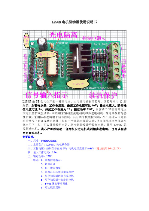
L298N电机驱动器使用说明书L298N是ST公司生产的一种高电压、大电流电机驱动芯片。
该芯片采用15脚封装。
主要特点是:工作电压高,最高工作电压可达46V;输出电流大,瞬间峰值电流可达3A,持续工作电流为2A;额定功率25W。
内含两个H桥的高电压大电流全桥式驱动器,可以用来驱动直流电动机和步进电动机、继电器线圈等感性负载;采用标准逻辑电平信号控制;具有两个使能控制端,在不受输入信号影响的情况下允许或禁止器件工作有一个逻辑电源输入端,使内部逻辑电路部分在低电压下工作;可以外接检测电阻,将变化量反馈给控制电路。
使用L298N芯片驱动电机,该芯片可以驱动一台两相步进电机或四相步进电机,也可以驱动两台直流电机。
简要说明:一、尺寸:80mmX45mm二、主要芯片:L298N、光电耦合器三、工作电压:控制信号直流5V;电机电压直流3V~46V(建议使用36伏以下)四、最大工作电流:2.5A五、额定功率:25W特点:1、具有信号指示。
2、转速可调3、抗干扰能力强4、具有过电压和过电流保护5、可单独控制两台直流电机6、可单独控制一台步进电机7、PWM脉宽平滑调速8、可实现正反转9、采用光电隔离六、有详细使用说明书七、提供相关软件八、提供例程及其学习资料实例一:步进电机的控制实例步进电机是数字控制电机,它将脉冲信号转变成角位移,即给一个脉冲信号,步进电机就转动一个角度,因此非常适合于单片机控制。
步进电机可分为反应式步进电机(简称VR)、永磁式步进电机(简称PM)和混合式步进电机(简称HB)。
一、步进电机最大特点是:1、它是通过输入脉冲信号来进行控制的。
2、电机的总转动角度由输入脉冲数决定。
3、电机的转速由脉冲信号频率决定。
二、步进电机的驱动电路根据控制信号工作,控制信号由单片机产生。
(或者其他信号源)三、基本原理作用如下:两相四拍工作模式时序图:(1)控制换相顺序1、通电换相这一过程称为脉冲分配。
例如:1、两相四线步进电机的四拍工作方式,其各相通电顺序为(A-B-A ’-B ’)通电控制脉冲必须严格按照这一顺序分别控制A,B 相的通断。
BTS7960大功率直流电机驱动器设计原理图pcb图及例程

2、转速可调 3、抗干扰能力强输入全光电隔离 4、内部具有续流保护 5、可单独控制一台直流电机 6、PWM 脉宽平滑调速(可使用 PWM 信号对直流电机调速) 7、可实现正反转 8、此驱动器非常适合控制飞思卡尔智能车,驱动器压降小,电流大,驱动 能力强
适用场合:单片机学习、电子竞赛、产品开发、毕业设计。。。。。。
主函数 *********************************************************************/ main() {
while(1) { if(P2_0==0){delay(3);if(P2_0==0)//启动 { P1_0=0; }} if(P2_1==0){delay(3);if(P2_1==0)//停止 { P1_0=1; }}
人生有几件绝对不能失去的东西:自制的力量,冷静的头脑,希望和信心
14
部分文档来自网络收集,如有侵权,请联系作者删除
14
人生有几件绝对不能失去的东西:自制的力量,冷静的头脑,希望和信心
15
部分文档来自网络收集,如有侵权,请联系作者删除
15
部分文档来自网络收集,如有侵权,请联系作者删除
电机驱动器IC控制电机运转

电机驱动器IC控制电机运转电机驱动器IC控制电机运转随着科技的不断进步和发展,电机驱动技术在各行各业中起到了至关重要的作用。
而电机驱动器IC作为其中的核心部件,扮演着控制电机运转的关键角色。
本文将介绍电机驱动器IC的工作原理、应用领域及前景,并探讨其对电机运转的影响。
一、电机驱动器IC的工作原理电机驱动器IC是一种集成了电机控制电路的芯片,通过接收外部的控制信号来控制电机的运转。
其主要包括输入端、输出端、电源端及控制逻辑电路。
当输入端接收到外部的指令时,控制逻辑电路会相应地处理这些信号,并将输出信号发送到输出端。
这些输出信号可以通过适配器或传感器接口来实现与电机的连接,从而实现对电机运转的控制。
二、电机驱动器IC的应用领域电机驱动器IC广泛应用于各个领域,如工业自动化、汽车行业、电子设备等。
在工业自动化领域,电机驱动器IC可用于控制传送带、机械臂等设备的运转。
在汽车行业中,电机驱动器IC可用于控制车辆的电动座椅、电动车窗等系统。
在电子设备方面,电机驱动器IC可以用于控制风扇、光驱等电机的运转。
三、电机驱动器IC在电机运转中的影响电机驱动器IC在电机运转中发挥了至关重要的作用,它能够提供稳定的控制信号,并保证电机的正常运转。
其控制精度可以影响到电机的速度、扭矩以及转速的调节范围。
此外,电机驱动器IC的效率也会对电机的运行效果产生影响。
高效率的电机驱动器IC可以降低能耗,提高电机的使用寿命。
因此,在选择电机驱动器IC时,需要根据电机的应用需求和要求来进行选择。
四、电机驱动器IC的发展前景随着电机驱动器IC技术的不断发展,其在各个领域中的应用也将不断扩大。
尤其是在工业自动化领域,电机驱动器IC可以提高生产线自动化程度,提高生产效率和质量。
在新能源汽车领域,电机驱动器IC可以提高电动汽车的续航里程和驾驶性能。
因此,电机驱动器IC有着广阔的发展前景。
综上所述,电机驱动器IC作为控制电机运转的关键部件,其工作原理、应用领域及前景都具有重要意义。
大功率IGBT驱动芯片2SD315的应用
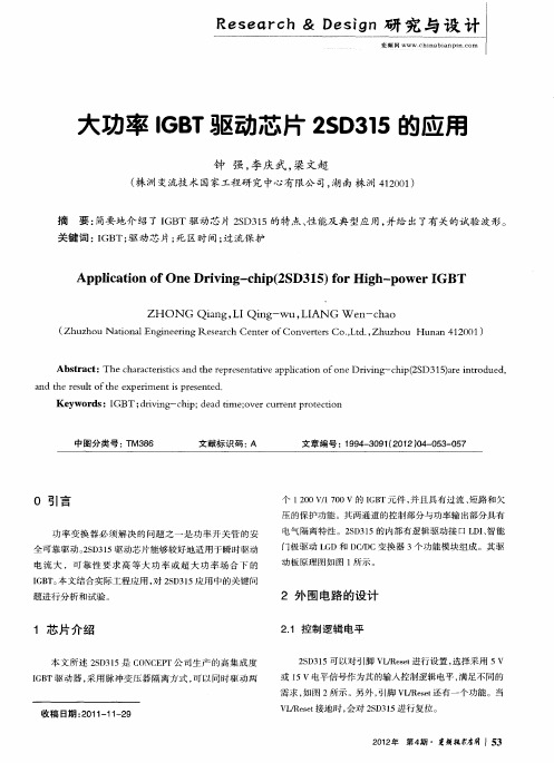
1 芯 片 介 绍
本文所述 2 D 1 S 3 5是 C N E F 司生产 的高集 成度 O CF 公 IB G T驱 动器 , 用脉冲变压器 隔离方式 , 以同时驱 动两 采 可
或 1 5v电平信号作为其的输入控制逻辑电平 , 满足不同的
需 求 , 图 2所示 。另外 , 如 引脚 VJ ee还 有 一 个 功 能 。当 lR st
Ab t a t Th h rcei is n erp ee tt eapiaino o eDr ig hp 2 D3 5aeito u d sr c : ec aa tr t dt rsn a v p l t f n i n —c i(S 1 )r r d e , sc a h e i c o v n
R sac e e r D g h& e in研 究 与 设 计 s
变频 网 WWW.hi a i n i . o c n b a p n c m
大功率 IB 驱动芯 片 2 D 1 GT S 35的应用
钟 强, 李庆武 , 梁文超
( 洲 变流技 术 国 家工程研 究 中心有 限公 司, 南 株 洲 4 2 0 ) 株 湖 10 1
E0 v 4 S I L T 1
V R豢 I T 1 圆 I O D H E
1 2
M1 4 一v
n =MC l =1 0F 1 — J 3
l
s ll 【 1 1
“
; 02
0P F
q
S O l
S O2
、
]
: 。
H
lD 3D C } (
DC  ̄
CM O
——] : 『l 一- C M2 噜] 。“
Ml —R2 El
电机驱动芯片的典型应用

电机驱动芯片的典型应用
电机驱动芯片是一种集成有CMOS控制电路和DMOS功率器件的芯片,主要用于驱动电机,并具备过流、过热等保护功能。
以下是电机驱动芯片的典型应用:
1. 电动工具:利用电机驱动芯片实现调速,以适应不同的工作场景。
芯片通过PWM技术调节电机,实现精细调节,确保电机在不同环境下均表现出色。
2. 机器人:依赖电机驱动芯片实现高精度控制。
电机种类包括直流、步进、伺服等,其控制需要精细调节。
电机驱动芯片能满足这种高要求,广泛用于电动工具、商用及消费性多轴飞行器等。
3. 汽车电子:这是电机驱动芯片的主要应用之一。
涵盖多种电机,如发电机、电动座椅电机等,其控制需精准、可靠。
4. 控制系统:如数字控制系统和电脑打印机与绘图仪,这些都需要用到电机驱动芯片来驱动直流电机、步进电机和继电器等感性负载。
5. 电流控制:电机驱动芯片能够自动调整工作电流,从而优化效率和降低能耗。
其功能强大,可适应各种实际负载情况,提供多种工作模式,并易于与各种控制系统连接。
如需更多关于电机驱动芯片的信息,建议咨询专业人士或查阅相关文献资料。
大功率的MOSFET和IGBT驱动芯片

关键词:IGBT;驱动与保护;IXDN404引言绝缘栅晶体管IGBT是近年来发展最快而且很有前途的一种复合型器件,并以其综合性能优势在开关电源、UPS、逆变器、变频器、交流伺服系统、DC/DC变换、焊接电源、感应加热装置、家用电器等领域得到了广泛应用。
然而,在其使用过程中,发现了不少影响其应用的问题,其中之一就是IGBT的门极驱动与保护。
目前国内使用较多的有富士公司生产的EXB系列,三菱公司生产的M579系列,MOTOROLA公司生产的MC33153等驱动电路。
这些驱动电路各有特点,均可实现IGBT的驱动与保护,但也有其应用限制,例如:驱动功率低,延迟时间长,保护电路不完善,应用频率限制等。
本文,以IXYS公司生产的IGBT驱动芯片IXDN404为基础,介绍了其特性和参数,设计了实际驱动与保护电路,经过实验验证,可满足IGBT的实际驱动和过流及短路时实施慢关断策略的保护要求。
1 IXDN404驱动芯片简介IXDN404为IXYS公司生产的高速CMOS电平IGBT/MOSFET驱动器,其特性如下:--高输出峰值电流可达到4A;--工作电压范围4.5V~25V;--驱动电容1800pF<15ns;--低传输延迟时间;--上升与下降时间匹配;--输出高阻抗;--输入电流低;--每片含有两路驱动;--输入可为TTL或CMOS电平。
其电路原理图如图1所示,主要电气参数如表1所列。
表1 IXDN404主要电气参数符号参数测试条件最小值典型值最大值单位Vih输入门限电压,逻辑1空 3.5空空 VVil输入门限电压,逻辑0 空空空 0.8VVoh输出电压,逻辑1空 Vcc-0.025空空 VVol输出电压,逻辑0空空空0.025VIpeak峰值输出电流Vcc=18V4空空 AIdc连续输出电流Vce=18V空空 1Atr上升时间C1=1800pF Vcc=18V111215ns tf下降时间C1=1800pF Vcc=18V121417ns tond上升时间延迟C1=1800pF Vcc=18V333438ns toffd下降时间延迟C1=1800pF Vcc=18V283035ns Vcc供电电压空 4.51825VIcc供电电流Vin=+Vcc空空10μA2 驱动芯片应用与改进图2为IXDN404组成的IGBT实用驱动与保护电路,该电路可驱动1200V/100A的IGBT,驱动电路信号延迟时间不超过150ns,所以开关频率图2由IXDN404组成的IGBT保护与驱动电路图1IXDN404电路原理图可以高达100kHz。
电机驱动芯片LMD18200原理及应用
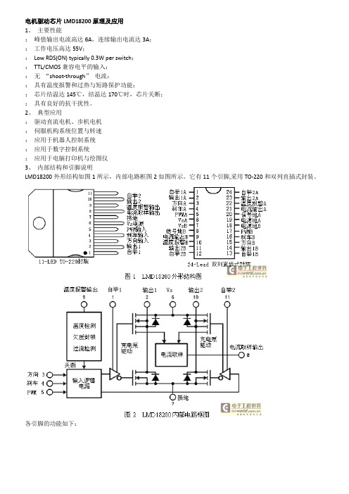
电机驱动芯片LMD18200原理及应用1、主要性能:峰值输出电流高达6A,连续输出电流达3A;:工作电压高达55V;:Low RDS(ON) typically 0.3W per switch;:TTL/CMOS兼容电平的输入;:无“shoot-through”电流;:具有温度报警和过热与短路保护功能;:芯片结温达145℃,结温达170℃时,芯片关断;:具有良好的抗干扰性。
2、典型应用:驱动直流电机、步机电机:伺服机构系统位置与转速:应用于机器人控制系统:应用于数字控制系统:应用于电脑打印机与绘图仪3、内部结构和引脚说明LMD18200外形结构如图1所示,内部电路框图2如图所示。
它有11个引脚,采用TO-220和双列直插式封装。
各引脚的功能如下:引脚名称功能描述LMD18200工作原理:内部集成了四个DMOS管,组成一个标准的H型驱动桥。
通过充电泵电路为上桥臂的2个开关管提供栅极控制电压,充电泵电路由一个300kHz左右的工作频率。
可在引脚1、11外接电容形成第二个充电泵电路,外接电容越大,向开关管栅极输入的电容充电速度越快,电压上升的时间越短,工作频率可以更高。
引脚2、10接直流电机电枢,正转时电流的方向应该从引脚步到引脚10;反转时电流的方向应该从引脚10到引脚2。
电流检测输出引脚8可以接一个对地电阻,通过电阻来输出过流情况。
内部保护电路设置的过电流阈值为10A,当超过该值时会自动封锁输出,并周期性的自动恢复输出。
如果过电流持续时间较长,过热保护将关闭整个输出。
过热信号还可通过引脚9输出,当结温达到145度时引脚9有输出信号。
4、典型应用LMD18200典型应用电路如图3所示。
LMD18200提供双极性驱动方式和单极性驱动方式。
双极性驱动是指在一个PWM周期里,电动机电枢的电压极性呈正负变化。
双极性可逆系统虽然有低速运行平稳性的优点,但也存在着电流波动大,功率损耗较大的缺点,尤其是必须增加死区来避免开关管直通的危险,限制了开关频率的提高,因此只用于中小功率直流电动机的控制。
drv8311 例子

drv8311 例子
DRV8311是一种三相电机驱动器芯片,常用于控制直流电机或
步进电机。
它集成了功率MOSFET驱动器和电流检测器,能够提供高
效的电机控制和保护功能。
以下是一个简单的使用DRV8311的例子:
假设我们要控制一个三相无刷直流电机,我们可以将DRV8311
芯片连接到微控制器和电机的电源供应上。
首先,我们需要配置微
控制器来发送PWM信号给DRV8311,以控制电机的转速和方向。
接着,我们需要连接电机的三个相线到DRV8311的输出引脚,并连接
电机的传感器信号到DRV8311的输入引脚,这样DRV8311就能够感
知电机的转速和位置。
最后,我们可以编写控制算法,通过微控制
器发送适当的PWM信号和控制命令给DRV8311,从而实现对电机的
精确控制。
除了上述基本的连接和控制步骤,使用DRV8311还涉及到一些
额外的功能和保护特性,比如过流保护、过温保护、欠压锁存等。
在实际应用中,我们还需要考虑电机的负载特性、动态响应、噪声
和EMI等问题,以及如何优化控制算法来实现更好的性能和效率。
总之,DRV8311作为一种电机驱动器芯片,在控制电机时需要
综合考虑硬件连接、控制算法、保护机制等多个方面,以实现对电机的稳定、高效、安全的控制。
- 1、下载文档前请自行甄别文档内容的完整性,平台不提供额外的编辑、内容补充、找答案等附加服务。
- 2、"仅部分预览"的文档,不可在线预览部分如存在完整性等问题,可反馈申请退款(可完整预览的文档不适用该条件!)。
- 3、如文档侵犯您的权益,请联系客服反馈,我们会尽快为您处理(人工客服工作时间:9:00-18:30)。
AN1794Application notePractiSPIN evaluation systemconfiguration and set up guideIntroductionPractiSPIN is an evaluation and demonstration system that can be used with severalSTMicroelectronics motor driver integrated circuit devices. The system consists of aGraphical User Interface (GUI) program which runs on an IBM-PC under windows, acommon ST7 based interface board that communicates with the PC and the practiSPINsoftware via a serial COMM port, and a device specific evaluation or target board thatconnects to the ST7 interface board via a standard 34 pin ribbon cable interface, as shownin Figure1. The target PCB connects to the motor or motors and to a user supplied DCpower supply generally in the range of 12 to 48 Vdc.The practiSPIN system is designed to operate the device being evaluated (the target device)under control of the practiSPIN software. Depending on which target device is being used,the practiSPIN software can operate the device to drive a stepper motor, 1 or 2 DC motorsor a brushless DC (BLDC) motor.Figure 1.System block diagramJanuary 2008 Rev 21/34Contents AN1794Contents1System overview . . . . . . . . . . . . . . . . . . . . . . . . . . . . . . . . . . . . . . . . . . . . 51.1Target board . . . . . . . . . . . . . . . . . . . . . . . . . . . . . . . . . . . . . . . . . . . . . . . . 51.2Control interface board . . . . . . . . . . . . . . . . . . . . . . . . . . . . . . . . . . . . . . . . 5 2Starting practiSPIN . . . . . . . . . . . . . . . . . . . . . . . . . . . . . . . . . . . . . . . . . . 73Stepper motor drive . . . . . . . . . . . . . . . . . . . . . . . . . . . . . . . . . . . . . . . . . 83.1Constant speed mode . . . . . . . . . . . . . . . . . . . . . . . . . . . . . . . . . . . . . . . . 83.2Indexing mode . . . . . . . . . . . . . . . . . . . . . . . . . . . . . . . . . . . . . . . . . . . . . . 94DC motor drive . . . . . . . . . . . . . . . . . . . . . . . . . . . . . . . . . . . . . . . . . . . . 104.1Dual DC motor control mode . . . . . . . . . . . . . . . . . . . . . . . . . . . . . . . . . . 105BLDC motor drive . . . . . . . . . . . . . . . . . . . . . . . . . . . . . . . . . . . . . . . . . . 115.1BLDC motor control mode . . . . . . . . . . . . . . . . . . . . . . . . . . . . . . . . . . . . 116EVAL6205N board configuration . . . . . . . . . . . . . . . . . . . . . . . . . . . . . . 126.1Vref offset adjustment (R18) . . . . . . . . . . . . . . . . . . . . . . . . . . . . . . . . . . 146.2Current scaling . . . . . . . . . . . . . . . . . . . . . . . . . . . . . . . . . . . . . . . . . . . . . 147EVAL6206N board configuration . . . . . . . . . . . . . . . . . . . . . . . . . . . . . . 157.1Vref offset adjustment (R18) . . . . . . . . . . . . . . . . . . . . . . . . . . . . . . . . . . 177.2Current scaling . . . . . . . . . . . . . . . . . . . . . . . . . . . . . . . . . . . . . . . . . . . . . 178EVAL6206PD board configuration . . . . . . . . . . . . . . . . . . . . . . . . . . . . . 188.1Vref offset adjustment (R18) . . . . . . . . . . . . . . . . . . . . . . . . . . . . . . . . . . 208.2Current scaling . . . . . . . . . . . . . . . . . . . . . . . . . . . . . . . . . . . . . . . . . . . . . 209EVAL6207N board configuration . . . . . . . . . . . . . . . . . . . . . . . . . . . . . . 219.1Vref offset adjustment (R18) . . . . . . . . . . . . . . . . . . . . . . . . . . . . . . . . . . 239.2Current scaling . . . . . . . . . . . . . . . . . . . . . . . . . . . . . . . . . . . . . . . . . . . . . 2310EVAL6208N board configuration . . . . . . . . . . . . . . . . . . . . . . . . . . . . . . 2410.1Vref offset adjustment (R18) . . . . . . . . . . . . . . . . . . . . . . . . . . . . . . . . . . 26 2/34AN1794Contents10.2Current scaling . . . . . . . . . . . . . . . . . . . . . . . . . . . . . . . . . . . . . . . . . . . . . 2611EVAL6208PD board configuration . . . . . . . . . . . . . . . . . . . . . . . . . . . . . 2711.1Vref offset adjustment (R18) . . . . . . . . . . . . . . . . . . . . . . . . . . . . . . . . . . 2911.2Current scaling . . . . . . . . . . . . . . . . . . . . . . . . . . . . . . . . . . . . . . . . . . . . . 2912EVAL6235 board configuration . . . . . . . . . . . . . . . . . . . . . . . . . . . . . . . 3012.1Vref offset adjustment (R18) . . . . . . . . . . . . . . . . . . . . . . . . . . . . . . . . . . 3212.2Current scaling . . . . . . . . . . . . . . . . . . . . . . . . . . . . . . . . . . . . . . . . . . . . . 32 13Revision history . . . . . . . . . . . . . . . . . . . . . . . . . . . . . . . . . . . . . . . . . . . 333/34List of figures AN1794 List of figuresFigure 1.System block diagram . . . . . . . . . . . . . . . . . . . . . . . . . . . . . . . . . . . . . . . . . . . . . . . . . . . . . 1 Figure 2.ST7 interface board . . . . . . . . . . . . . . . . . . . . . . . . . . . . . . . . . . . . . . . . . . . . . . . . . . . . . . . 6 Figure 3.EVAL6205N schematic. . . . . . . . . . . . . . . . . . . . . . . . . . . . . . . . . . . . . . . . . . . . . . . . . . . . 13 Figure 4.EVAL6206 schematic. . . . . . . . . . . . . . . . . . . . . . . . . . . . . . . . . . . . . . . . . . . . . . . . . . . . . 16 Figure 5.EVAL6206PD schematic . . . . . . . . . . . . . . . . . . . . . . . . . . . . . . . . . . . . . . . . . . . . . . . . . . 19 Figure 6.EVAL6207N schematic. . . . . . . . . . . . . . . . . . . . . . . . . . . . . . . . . . . . . . . . . . . . . . . . . . . . 22 Figure 7.EVAL6208N schematic. . . . . . . . . . . . . . . . . . . . . . . . . . . . . . . . . . . . . . . . . . . . . . . . . . . . 25 Figure 8.EVAL6208PD schematic . . . . . . . . . . . . . . . . . . . . . . . . . . . . . . . . . . . . . . . . . . . . . . . . . . 28 Figure 9.EVAL6235 schematic. . . . . . . . . . . . . . . . . . . . . . . . . . . . . . . . . . . . . . . . . . . . . . . . . . . . . 31 4/34AN1794System overview 5/341 System overviewTo illustrate the operation of the practiSPIN system, we will look at one typical devicesupported by the system.The L6207 includes two independent full or H bridges with separate logic inputs and currentcontrol functions.The two bridges are designated A and B and their output pins designated as OUT1A,OUT2A, OUT1B, and OUT2B. These outputs are controlled independently by logic inputsIN1A, IN2A, IN1B, and IN2B respectively.A logic high or low on any of these inputs will drive its corresponding output to the positivesupply rail or to ground. Both of the A outputs will be forced to an off (high impedance) stateif the ENA pin is taken logic low, as will the B outputs if ENB is taken low. The L6207 is thuscontrolled by six logic inputs: IN1A, IN2A, and ENA controlling bridge A and IN1B, IN2B, andENB controlling bridge B. Each bridge also has an analog control signal, VREFA andVREFB, which control the current.1.1 Target boardThe L6207 target board gives access to the bridge A and B outputs at connectors CN3 andCN4 respectively.When driving a stepper motor, the two wires from one of the motor windings will connect toCN3 and the other winding will connect to CN4. Swapping between the two connectors orswapping the polarity at a given connector will only reverse the sense of motor direction. DCsupply power in the range of 12 to 48 Vdc is connected at CN1. The polarity marked on theboard silkscreen must be strictly observed! The eight control signals are taken from the 34-pin ribbon header (CN5) and are driven by the control interface PCB via a short flat cable.1.2 Control interface boardThe control interface PCB is based on an ST72F264 microcontroller. The micro includes aUART and communicates with the practiSPIN software via 9 pin D connector P1 employinga standard RS232 interface.The micro is based on flash memory and its firmware includes a write protected boot-loaderroutine that allows the practiSPIN software to update or change the operating program in theST7 as required for different target boards. 5 Vdc power for the board is received via the 34-pin ribbon cable from the target board or can be directly supplied at J2 if jumper WJ1 isremoved. The eight control signals for the target board are generated by the ST7 micro. Thesix logic signals are generated directly by six of the eight pins of port B while the two analogcurrent references (VREFA and VREFB) are generated by pulse width modulated (PWM)signals generated by the ST7 along with an offset adjusting circuit controlled bypotentiometer R18.System overview AN17946/34Figure 2.ST7 interface boardAN1794Starting practiSPIN 7/342 Starting practiSPINSince the practiSPIN system is capable of supporting several driver IC's and driving differenttypes of motors the user must first select the type of motor to be driven and the driver IC thatwill be evaluated.1.Target board set up: configure the jumpers/switches on the target board and the ST7interface board as described in the paragraph for the specific evaluation board beingused.2. Control board - PC connection: connect the ST7 interface board to a serial COMM portof the PC via a standard (straight through) 9 pin D connector cable.3. Power up: energize the power supply.4. Start practiSPIN software: on the PC, start the practiSPIN program.5. Motor type selection: on the first screen of the practiSPIN software, the user can selectthe appropriate type of motor for the device under evaluation. Click on the appropriatemotor type.6. Communication settings: click the drop down list under "port selection" and select theCOMM port being used. Baud rate and other communication parameters are fixed onboth sides of the link and do not need to be set.7. Establish COMM link: click the "Connect With ST7 Hardware". At this point thepractiSPIN software will transmit several commands to the ST7 to initialize theprocessor. The practiSPIN software will read the revision code of the firmware currentlystored in the flash memory of the ST7 and determine if the correct version of firmwareresides in the ST7. If the practiSPIN software detects that a firmware update isnecessary, either because there is an old version of firmware or the firmware currentlyin the flash memory is not the correct firmware for the motor type selected, one or moredialogue boxes will appear asking if the program should proceed with the update.Accept the updates and the practiSPIN software will automatically update the firmware.The system will then initialize the settings to the last stored settings and open theappropriate practiSPIN software for the selected motor type.8.Calibrate current setting: when communication is established the user has the option toadjust the offset and maximum current settings. If this is the first time you use thesystem, calibration may be needed to adjust out the offset in the reference biascircuitry. Calibration ensures that the reference voltage provided to L62XX IC followsthe practiSPIN software current settings. Calibration is a two-step process; first theoffset is adjusted then the maximum current is set.a) To null out the offset, click on CALIBRATE ZERO then adjust R18 (on ST7 board)until voltage at Vref pin(s) of the L62XX device is zero. Measurement points oneach board are listed in the set up section for each target board.b) The maximum current, corresponding to 100% current setting in the practiSPINsoftware, can be adjusted using the Vref potentiometers on the target board. If thepotentiometers are set to full scale (clockwise) the reference applied to the input ofthe device is typically about 0.88 V . The full-scale peak current is equal toVref/Rsense where Rsense is the composite value of the sense resistor on theboard. To set the maximum current, click on CALIBRATE MAX and trim the Vrefpotentiometer(s) on the EVAL62XX board to set the desired reference. If you planto use microstepping, consider reducing the maximum Vref to the real peak valueyou will use, allowing setting the software current controls near to 100%, avoidingpoor Vref resolution.Stepper motor drive AN1794 3 Stepper motor driveAfter the system has established the connection to the interface board, it will initialize thesettings to the last stored settings and open the appropriate GUI for the selected motor type.For the Stepper motor, the system can operate in either a constant speed or positioning(indexing) mode. The constant speed mode can easily be used to see that the system isworking.3.1 Constant speed mode1.Speed control screen: a large blue button at the bottom of the screen should read,"switch to INDEXING MODE". If the button reads, "switch to SPEED CONTROLMODE", click the button once to go to speed control mode.2. Stepping mode: in the stepping mode box, select either Normal or Half Step.Microstepping mode is only available when using the L6208.3. Device selection: in the device selection box, select the device being evaluated.4. direction: in the direction box, click the toggle switch to pick forward or reverse. This issomewhat arbitrary since we probably don't know what the direction sense of the motorwill be. Once the motor is running, toggle this switch to reverse the motor direction ifdesired. To reverse the meaning of the forward and reverse designations, disable themotor (orange disable button at bottom of screen) and then swap the motor wires ateither CN3 or CN4.5. Decay mode: only the L6208 allows the selection of fast or slow decay. Set the toggleswitch to slow decay.6. Accel rate: set the accel rate to about 1000 steps per second per second (steps/sec2).In the practiSPIN system all motion parameters are given in terms of the basic units ofsteps and seconds: position in steps, velocity in steps/sec, and accel/decel insteps/sec2. In order to relate these settings to rotations, RPM, and RPM/second it isnecessary to know the number of steps (or half steps) per rotation for the stepper motorbeing used. A common value is 200 steps or 400 half steps per rotation.7. Running speed: set running speed to about 100 steps/sec.8. Decel rate: set decel. rate to about 1000 steps/sec2.9. Accel current: set accel current to about 25%. This is an initial guess as to the requiredsetting and may need further adjustment. Generally higher accel rate settings requirehigher accel current settings so that the stepper motor does not start to "slip poles" andfall behind the desired position. Since we have initially set the acceleration rate settingquite low, 25% is probably adequate.10. Running current: set the running current to 25%. In practice the running current canoften be set to a lower value than the accel current since the torque requirement isgenerally less during the constant speed part of the move. A lower running currentsetting can help to keep the device and the motor running cooler.11. Decel current: set the decel current to 25%. Since friction aids in decelerating the motorit may also be possible to set the decel current lower.12. Holding current: set the holding current to 25%. Whenever the motor is stopped (after arun,) this level of current will circulate in the motor so that it will hold position againstany mechanical disturbance.8/34AN1794Stepper motor drive9/34In the case of a strong static load (perhaps a gravity load of some sort) it may be necessaryto increase this setting. If not much holding torque is required, then the setting can bereduced so that operating temperatures can be held to a minimum.Note:Holding current will be turned off (bridge completely disabled) whenever the disable buttonis clicked.13. Run: make sure that the motor is free to turn in either direction and click the run button.The motor should quickly come up to speed ((100 steps/sec) / (1000 steps/sec2) = 0.1sec.). To change the motor direction, click the direction toggle switch. If the motor doesnot run click the stop button, increase all four current settings to 50%, and click runbutton. If the motor still does not run an oscilloscope and current probe should be usedto observe the motor current.14. Stop: click stop to stop the motor.After the basic operation of the system has been verified, the acceleration rates, top speed,and current settings can be adjusted to see how the motor responds.3.2 Indexing modeThe system can be switched to operate in the positioning (indexing) mode by clicking on"switch to INDEXING MODE". In the indexing mode a new box appears on the right of thescreen. Y ou can enter up to twelve indexed movements in the box and the wait time betweeneach movement. When started, the software will execute each movement by accelerating upto the peak speed, moving the required number of steps and then decelerating back to astop so that the total distance moved is the number of steps indicated, then wait theindicated time before starting the next movement. A negative number entered in the relativeposition will cause the motor to run in the "reverse" direction.DC motor drive AN1794 4 DC motor driveAfter the system has established the connection to the interface board, it will initialize thesettings to the last stored settings and open the appropriate practiSPIN software for theselected motor type. For DC motor drive, the system operates in an open loop duty cyclecontrol mode with cycle-by-cycle current limit.4.1 Dual DC motor control mode1.Direction: in the direction box for each motor, click the toggle switch to pick forward orreverse. This is somewhat arbitrary since we probably don't know what the directionsense of the motor will be. Once the motor is running, toggle this switch to reverse themotor direction if desired. To reverse the meaning of the forward and reversedesignations, disable the motor (orange disable button at bottom of screen) and thenswap the motor wires at either CN3 or CN4.2. Braking: toggle the "Brake when Stop" switch to the OFF position for both motors. Thiswill cause the motor to coast to rest when stopped, with the bridge placed in a highimpedance state. If desired this function can later be toggled on but some care shouldbe exercised. Braking will effectively short out the motor armature through twotransistors in the bridge, which could cause excessive current and power dissipation ifthe motor and load have a large moment of inertia (thus a large amount or storedmechanical to be dissipated) or the motor has a very low resistance (resulting in a largecurrent flow). Most smaller DC motors with several ohms of resistance do not pose arisk.3. Current: set the current for both motors to approximately 25%. This is an initial guessas to the required setting and may need further adjustment.4. Voltage: set the voltage for both motors to approximately 50%.5. Run: make sure that the motors are free to turn in either direction and click the runbutton. the motors should come up to approximately half of the speed that would beexpected at this supply voltage. To change the motor direction, click the direction toggleswitch. If the motors do not run click the STOP button, increase both current settings to50%, and click RUN button. If the motors still do not run an oscilloscope and currentprobe should be used to observe the motor current6. Stop: click stop to stop the motor.After the basic operation of the system has been verified, adjust voltage, current, directionand other parameters to evaluate the system.10/34AN1794BLDC motor drive 5 BLDC motor driveAfter the system has established the connection to the interface board, it will initialize thesettings to the last stored settings and open the appropriate practiSPIN software for theselected motor type. For BLDC motor drive, the system operates in an open loop duty cyclecontrol mode with cycle-by-cycle current limit.5.1 BLDC motor control mode1.Direction: in the direction box for each motor, click the toggle switch to pick forward orreverse. This is somewhat arbitrary since we probably don't know what the directionsense of the motor will be. Once the motor is running, toggle this switch to reverse themotor direction if desired.2. Braking: toggle the "Brake when Stop" switch to the OFF position. This will cause themotor to coast to rest when stopped, with the bridge placed in a high impedance state.If desired this function can later be toggled on but some care should be exercised.Braking will effectively short out the motor armature through three transistors in thebridge, which could cause excessive current and power dissipation if the motor andload have a large moment of inertia (thus a large amount or stored mechanical to bedissipated) or the motor has a very low resistance (resulting in a large current flow).Most smaller BLDC motors with several ohms of resistance do not pose a risk.3. Current: set the current to approximately 25%. This is an initial guess as to the requiredsetting and may need further adjustment.4. Voltage: set the voltage to approximately 50%.5. Run: make sure that the motor is free to turn in either direction and click the run button.The motor should come up to approximately half of the speed that would be expectedat this supply voltage. To change the motor direction, click the direction toggle switch. Ifthe motor does not run click the stop button, increase the current settings to 50%, andclick run button. If the motor still does not run an oscilloscope and current probe shouldbe used to observe the motor current.6. Stop: click stop to stop the motor.After the basic operation of the system has been verified, adjust voltage, current, directionand other parameters to evaluate the system.11/34configurationboard6 EVAL6205NThe schematic of the EVAL6205N board is shown in Figure3. To use the EVAL6205N boardwith practiSPIN system, the following configuration settings must be made on theEVAL6205N:ponent updates: depending on the revision of the board, some or all of thefollowing changes may be required (or desirable):a) To assure safe overcurrent operation: change C6 and C7 to 5.6 nF Change R5and R6 to 100 kΩ.b) To assure an adequate 5 V supply, R2 may need to be changed. The minimumvalue for R2 is (Vs-5)/(0.03+I) Ω . Where: Vs is the supply voltage and I is anyadditional load placed on the 5 V supply (in amps).2. JP1: place JP1 in the INT position to enable the on-board 5 Vdc supply.3. JP2 and JP3: install JP2 and JP3 to assure proper timing operation of the L6205'sinternal high side overcurrent protection.4. JP4 and JP5: install JP4 and JP5 to configure the Vref circuits.5. R17 & R21: adjust multi-turn trim potentiometers R17 and R21 fully clockwise. Note: A slight click can be heard from the pot when it reaches its end of travel.6. R23 Adjust multi-turn trim pot R23 to the middle of its range. This pot sets thefrequency of the cycle-bycycle current controller and can be fine tuned while observingthe motor current on an oscilloscope or by simply adjusting to raise the frequency of theaudible switching noise to an inaudible level if required.7. Motor connections: connect the motor coils at CN3 and CN4. When driving a steppermotor, one winding is connected to CN3 and the second winding is connected to CN4.For operation with 2 DC motors one motor is connected to each connector.8. Power supply: connect, but do not energize, a 12 to 48 Vdc power supply at CN1(positive to V in and negative to GND).9. Using a 34 pin ribbon cable connect the EVAL6205N board to the control interfaceboard. The two boards should be placed on the bench so that their 34 pin headers areside by side with the ribbon cable going straight across. Set the following on the ST7interface board.10. WJ1: install WJ1 on the ST7 based control interface board. This allows 5 Vdc power tobe obtained from the target board.11. JP1 and JP2 and R18: install the JP1 and JP2 jumpers to short the center and left pinstogether as shown in Figure2. This is critical as excessive motor current can resultfrom misplacement of these jumpers! Set potentiometer R18 to about 50%.12/3413/346.1 Vref offset adjustment (R18)Using a voltmeter monitor the voltage at jumper JP4 or JP5 the EVAL6205N board withrespect to GND (CN1) when calibrating the offset.scaling6.2 CurrentWhen potentiometers R17 and R21 are set full clockwise, a 100% current setting on thepractiSPIN software screen corresponds to a Vref of approximately 0.88 Vdc or a peakmotor current of about 2.64 A.The peak current can be set to a lower value by adjusting R17 and R21. The referencevoltage inputs can be monitored at JP4 and JP5.14/34configurationboard7 EVAL6206NThe schematic of the EVAL6206N board is shown in Figure4. To use the EVAL6206N boardwith practiSPIN system, the following configuration settings must be made on theEVAL6206N:ponent updates: depending on the revision of the board, some or all of thefollowing changes may be required (or desirable):a) To assure safe overcurrent operation:–Change C6 and C7 to 5.6 nF–Change R5 and R6 to 100 kΩb) To assure an adequate 5 V supply, R2 may need to be changed. The minimumvalue for R2 is (Vs-5)/(0.03+I) Ω . Where: Vs is the supply voltage and I is anyadditional load placed on the 5 V supply (in amps).2. JP1: place JP1 in the INT position to enable the on-board 5 Vdc supply.3. JP2 and JP3: install JP2 and JP3 to enable the L6206's internal high side overcurrentprotection.4. JP4 and JP5: install JP4 and JP5 to set internal overcurrent threshold to maximum. Ifdesired, these jumpers can be left out and the overcurrent levels may be set usingpotentiometers R7 and R8.5. JP6 and JP7: install JP6 and JP7 to configure the Vref circuits.6. R20 and R26 adjust multi-turn trim pots R20 and R26 fully clockwise.Note: A slight click can be heard from the pot when it reaches its end of travel.7. R29: adjust multi-turn trim pot R29 to the middle of its range. This pot sets the choppingfrequency of the L6506 current controller and can be fine tuned while observing themotor current on an oscilloscope or by simply adjusting to raise the frequency of theaudible switching noise to an inaudible level if required.8. Motor connections: connect the motor coils at CN3 and CN4. When driving a steppermotor, one winding is connected to CN3 and the second winding is connected to CN4.For operation with 2 DC motors one motor is connected to each connector.9. Power supply: connect, but do not energize, a 12 to 48 Vdc power supply at CN1(positive to V in and negative to GND).10. Using a 34 pin ribbon cable connect the EVAL6205N board to the control interfaceboard. The two boards should be placed on the bench so that their 34 pin headers areside by side with the ribbon cable going straight across. Set the following on the ST7interface board.11. WJ1: install WJ1 on the ST7 based Control Interface Board. This allows 5 Vdc power tobe obtained from the target board.12. JP1 and JP2 and R18: install the JP1 and JP2 jumpers to short the center and left pinstogether as shown in Figure2. This is critical as excessive motor current can resultfrom misplacement of these jumpers! Set potentiometer R18 to about 50% .15/34。