基准镇流器使用说明书
NCP5181 36 W镇流器评估板用户手册说明书

NCP5181BAL36WEVB NCP5181 36 W Ballast Evaluation Board User's ManualDescriptionThis document describes how the NCP5181 driver can be implemented in a ballast application. The scope of this evaluation board user’s manual is to highlight the NCP5181driver and not to explain or detail how to build an electronic ballast.The NCP5181 is a high voltage power MOSFET driver providing two outputs for direct drive of two N-channel power MOSFETs arranged in a half-bridge (or any other high-side + low-side topology) configuration.It uses the bootstrap technique to ensure a proper drive of the high-side power switch. The driver works with two independent inputs to accommodate with any topology (including half-bridge, asymmetrical half-bridge, active clamp and full-bridge).Evaluation Board Specification•Input Range: 85−145Vac OR 184−265Vac •Ballast Output Power: 36W (type PL −L 36W)•Pre-heating Current: 295mA •Pre-heating Time: 1second •Nominal Current: 414mADetailed OperationThe lamp ballast is powered via a half bridge configuration. The two power MOSFETs are driven with the NCP5181 driver. The driver is supplied by the V CC rail, and the high side driver is supplied by the bootstrap diode: when the low side power MOSFET (Q2) is switched ON, the BRIDGE pin is pulled down to the ground, thus the capacitor connected between the BRIDGE pin and VBOOT pin is refuelled via the diode D3 and the resistor R5 connected to V CC . When Q2 is switched OFF, the bootstrap capacitor C6supplies the high side driver with a voltage equal to V CC level minus D3 forward voltage diode. Given the NCP5181architecture, it is up to the designer to generate the right input signal polarity. This includes a dead time to avoid a short circuit between the high and low side power MOSFET.The 555 timer generates only one signal for the driver, the second one, in opposite phase is built by inserting an NPN transistor (Q4) for inverting the signal. Afterwards, the dead time is built with R2, D2 and C13 (typically 260ns, see Figure 2).Figure 1. NCP5181 Evaluation BoardWARNING:BEFORE PLUGGING IN THE EVALUATION BOARD, MAKE SURE THE JUMPER IS IN THE CORRECT POSITION: IF J2IS USED, THEN Vin MUST BE LOWER THAN 145Vac.EVAL BOARD USER’S MANUALNCP5181BAL36WEVBDRV_HI (5 V/div)DRV_LO (5 V/div)Time(400 ns/div)Dead time260nsFigure 2. Dead Time Between the High and Low Side DriverIN_HI (10 V/div)DRV_HI (10 V/div)IN_LO(10 V/div)DRV_LO (10 V/div)Time (4 μs/div)Figure 3. Input Output Timing DiagramTube V oltage (100 V /div)Tube current (0.5 V /div)Tube Power (50W/div)TubeAverage power = 32WFigure 4. Tube SignalsNCP5181BAL36WEVBFigure 5. Evaluation Board Schematic720n F 00V820n F 00VFigure 6. PCB Printout: Top and Bottom ViewTEST PROCEDUREFigure 7. Test Setup ConnectionR Load 200 WTable 1. REQUIRED EQUIPMENTAC Power Source can be able to deliver 230V rms or 110V rmsTwo Volt-metersTwo Ampere-meters1 Resistive Load: 200W /50WOne NCP5181 Evaluation Board−Test Procedure1.First of all check if you need jumper #2 (J2 on the board close the diode bridge). This jumper must be removed for use with European mains (230Vac input voltage), and must be in place when using US mains (110Vac). This jumper is used to build a voltage doubler just after the bridge diode in case one is using US mains input voltage range.2.Connect the test setup as shown in Figure 7:•AC Source•V oltmeter and Ampmeter on the Load •Load on the Output3.Apply 230Vac for European mains or 110Vac for US mains on the input connector.4.Check I Load and V Load with the appropriate value in the table below.5.If you get the correct output and input voltage, you can then connect a 36W fluorescent tube on the output (see Figure 8).Table 2. TEST RESULTSInput Mains J2V in (V rms )I in (A rms)V Load (V rms )ILoad (A rms )European Removed230V 278mA 303V 370mA US Yes → Max Input Voltage: 132 V rms110V514mA263V340mAFigure 8. Ballast ConnectionInput ConnectionOutput Connection36W TubeTable 3. BILL OF MATERIAL FOR THE NCP5181 EVALUATION BOARDDesignator Qty.Description Value Tolerance Footprint Manufacturer ManufacturerPart NumberSubstitutionAllowedLeadFreeU21NCP5181NA NA DIP8ON Semiconductor NCP5181PG No Yes U11CMOS IC Analog/Timer NA DIP8Texas Instruments TLC555CP Yes No C1, C22Electrolytic Capacitor47m F, 400V20%Radial Panasonic ECA2GM470Yes No C31Electrolytic Capacitor220m F, 16V20%Radial Panasonic ECA1CM221Yes No C41Electrolytic Capacitor 4.7m F, 63V20%Radial Panasonic EEUEB1J4R7Yes No C5, C62Capacitor100nF, 50V10%Radial Murata RPER71H104K2M1A05U Yes No C7, C82Capacitor220nF, 400V10%Radial Vishay MKT1822422405Yes No C9, C102Capacitor220nF, 100V5%Radial Murata RPE5C2A221J2M1Z05A Yes No C111Capacitor10nF, 100V10%Radial Murata RPER72A103K2M1B05A Yes No C12, C132Capacitor18pF, 100V2%Radial Vishay2252 586 20154Yes Yes C141Capacitor220pF, 400V10%Radial Panasonic ECKATS221KB Yes No C151Capacitor 6.8nF, 1600V5%Radial Vishay2222 375 30682Yes No C161Capacitor NC−Radial−−−−C171Electrolytic Capacitor100m F, 16V20%Radial Panasonic ECA1CM101Yes No D11Zener Diode15V, 1.3W5%Axial Vishay BZX85C15Yes No D21High-speed Diode0.2A, 75V NA Axial PhilipsSemiconductor1N4148Yes No D3, D5, D63Rectifier Diode1A, 400V NA Axial ON Semiconductor1N4936G Yes Yes D41Zener Diode 5.1V, 1.3W5%Axial Vishay BZX85C5V1Yes No F11Fuse500mA, 250V NA Radial Schurter0034.6612Yes No L11Inductor 1.4mH NA NA Vogt53−044No No PT11Diode Bridge600V, 1A NA DFM Vishay DF06M Yes No R11Resistor12k W, 0.33W5%Axial Vishay CFA020712K Yes No R21Resistor82k W, 0.33W5%Axial Vishay CFA020782K Yes No R3, R42Resistor82k W, 3W5%Axial Vishay CPF382K000JN Yes No R5, R6, R73Resistor10W, 0.33W5%Axial Vishay CFA020710R Yes No R8, R92Resistor10k W, 0.33W5%Axial Yageo CFA020710K Yes No R101Resistor33k W, 0.33W5%Axial Vishay CFA020733K Yes No R111Resistor47k W, 0.33W5%Axial Vishay CFA020747K Yes No R121Resistor27k W, 0.33W5%Axial Vishay CFA020727K Yes No R131Resistor15k W, 0.33W5%Axial Vishay CFA020715K Yes No R141Resistor390k W, 0.33W5%Axial Vishay CFA0207390K Yes No R151Resistor22k W, 0.33W5%Axial Vishay CFA020722K Yes No R161Resistor68 k W, 0.33 W5%Axial Vishay CFA020768K Yes NoQ1, Q22Power MOSFETN-channel 8A, 500V NA TO220InternationalRectifierIRF840LC Yes NoQ3, Q42NPN Transistor100mA, 45V NA TO−92ON Semiconductor BC547BG Yes Yes B1, J12Connector2/″NA 5.08mm Weidmuller PM5.08/2/90(1760510000)Yes No J21Jumper Resistor0W, 0.25W NA Axial Yageo ZOR−25−B−52Yes NoADDITIONAL INFORMATIONTECHNICAL PUBLICATIONS :Technical Library: /design/resources/technical−documentation onsemi Website: ONLINE SUPPORT : /supportFor additional information, please contact your local Sales Representative at /support/sales。
1u开关整流器用户手册V1

15A 描述
第 1 章 概述
20A 描述
符合 EN60950 的要求
电池充电电流大于 0.6A,整流器将进入均充,均充电压为 56.4V,当充电 电流大于 3.5A 时,整流器进入限流均充状态,当电池充电电流小于 0.6A 时,整流器将自动转为浮充状态,浮充电压为 53.5V。(24V 时电压减半) 交流断电时,接入电池,如电池电压大于 42.5V,此时整流器内的电池继 电器吸合,电池在线可对负载放电,若电池电压低于 42V,整流器将断掉 电池进行保护。(24V 时电压减半) 整流器不开机时,接入电池,即使电池反接整流器开机也也不会烧毁。如 果整流器在开机状态下接入电池,如电池反接,将会烧毁,严禁开机接入 电池。 平均故障间隔时间 MTBF≥100 000 h 强迫风冷的冷却方式(整流器内部有直流风扇,风通量为 10 CFM)。
第 4 章 使用和维护 4.1 使用………...………………………………………….……………….……..………..10
4.1.1 整流器使用………………………….………………….....................................10 4.1.2 内部保护功能……………………………….…………………...……………..10 4.2 维护………...………………………………………….…………………………….....11 4.2.1 日常维护………...………………………………………….…………………..11 4.2.2 故障处理………...………………………………………….…………………..11
15°C ~+50°C 40°C ~+85°C 10%~90%(无凝露) 高×宽×深:45 mm×282 mm×242 mm(不计输出端子) 3.5 kg YD/T7312002 通信用高频开关整流器
镇流器的一般工作原理

镇流器的一般工作原理和功能、性能及使用条件的简介1 名词解释1.1电光源将电能转换成光学辐射能的器件(有时也用于某些类型的照明器)。
1.2放电灯由气体、金属蒸气或几种气体与金属蒸气的混合放电而发光的灯。
1.3金属蒸气(放电)灯由金属蒸气放电而发光的灯,如汞(蒸气)灯、钠(蒸气)灯等等。
1.4汞(蒸气)灯由汞蒸气放电而发光的灯。
1.5高压汞(蒸气)灯放电稳定时,汞蒸气的分压强达到或大于10000Pa的汞(蒸气)灯。
1.6钠(蒸气)灯主要由钠蒸气放电而发光的灯。
1.7高压钠(蒸气)灯放电稳定时,灯内钠蒸气的分压强达到或大于10000Pa的钠(蒸气)灯。
1.8金属卤化物灯由金属蒸气与金属卤化物分解物的混合物放电而发光的放电灯。
1.9镇流器稳定放电灯放电的器件。
2 放电灯的主要性能及参数名词2.1启动时间接通放电灯的电源开关至灯能开展工作所需的时间。
2.2再启动时间放电灯稳定工作后断开电源,从再次接通电源到灯重新开始启动工作所需的时间。
2.3启动电压放电灯开始持续放电时,电极之间所需的最低电压。
2.4灯电流光源稳定工作时,通过光源灯头触点上的电流。
2.5额定电压灯的设计工作电压(直流或交流的有效值)。
2.6额定电流灯在额定电压下的设计电流。
2.7额定功率灯的设计功率。
3 镇流器3.1镇流器的功能3.1.1将灯的启动电流限制在合适的范围内启动电流是指灯在接通电源启动后的30秒内或灯预热过程中通过灯的电流。
一般情况(尤其在最低温度状态)下,启动电流远大于灯的工作电流,所以每种灯都规定了启动电流的最大值。
如果启动电流过大将会缩短灯的使用寿命:电流过小则不能使灯预热至正常的启动状态或完成由辉光放电向弧光放电过程。
镇流器提供灯的启动电流就应该既能在较短的时间内启动灯,又不至于影响灯的正常使用寿命。
3.1.2提供的开路电压足以使灯顺利的启动镇流器的开路峰值电压作为灯的启动电压时,必须足以电离气体放电灯中的气体,即产生峰值电流使电极之间产生辉光至弧光过度的放电,这样才能使灯启动工作。
STPS20M100S Power Schottky整流器规格书说明书
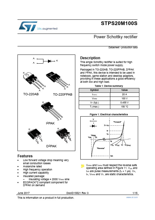
June 2017 DocID15521 Rev 3 1/15This is information on a product in full production.STPS20M100SPower Schottky rectifierDatasheet - production dataFeatures∙ Low forward voltage drop meaning very small conduction losses ∙Avalanche rated∙ High frequency operation ∙ High current capability ∙ Insulated package:- Insulating voltage = 2000 V RMS sine ∙ECOPACK ®2 compliant component for D²PAK on demandDescriptionThis single Schottky rectifier is suited for high frequency switch mode power supply.Packaged in TO-220AB, TO-220FPAB, D²PAK and I²PAK, this device is intended to be used in notebook, game station and desktop adaptors, providing in these applications a good efficiency at both low and high load.Figure 1: Electrical characteristicsV ARM and I ARM must respect the reverse safe operating area defined in Figure 11. V AR and I AR are pulse measurements (t p < 1 μs). V R , I R , V RRM and V F , are static characteristics.Characteristics STPS20M100S1 CharacteristicsTable 2: Absolute ratings (limiting values with terminals 1 and 3 short circuited, at 25 °CNotes:(1)For pulse time duration deratings, refer to Figure 4 . More details regarding the avalanche energymeasurements and diode validation in the avalanche are provided in the application notes AN1768 and AN2025.(2)Refer to Figure 11(3)(dP tot/dT j) < (1/R th(j-a)) condition to avoid thermal runaway for a diode on its own heatsink.STPS20M100S CharacteristicsNotes:(1)Pulse test: t p= 5 ms, δ < 2%(2)Pulse test: t p= 380 µs, δ < 2%To evaluate the conduction losses, use the following equation:P = 0.425 x I F(AV) + 0.0088 x I F2(RMS)Characteristics STPS20M100S 1.1 Characteristics (curves)Package information STPS20M100S2 Package informationIn order to meet environmental requirements, ST offers these devices in different grades ofECOPACK® packages, depending on their level of environmental compliance. ECOPACK®specifications, grade definitions and product status are available at: .ECOPACK® is an ST trademark.∙Cooling method: by conduction (C)∙Epoxy meets UL 94,V0∙Recommended torque value: 0.55 N·m (for TO-220AB and TO-220FPAB)∙Maximum torque value: 0.7 N·m (for TO-220AB and TO-220FPAB)2.1 TO-220AB package informationSTPS20M100S Package informationPackage information STPS20M100S 2.2 TO-220FPAB package informationSTPS20M100S Package informationPackage information STPS20M100S 2.3 I²PAK package informationSTPS20M100SPackage information2.4 D²PAK package informationThis package drawing may slightly differ from the physical package. However, all the specified dimensions are guaranteed.Package information STPS20M100SSTPS20M100S Package informationFigure 16: D²PAK recommended footprint (dimensions in mm)Ordering information STPS20M100S 3 Ordering information4 Revision historySTPS20M100SIMPORTANT NOTICE – PLEASE READ CAREFULLYSTMicroelectronics NV and its subsidiaries (“ST”) reserve the right to make changes, corrections, enhancements, modifications, and improvements to ST products and/or to this document at any time without notice. Purchasers should obtain the latest relevant information on ST products before placing orders. ST products are sold pursuant to ST’s terms and conditions of sale in place at the time of or der acknowledgement.Purchasers are solely responsible for the choice, selection, and use of ST products and ST assumes no liability for application assistance or the design of Purchasers’ products.No license, express or implied, to any intellectual property right is granted by ST herein.Resale of ST products with provisions different from the information set forth herein shall void any warranty granted by ST for such product.ST and the ST logo are trademarks of ST. All other product or service names are the property of their respective owners.Information in this document supersedes and replaces information previously supplied in any prior versions of this document.© 2017 STMicroelectronics – All rights reserved。
金卤灯电子镇流器产品使用说明
金卤灯电子镇流器产品使用说明
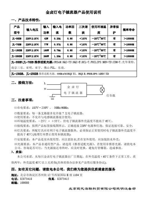
一、产品技术特性:
二、接线方法:
三、注意事项:
⑴市电要求:185V ~ 250V ,50Hz/60Hz;
⑵数量要求:每一条支路最多允许接7支电子镇流器;
⑶使用要求:不允许与电感镇流器混合使用;
⑷环境温度要求:-25℃~ +55℃,但电子镇流器外壳温度不能高于65℃;
⑸接线要求:按照产品标签接线图所示,正确连接220V电源和灯泡;保证连接可靠、安全;
⑹灯具要求:所配灯具应有利于电子镇流器散热,必须保证正常使用时电子镇流器外壳温度不
能高于65℃(地埋灯内禁止使用本镇流器);
⑺安装要求:本产品是室内使用型,应注意防水;若在室外使用,应加装防水外壳;
⑻光源要求:本产品非通用型产品,请选用《推荐适配光源》,若使用非推荐光源,请致电本
公司,咨询是否可行;当光源接近寿终时,应及时更换,避免灯管爆裂,造成事故。
3、质保:
本公司承诺,从每只金卤灯电子镇流器出厂日期起,在外壳温度﹤65℃条件下正常工作,质保两年;外壳温度65℃以上无质保(具体质保办法参见产品售后服务协议)。
四、如有其它问题,请致电本公司,我们将为您提供优质满意的服务
地址:北京市海淀区苏州街12号西屋国际E座1104室
电话:82873418 传真:82873415
邮编:100080
北京现代海联科贸有限公司照明设备部。
镇流器说明书
高压钠灯智能调光型电子镇流器安装使用说明书 大明(FITBRIGHT )公司HPS 系列高压钠灯智能调光型电子镇流器,具有高功率因数,低谐波,恒功率输出,提高光效,性能稳定,以及具有防潮、异常状态保护功能等特点。
广泛应用于城市道路、施工现场、桥梁、铁路、隧道、商场、工厂、宾馆、机场码头、泛光照明等。
一、产品性能特点1、绿色照明,高效照明;2、低谐波(<8%),高功率因数(>0.99);3、输出端短路、断路保护功能;4、恒功率输出,相匹配的光源无频闪;5、智能调光电子镇流器会自动完成过程控制。
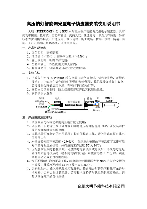
二、安装方法1、“输入”连接220V/50Hz 输入电源(棕色接火线,蓝色接零线,黄绿色接地),“输出”蓝色线接灯管脚外壁金属圈,棕色线接灯管脚中心点,若接反将会降低启动电压,有可能不能启动灯管。
2、安装固定镇流器时,防止端盖变形以降低其抗潮湿性能。
3、安装接线示意图:三、产品使用注意事项 1、镇流器应与标称功率的高压钠灯配套使用;2、镇流器工作时输出端(到灯端)瞬时电压有可能达到3kV ,在安装维护及更换灯泡时请切断电源;3、本镇流器可在指定的电压范围内长时间稳定工作,请勿尝试在超出此电压范围工作;4、本镇流器使用环境温度﹣25~55℃,在超出此范围的环境温度下工作可能对产品寿命造成损害,外壳最高工作温度TC 为80℃;5、因配套高压钠灯特性所致,点燃的灯泡在关闭或熄灭后,必须等灯泡足够冷却才能再次点亮,视不同功率的灯泡,可能需等待1~2分钟,镇流器将自动完成此过程的控制;6、为了不影响灯泡的正常工作,输出端应使用耐压大于600V 且符合安规的电源线,且长度不超过18米(线电容≤2nF );7、为避免触电,输入端地线应可靠接地。
输出端去灯管的两根线不允许与地短路,否则会损坏镇流器。
若需技术支持请与就近的供应商联系,请勿试图拆开产品自行维修。
合肥大明节能科技有限公司 白/棕黑/蓝n。
Tridonic Tridonic数字调光电子镇流器ECO系列产品说明书
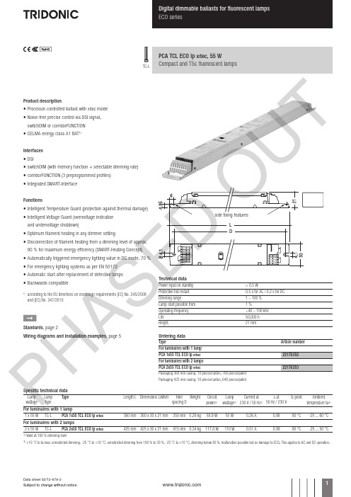
Product description• Processor-controlled ballast with y inside• Noise-free precise control via DSI signal, switchDIM or corridorFUNCTION • CELMA energy class A1 BAT 1)Interfaces • DSI• switchDIM (with memory function + selectable dimming rate)• corridorFUNCTION (3 preprogrammed profiles)• Integrated SMART-Interface Functions• Intelligent Temperature Guard (protection against thermal damage)• Intelligent Voltage Guard (overvoltage indication and undervoltage shutdown)• Optimum filament heating in any dimmer setting• Disconnection of filament heating from a dimming level of approx. 90 % for maximum energy efficiency (SMART-Heating Concept)• Automatically triggered emergency lighting value in DC mode, 70 %• For emergency lighting systems as per EN 50172• Automatic start after replacement of defective lamps• Backwards compatible1)according to the EU directives on ecodesign requirements (EC) No. 245/2009 and (EC) No. 347/2010ÈStandards , page 2Wiring diagrams and installation examples , page 5PCA TCL ECO lp Y , 55 WCompact and T5c fluorescent lampsTC-LTechnical dataPower input on standby < 0.5 WProtective hot restart 0.5 s for AC / 0.2 s for DC Dimming range 1 – 100 %Lamp start possible from 1 %Operating frequency ~40 – 100 kHz Life 50,000 hHeight21 mmOrdering dataTypeArticle number Packaging 425 mm casing: 10 pieces/carton, 640 pieces/palletSpecific technical dataLamp wattageLamp type TypeLength L Dimensions LxWxHHole spacing D Weight Circuit power 1Lamp wattage 1Current at 230 V / 50 Hz 1λ at50 Hz / 230 V tc pointAmbienttemperature ta 2For luminaires with 1 lamp1 x 55 W TC-L PCA 1x55 TCL ECO lp Y 360 mm 360 x 30 x 21 mm 350 mm 0.26 kg 58.9 W 55 W0.26 A0.9880 °C-25 ... 60 °CFor luminaires with 2 lamps2 x 55 WTC-LPCA 2x55 TCL ECO lp Y425 mm 425 x 30 x 21 mm415 mm 0.34 kg117.8 W110 W0.51 A0.9980 °C-25 ... 50 °C1Valid at 100 % dimming level2+10 °C to ta max: unrestricted dimming. -25 °C to +10 °C: unrestricted dimming from 100 % to 30 %. -25 °C to +10 °C, dimming below 30 %: malfunction possible but no damage to ECG. This applies to AC and DC operation.P HA SE U TStandards EN 55015EN 55022EN 60929EN 61000-3-2EN 61347-2-3EN 61547Suitable for emergency installations according to EN 50172Lamp starting characteristics Warm startStarting time 0.5 s with AC Starting time 0.2 s with DC Start at any dimming levelAC operation Mains voltage220–240 V 50/60 Hz198–264 V 50/60 Hz including safety tolerance (±10 %)202–254 V 50/60 Hz including performance tolerance (+6 % / -8 %)DC operation 220–240 V 0 Hz198–280 V 0 Hz certain lamp start 176–280 V 0 Hz operating rangeUse in emergency lighting installations according to EN 50172 or for emergency luminaires according to EN 61347-2-3 appendix J.Light output level in DC operation Default value is 70 %Emergency unitsThe “PCA TCL ECO lp x ” ballasts are compatible with all emergency units from Tridonic. See the table in the data sheet. Also all “5-pole” emergency units can be used. When used with other emergency units tests are necessary.Temperature rangeUnlimited dimming range from 10 °C to ta max. -25 °C to +10 °C: dimming operation from 100 % to 30 %. If dimm level goes below 30 % malfunction possible, but no electronic ballast damage. This applies to AC and DC operation.Mains currents in DC operation (at 70 % light output)TypeWattageMains current at U n = 220 V DCMains current at U n = 240 V DCPCA 1x55 TCL ECO lp X 1x55 W 0.21 A 0.19 A PCA 2x55 TCL ECO lp X2x55 W0.42 A0.38 AHarmonic distortion in the mains supply (at 230 V / 50 Hz)TypeWattage THD357911PCA 1x55 TCL ECO lp X 1x55 W 7.1 5.7 1.0 1.3 1.4 1.2PCA 2x55 TCL ECO lp X 2x55 W4.12.10.60.91.00.8Ballast lumen factor AC operation (AC-BLF) EN 60929 8.1TypeWattageAC-BLF atU = 230 V ACPCA 1x55 TCL ECO lp X 1x55 W 0.98PCA 2x55 TCL ECO lp X 2x55 W0.99The ballast lumen factor for AC operation (AC-BLF) does not alter from U n = 198 V AC to U n = 254 V AC .The ballast lumen factor for DC operation (DC-BLF) on the basis of an automatic power reduction of the ballasts (default value is 70 %) will be smaller than AC. It does not alter in the DC operating range (198–280 V DC ).P HA SE D OU T7550250100908070605040302010digital dimming value relative lighting level in %10090807060504030201001009080706050403020151054321Energy saving PCA TCL ECO lpmains power in %dimming level in %Dimming characteristics as seen by the human eyeDimming characteristics PCA TCL ECO lp1)SMART-LS II lp: article number 86458258DSI PCA TCL ECO lp Xswitch DIM PCA TCL ECO lpXDimmingDimming curve is adapted to the eye sensitiveness.Dimming range 1 % to 100 %Digital control with DSI signal: 8 bit Manchester Code Speed 1 % to 100 % in 1.4 sControl input (D1, D2)Digital DSI signal, push-to-make switch (switchDIM) or a motion detector (corridorFUNCTION) can be wired on the same terminals (D1 and D2).Digital signal DSIThe control input is non-polar and protected against accidental connection with a mains voltage up to264 V. The control signal is not SELV. Control cable has to be installed in accordance to the requirements of low voltage installations.Different functions depending on each module.SMART interfaceAn additional interface for the direct connection of the SMART-LS II lp 1) light sensor or corridorFUNCTION Plugs.Application and functionallity see corridorFUNCTION user manual.SMART-LS II lp 1) light sensor operating mode:The sensor registers actual ambient light and main-tains the individually defined lux level.After every mains reset the SMART interface auto-matically checks for an installed sensor. With the sensor installed the PCA TCL ECO lp x automati-cally runs in the constant lux level mode.ON/OFF switch via mains, switchDIM or DSI signal.DSI signal = 0 switches off,DSI signal ≥ 1 switches on.With switchDIM signals it is possible to change the controlled light level temporarily.Temporarily means that after a switching cycle OFF/ON command the ballast will start at the preset value determined by the SMART-LS II lp. The installa-tion of the two wire bus is according to the appropriate low voltage regulations.switchDIMIntegrated switchDIM function allows a direct connection of a push to make switch for dimming and switching.Brief push (< 0.6 s) switches ballast ON and OFF. The ballasts switch-ON at light level set at switch-OFF.When the push to make switch is held, PCA ballasts are dimmed. After repush the PCA is dimmed in the opposite direction.The switchDIM fade time is set to 3 s from min. to max. in the factory settings. With a 20 s push to the push to make switch this fade time can be changed to 6 s. In this instance the switchDIM application will be synchronized to 50 % light level after 10 s and after 20 s the light level rises to 100 % with the new fade time.At every synchronizsation (10 s keystroke) the device will reset to 3 s (factory setting)In installations with PCAs with different dimming levels or opposite dimming directions (e.g. after a system extension), all PCAs can be synchronized to 50 % dimming level by a 10 s push.Use of push to make switch with indicator lamp is not permitted.Deactivation: If the corridorFUNCTION is wrongly activated in a switchDIM system (for example a switch is used instead of pushbutton), there is the option of installing a pushbutton and deactivating the corridorFUNCTION mode by five short pushes of the button within three seconds.switchDIM and corridorFUNCTION are very simple tools for controlling ballasts with conventional momentary-action switches or motion sensors.To ensure correct operation a sinusoidal mains voltage with a frequency of 50 Hz or 60 Hz is required at the control input.Special attention must be paid to achieving clear zero crossings.Serious mains faults may impair the operation of switchDIM and corridorFUNCTION.Backwards compatibilityWith a simple key combination a PCA TCL ECO lp x can be reset as a normal PCA ECO from the previous generation. Synchronisation simply has to take place three times within one minute (3 x 10 s). To activate the “x ” settings again, synchronisation has to take place four times within one minute.Dimmable ballasts from Tridonic have to be earthed.Loading of automatic circuit breakersAutomatic circuit breaker type C10C13C16C20B10B13B16B20Installation Ø1.5 mm 21.5 mm 21.5 mm 22.5 mm 21.5 mm 21.5 mm 21.5 mm 22.5 mm 2PCA 1x55 TCL ECO lp X 2234485211172426PCA 2x55 TCL ECO lp X12162226681113Continuous operation: to calculate the protective saftey switch see main current, page 1P HA SE D OWiring adviceThe lead length is dependent on the capacitance of the cable.With standard solid wire 0.5/0.75 mm² the capacitance of the lead is 30–80 pF/m. This value is influenced by the way the wiring is made. Lamp connection should be made with symmetrical wiring.Hot leads (9, 10, 15, 16) and cold leads (11, 12, 13, 14) should be separated as much as possible.When using two or more dimmable ballasts in one luminaire with separate dimming controls, the lamp leads must be kept separate.Dimmable ballasts from Tridonic have to be earthed.Installation instructionsWiring type and cross sectionThe wiring can be solid cable with a cross section of 0.5 to 0.75 mm² for push terminal and 0.5 mm² for IDC terminal. For the push-wire connection you have to strip the insulation (8–9 mm).Loosen wire through twisting and pullingwire preparation:Intelligent Temperature GuardThe intelligent temperature guard protects the PCA TCL ECO lp x from thermal overheating by reducing the output power or switching off in case of operation above the thermal limits of the luminaire or ballast. Depending on the luminaire design, the ITG operates at about 5 to 10 °C above Tc temperature.Intelligent Voltage GuardIntelligent Voltage Guard is the name of the new elec-tronic monitor from Tridonic. This innov ative feature of the PCA family of control gear fromTridonic immediately shows if the mains voltage rises above certain thresholds. Measures can then be taken quickly to prevent damage to the control gear.• If the mains voltage rises above approx. 305 V (voltage depends on the ballast type), the lamp starts flashing on and off.• This signal “demands” disconnection of the power supply to the lighting system.corridorFUNCTIONActivation: To activate the corridorFUNCTION a voltage of 230 V simply has to be applied for five minutes at D1, D2. The unit will then switch automatically to the corridorFUNCTION.Deactivation: If the corridorFUNCTION is wrongly activated in a switchDIM system (for example a switch is used instead of pushbutton), there is the option of installing a pushbutton and deactivating the corridorFUNCTION mode by five short pushes of the button within three seconds.The corridorFUNCTION V2 offers the added benefit of a second and third preprogrammed profile, which can be activated by the corridorFUNCTION plugs.Application and functionallity of profiles see user manual.Operating voltageTypeWattage U out PCA 1x55 TCL ECO lp X 1x55 W 250 V PCA 2x55 TCL ECO lp X2x55 W350 VBallastTerminalMaximum capacitance allowed TypeColdHot Cold Hot PCA 1xx TCL ECO lp X11, 129, 10200 pF 100 pF PCA 2xx TCL ECO lp X11, 12, 13, 149, 10, 15, 16200 pF100 pFP HA SE D OU TRFI• Connection to the lamps of the hot leads must be kept as short as possible• Mains leads should be kept apart from lamp leads (ideally 5–10 cm distance)• Do not run mains leads adjacent to the electronic ballast • Twist the lamp leads• Keep the distance of lamp leads from the metal work as large as possible• Mains wiring to be twisted when through wiring • Keep the mains leads inside the luminaire as short as possibleGeneral adviseElectronic ballasts are virtually noise free.Magnetic fields generated during the ignition cycle can cause some background noise but only for a few milliseconds.For further technical information please visit PCA TCL ECO lp X 1x36–58 WPCA TCL ECO lp X 2x36–58 WDimmable ballasts from Tridonic have to be earthed.* * * leads 9, 10: keep wires short, max. 1.0 mleads 11, 12: max. 2.0 m; ballast must be earthed * * digital signal (DSI) or switchDIM* ** leads 9, 10, 15, 16: keep wires short, max. 1.0 mleads 11, 12, 13, 14: max. 2.0 m; ballast must be earthed* * digital signal (DSI) or switchDIMOperation on DC voltageOur ballasts are construed to operate DC voltage and pulsed DC voltage.To operate ballasts with pulsed DC voltage the polarity is absolute mandatory.Isolation and electric strength testing of luminairesElectronic devices can be damaged by high voltage. This has to be considered during the routine testing of the luminaires in production.According to IEC 60598-1 Annex Q (informative only!) or ENEC 303-Annex A, each luminaire should be sub-mitted to an isolation test with 500 V DC for 1 second. This test voltage should be connected between the interconnected phase and neutral terminals and the earth terminal.The isolation resistance must be at least 2 MΩ.As an alternative, IEC 60598-1 Annex Q describes a test of the electrical strength with 1500 V AC (or 1.414 x 1500 V DC ). To avoid damage to the electronic devices this test must not be conducted.P HA SU。
ZXD1500_30A开关整流器用户手册

通俗易懂
详细说明
内容结构
内容详细
您对本资料的 改进建议
内容深度 表达简洁 增加图形
增加实例
增加 FAQ 其他
您对中兴通讯 用户资料的 其他建议
前言
手册说明
ZXD1500 30A 高频开关整流器是中兴通讯股份有限公司自主开发的通信电源用 的开关整流器之一。它采用了国际上先进的整流器软开关技术,可广泛用于各种 交换设备、微波通信、移动基站以及光纤传输等通信设备中。
本手册介绍 ZXD1500 整流器的功能特点、性能参数、工作原理、外形结构、安装 调试、使用操作、日常维护和运输存储。
声明:由于产品和技术的不断更新、完善,本资料中的内容可能与实际产品不完 全相符,敬请谅解。如需查询产品的更新情况,请联系当地办事处。
目录
第 1 章 概述................................................................................................................................................1-1 1.1 简介 .................................................................................................................................................1-1 1.2 主要特点 .........................................................................................................................................1-1 1.3 性能指标 .........................................................................................................................................1-2 1.3.1 输入特性 ...............................................................................................................................1-2 1.3.2 输出特性 ...............................................................................................................................1-2 1.3.3 执行标准 ...............................................................................................................................1-3 1.4 内部保护功能 .................................................................................................................................1-3 1.4.1 交流输入欠压保护 ...............................................................................................................1-3 1.4.2 交流输入过压保护 ...............................................................................................................1-3 1.4.3 输出过压保护 .......................................................................................................................1-3 1.4.4 输出限流保护 .......................................................................................................................1-3 1.4.5 过热保护 ...............................................................................................................................1-3 1.4.6 三遥接口功能 .......................................................................................................................1-3 1.4.7 外形尺寸及重量 ...................................................................................................................1-4 1.4.8 工作环境 ...............................................................................................................................1-4 1.5 工作原理 .........................................................................................................................................1-4