SICK_PLS配置指导书
SICK HIPERFACE DSL服务器技术介绍说明书

H I P E R F A C E D S L ® | S I C K8021413/2017-05-31Subject to change without notice2Overhead_left CHARACTER FORMAT_OVERHEAD_GREYExpanded product diversity with HIPERFACE DSL ®By opening the interface, SICK is anticipating customer require-ments for a wider range of motor feedback systems with HIPER-FACE DSL ®. For drive manufacturers, this results in access to an expanded range of products in rotary and linear environments as well as various performance ranges of motor feedback systems.The security of an open, established interfaceCountless manufacturers of motors and drives worldwide have already implemented HIPERFACE DSL ® – proof of the high level of confidence in this innovative interface. Deciding on HIPERFACE DSL ® reduces implementation effort for motion control custom -ers to only one interface. At the same time, the customer has freedom in the choice of motor feedback systems. HIPERFACE DSL ® therefore offers long-term investment security.Customized connection to Industry 4.0By opening HIPERFACE DSL ®, SICK is supporting open system architectures which are the foundation for Industry 4.0, and is creating the prerequisites for smart drive technology. HIPERFACE DSL ® makes it possible to slim down the system, increase inte-gration density of data and functions and continuously monitor conditions.YOUR GATEWAY TO THE FUTUREAs an open interface, HIPERFACE DSL ® combines all the advantages of a digital real-time interface – established One Cable Technology and an enormous increase in efficiency - and is therefore a foundation for Industry 4.0.H I P E R F A C E D S L®|S I C K 8021413/2017-05-31Subject to change without notice 3YOUR DIGITAL GATEWAY TO THE FUTURE HIPERFACE DSL®Saves space when installing motorsThe reduced number of required con-nections makes a more compact motor design possible. In the future, a smaller servo drive will also be possible in many applications.Reducing the drag chainOnly one cable between the inverter and motor cuts the drag chain in half and enables rapid cabling and fewer sources of error.Efficient installationThe reduced number of components simplifies installation and saves time and personnel costs for commissioning and maintenance.Certified safetyHIPERFACE DSL® is characterized by increased resistance to interference and has safety technology certification for ap-plications up to safety integrity level SIL3 (IEC 61508) and performance level e (EN ISO 13849-1). HIPERFACE DSL® can therefore be easily integrated into safety applications.Condition monitoring Continuous condition monitoring for the servo drive enables remote control of temperature, speed, LED current, supply voltage and rotation speed - throughout the entire service life. This increases machine availability and supports time management of the machine. Sustainable mechanicalengineeringHIPERFACE DSL® allow for compact control cabinets, fewer cables, lower weight and reduced material and energy consump-tion whilst achieving the same high level of performance. The One Cable Technology therefore makes an important contributionto sustainability in machine engineering. AN OVERVIEW OF HIPERFACE DSL®MANY YEARS OF INTERFACE EXPERTISEWith the development of the SSI, HIPERFACE ® and HIPERFACE DSL ® interfaces, SICK has managed to set industry standards for over three decades. Long-standing partnerships in the area of motor feedback systems, paired with the strong innovation ability of SICK, have contributed to fulfilling customer requirements with customized solutions and anticipation of technological trends.SSI interfaceIn 1985, SICK developed the synchronous-serial SSI interface together with the former Max Stegmann GmbH (now a part of SICK). The patented open interface between absolute encoders and controls quickly became the established solution in industry. The SSI interface for the first time allowed fast data transmission of, for example, 24 bits through only 4 wires instead of through 24 wires, as was the case previously. This results in a dramatic decrease in costs by reducing the need for copper wires as well as increased flexibility and bending strength of the cable.HIPERFACE ® interfaceIn 1996, SICK launched the HIPERFACE ® interface, creating another market standard. This hybrid interface between motor feedback system and drive enables trans-mission of analog and digital signals. The HIPERFACE ® interface reduces the previous three data cables for position, speed and commutation to one single cable. Furthermore, HIPERFACE ® for the first time enabled the direct connection of all signals to the drive.8021413/2017-05-31 • D M _C D G M C /G D • S u b j e c t t o c h a n g e w i t h o u t n o t i c eHIPERFACE DSL ® YOUR DIGITAL GATEWAY TO THE FUTURESICK AG | Waldkirch | Germany | You can find more information at: /hiperfacedsl。
SICK_CDS配置指导书

BMW Brilliance Automotive SICK_CDS Manual Body Shop 2008-4-16 Zhang Mingli Page 1SICK配置指导书SICK_CDSSICK_CDS ManualShenyang 2008-4-16Sheer Driving PleasureBMW Brilliance Automotive SICK_CDS Manual Body Shop 2008-4-16 Zhang Mingli Page 2前言 本文档针对SICK公司的CDS系列产品,详细阐述了CDS的操作和配置。
本文档可作为更改安全扫描区域、更改SICK组态信息、新扫描器的初次使用、 故障诊断等的操作指导。
本文档未能说明之处,请参看SICK公司的CDS操作指导书。
SICK_CDS ManualShenyang 2008-4-16Sheer Driving Pleasure1BMW Brilliance Automotive SICK_CDS Manual Body Shop 2008-4-16 Zhang Mingli Page 3一、连接笔记本和SICK_CDS1.1.1 连接好笔记本和SICK_CDS。
连接电缆是专用的数据线。
SICK_CDS ManualShenyang 2008-4-16Sheer Driving PleasureBMW Brilliance Automotive SICK_CDS Manual Body Shop 2008-4-16 Zhang Mingli Page 4二、更改已有SICK的安全扫描区本章介绍更改已有SICK安全扫描区的方法。
SICK_CDS ManualShenyang 2008-4-16Sheer Driving Pleasure2BMW Brilliance Automotive SICK_CDS Manual Body Shop 2008-4-16 Zhang Mingli Page 5二、更改已有SICK的安全扫描区2.1.1 打开相应SICK_CDS的管理程序。
SICK条码扫描器使用

说明 可代表准备就绪、读取成功、 读不到、条码个数大于/小于 设定值、匹配、不匹配、参 考值与限制值的比较等条码 器状态信息,由下拉菜单选 择决定。
有关、小声、大声三种
ୋ 13 䔍 38 䔍
广州市施克传感器有限公司
(5)Match Code Parameters 匹配条码参数:
会出现绿色 “Connected” 若出现红色 “ No Connection”即表示连接失败.
ୋ 5 䔍 38 䔍
7. 若连接失败,可选择握手图框,自动测试通信协定
广州市施克传感器有限公司
8. 若还不能连接,请检查通信电缆是否连接正确,例如: Com Port 是否正确? RS232 中,针角是否按如下连接? RxD → TxD , TxD → RxD GND → GND .
ୋ 10 䔍 38 䔍
广州市施克传感器有限公司
(3)Reading Trigger Parameters 阅读触发信号源参数:
英文 Sensor Input (Active High) Sensor Input (Active Low)
Serial Interface Free Running with Timeout OPC-Trigger Reflector Polling Continuous Read
广州市施克传感器有限公司
CLV 条码阅读器 使用指南
ୋ 1 䔍 38 䔍
广州市施克传感器有限公司
目
录
1. 条码阅读器的安装步骤----------------------------- (1) 2. 条码阅读器扫描频率设定方法----------------------- (4) 3. CVL Setup 软件使用说明--------------------------- (5) 4. 附录 1:CLV44X 动态聚焦功能使用方法--------------- (23) 5. 附录 2:SICK CAN-SCANNER-NETWORK 介绍------------- (29)
SICK中国公司IDM1xx_2xx配对设置及Profinet通讯手册说明书

IDM1xx_2xx配对设置及Profinet通讯手册类型:调试指导版本:V1.0 日期:2017-5-26目录1.手持读码器类型 (3)2.硬件连接 (3)3.手持枪的供电及状态说明 (4)3.1.手持枪供电 (4)3.2.手持枪指示灯状态及含义 (4)4.手持枪设置连接模式 (6)4.1.无线蓝牙手持枪支持的PICO、PAIR模式 (6)4.2.PAIR模式 (6)4.3.DPM功能激活 (7)5.手持抢参数设置 (7)6.CDF600-2200设置 (9)6.1.硬件设置 (9)6.2.软件设置 (10)7.PLC通讯设置 (10)7.1.下载GSDML文件 (10)7.2.添加GSD文件 (12)7.3.设备组态并设置CDF600-220x (13)7.4.通讯字符握手说明 (14)7.5.通讯字符握手设置 (15)1. 手持读码器类型本操作手册针对以下产品中除IDM142 WIFI、IDM162 WIFI型外其他所有接口为RS232型手持式条码阅读器。
2. 硬件连接我公司Profinet网关有两种型号,本文中以常用型号CDF600-2200为例,设备连接方式如下图所示:3. 手持枪的供电及状态说明3.1. 手持枪供电3.2. 手持枪指示灯状态及含义4. 手持枪设置连接模式4.1. 无线蓝牙手持枪支持的PAIR 、PICO模式PAIR模式表示手持枪主体和底座为一对一连接,为最通用模式;PICO模式为手持枪主体和底座为一对多连接。
一个蓝牙底座最多支持7个手持枪主体。
4.2. PAIR模式4.3. DPM功能激活(可选)5. 手持抢参数设置按照以下表格从上往下扫描:顺序内容条形码1 恢复出厂默认设置2 设置为RS232通讯模式3 进入设置模式设置波特率为96004设置STX/ETX为前后缀56 设置数据位格式为:n,8,1.7 删除CR结束符8 结束设置如果有条件,建议先把手持枪底座与电脑通过RS232进行通讯连接,打开串口监控工具,查看数据格式是否已经设置成功。
SICK 西克 条码阅读器调试手册-CLV6系列

OFF ON
输出信号为+24V,
最大电流100mA
13 16
14
GND Result1 T+
S3
ON
CDB420-001
OFF
CDB420-001接线端子
15 24 25 26 17 27 28
29
R+ T- R- GND SGND SGND Sensor1 +24V
蜂鸣器及报警灯 继电器
R+ T+ R- T- GND RS422-RS232转换器
3、单台条码阅读器参数设置及调试
广州市施克传感器有限公司
1、SICK 扫描器的调试和参数设置一般通过扫描器的 Terminal 端口进行。也就 是通过接线盒 CDB420 中的 AUX Interfac(e 9 针插头)将扫描器与计算机相连接。 连接电缆的选用 2-3 交叉串口通信电缆,电缆的连线如下图所示,
Multiread:重复次数,默认为 3,1-99 可选。速度越快,设定重复次 数越少。
Free:指条码的长度是随意的,只要是这类条码都识别。 Fixed:指条码的长度是固定的,跟此长度不同的不识别。
第 17 页 共 36 页
广州市施克传感器有限公司
在 Serial 下: (一般要修改,根据实际需要选择)
在 Output Control 下:(一般要修改,根据实际需要选择)
第 14 页 共 36 页
英文 End of Trigger As soon as possible
End of Label New Label
Single
Multiple
Good Read Condition Match1 Condition TeachIn1 Condition TeachIn2
SICK3000设置手册
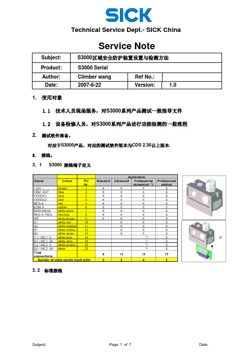
Service NoteSubject: S3000区域安全防护装置设置与检测方法Product: S3000 SerialAuthor: Climber wang Ref No.:Date: 2007-6-22 Version: 1.01. 使用对象1.1 技术人员现场服务,对S3000系列产品测试一般指导文件1.2 设备检修人员,对S3000系列产品进行功能检测的一般流程2. 测试软件准备。
对应于S3000产品,对应的测试软件版本为CDS 2.36以上版本.3. 接线。
3.1 S3000 接线端子定义3. 2 标准接线4. 参数设置一般步骤及需保存文件。
4.1 打开设置软件,测试软件版本为CDS2.36及以上.User category: Authorized Client Password :SICKSAFE4.2 配置参数,设置扫描仪的各项功能.4.3 设置保护区域的大小,包括保护区域和警告区域.4.4 参数以及区域设置完成后,下载S3000 System->Configuration Draft->Transmit4.5 在出现故障时,需要下载并保存的文件.4.5.1 记录Sensor Head Error history4.5.2 I/o module error history 4.5.3 记录当前参数设置在对S3000进行检测后,故障历史记录需与现场服务报告一起保存。
************************************************** - 在服务现场,未经培训的人员不允许打开前镜。
End - ***************************************************。
SICK SLS Visualization Software 快速入门指南说明书
Safety Laser Scanner Visualization SoftwareFor microScan3 and outdoorScan3Quickstart GuideQuickstart GuideInhalt1. Display scanner data in 7 steps (3)Step 1 – Connect Scanner (3)Step 1.1 – Power Supply (3)Step 1.2 – Ethernet Cable (3)Step 2 – Set up Ethernet Connection (4)Step 2.1 – Read out IP address using Safety Designer (4)Step 2.2 – Read out IP address on display of safety laser scanner (4)Step 3 – Download Software (4)Step 4 – Preparing SLS Visualization Software (5)Step 4.1 –Edit “executable” file to correct IP address (5)Step 4.2 – Replace IP address (5)Step 4.3 – Save file (6)Step 5 – Preparing the computer for the network connection. (7)Step 6 – Open the SLS Visualization Software (9)Step 7 – SLS Visualization Software is displayed (9)2. Using the SLS Visualization Software on WinCC – Overview (10)WinCC Professional (TIA Portal) (10)WinCC Advanced (TIA Portal) (11)Quickstart Guide – Safety Laser Scanner Visualization Software This document describes the steps to run the SLS Visualization Software for microScan3 and outdoorScan3.Pre-requisites:Windows PC (Win XP and up).o Note 1: The SLS Visualization Software does not run on Windows CE.W indows CE has reached End of Life Support in 2018; therefore SICK cannotprovide the SLS Visualization Software for Windows CE.o Note 2: Many SIEMENS HMI's using TIA Portal are based on Windows / WinCC → therefore many SIEMENS HMI's are supported.Supported devicesAll microScan3 devices - except all microScan3 Core I/O versionsOnly outdoorScan3 Pro EtherNet IP1. Display scanner data in 7 stepsStep 1 – Connect ScannerFirst, connect the safety laser scanner to the HMI or computer on which the SLS Visualization Software is used.Step 1.1 – Power SupplyConnect scanner to power supply with 24V. Find appropriate cables on .As an example, the following cable can be used for power connection for microScan3 ProPROFINET:Step 1.2 – Ethernet CableConnect safety laser scanner to HMI or computer using an Ethernet cable. Find appropriate cables on . As an example following cable can be used for microScan3 Pro PROFINET :Step 2 – Set up Ethernet ConnectionThe next step is to set up the Ethernet Connection. In order to do this the IP address of the safety laser scanner needs to be known. There are two simple ways to read it out.Step 2.1 – Read out IP address using Safety DesignerOpen Safety Designer, connect to device (e.g. by using USB cable) and see address on pageaddressing.Step 2.2 – Read out IP address on display of safety laser scannerUse the Buttons on the Safety Laser Scanner. (Device Info Network IP address)Step 3 – Download SoftwareClick link to download the SLS Visualization Software:- SICK Internal: Download here:https:///pages/viewpageattachments.action?pageId=393349683&preview=/393349683/393349693/microScan3-VISU-Diagnostics_V1-0.rar- SICK External: receive Secureshare Link by your SICK Contact.When the download is finished open the ZIP file as follows:Unpack ZIP file to afolder of choiceStep 4 – Preparing SLS Visualization SoftwareWhen the file is unzipped, following files should be included:Step 4.1 –Edit “executable” file to correct IP addressThe IP address that is programmed must be edited before starting the THE SLS VISUALIZATION SOFTWARE.Step 4.2 – Replace IP addressA window will open in which the specified IP address must be exchanged by the address of the safety laserscanner. If you do not have this IP address then go back to “Step 2”.Right click on the file "Execute_192_168_1_5.bat " allows editing of the file.Replace the pre-programmed IP address with the actual IP address of the scanner.Step 4.3 – Save fileOnce the IP address is set correctly safe the executable with its new name. The name should include the actual IP addressStep 5 – Preparing the computer for the network connection.Using Windows computers the connection may have to set in the Control panel. See steps below.Open Network andSharing Center.Go to …Ethernet“Go to “Properties”Go to …Internetprotocol, Version 4 (TCP/IPv4)“Enter the IP address andsubnet mask. Subnet mask is the same asthe scanner.Note that this is the IP address ofthe HMI VISU, not of thescanner. Thus: Same subnet, nutdifferent IP address, however insame range. Confirm …OK“.Step 6 – Open the SLS Visualization SoftwareOpen the bat file.Step 7 – SLS Visualization Software is displayedOpen the bat file that was created previously with the actual IP address in itThe VISU tool will open and should automatically connect to the safety laser scanner.2. Using the SLS Visualization Software on WinCC – OverviewWinCC (TIA Portal) is available in different variants WinCC Basic, WinCC Comfort, WinCC Advanced and WinCC Professional. In addition, there are the two runtime systems WinCC Runtime Advanced and WinCC Runtime Professional. The difference between the variants lies primarily in the configurable devices.WinCC Professional (TIA Portal)With WinCC Professional the THE SOFTWARE DIAG tool can be opened with an exe file via a c script. To do this the following code must be written into the script.WinCC Advanced (TIA Portal)To start the HMI VISU DIAG tool the following software is needed on WinCC Advanced: The tool can then be implemented into the WinCC advanced software.The tool can now be displayed via WinCC Advanced.The …diag2“-Button, will start the defined eventHere you can choose at which event an actionshould be executed. Under …Program name“ youhave to link the tool you want to open.。
SICK条码阅读器

广州市施克传感器有限公司
完成接线后需要将网络中的第一个接线盒和最后一个 接线盒的 S2(CAN-Term)开关置于 ON 的位置,也就是打开 CAN 网络的终端电阻。扫描器之间的 CAN 总线的网络连线需 要采用屏蔽双绞线。
扫描器 CAN 网络电气连接图
ୋ 7 䔍 38 䔍
条码质量设置(Codelabel Quality): 一般设为 Standard,如条码黑白对比度太 小,选用 Low contract;若有斑点,选用 Speckled。
ୋ 10 䔍 38 䔍
广州市施克传感器有限公司
在 Reading Conf.-Distance Con 下: (一般要修改,根据实际安装距离)
采用带有屏蔽的通信电缆。
ୋ 5 䔍 38 䔍
广州市施克传感器有限公司
注: CDB 接线盒到 PC 的 RS232 电缆需要采用带有屏蔽的通信 电缆,电缆长度建议不要超过 10m。
2.2 多台扫描器通过 CAN 总线方式连接 如果需要使用多台扫描器组成 CAN 总线网络的时候,则需要按照以下方式进
ୋ 15 䔍 38 䔍
广州市施克传感器有限公司
在 Code Confi.下:(一般要修改,根据实际需要选择)
英文 Symbologies Decoder
中文 条码类型 解码方式
Number of Codes Code position
条码数量 条码位置
Min. distance between Labels Symbology Parameters
条码之间最小距离
对已选条码类型的 参数做具体设置
说明 在相应码型前打钩,可多选 可选标准型或智能型(SMART, 可提高对损坏、倾斜或有污点 条码的阅读率,但反应较慢) 设定一次读取的条码数量 若选择比较,满足最小距离条 件的位置不同的条码将作为 新条码读入
- 1、下载文档前请自行甄别文档内容的完整性,平台不提供额外的编辑、内容补充、找答案等附加服务。
- 2、"仅部分预览"的文档,不可在线预览部分如存在完整性等问题,可反馈申请退款(可完整预览的文档不适用该条件!)。
- 3、如文档侵犯您的权益,请联系客服反馈,我们会尽快为您处理(人工客服工作时间:9:00-18:30)。
BMW Brilliance Automotive SICK_PLS Manual Body Shop 2008-4-1 Zhang Mingli Page 1SICK配置指导书SICK_PLSSICK_PLS ManualShenyang 2008-4-1Sheer Driving PleasureBMW Brilliance Automotive SICK_PLS Manual Body Shop 2008-4-1 Zhang Mingli Page 2前言 本文档针对SICK公司的PLS系列产品,详细阐述了PLS的操作和配置。
本文档可作为更改安全扫描区域、更改SICK组态信息、新扫描器的初次使用、故障 诊断等的操作指导。
本文档未能说明之处,请参看SICK公司的PLS操作指导书。
SICK_PLS ManualShenyang 2008-4-1Sheer Driving Pleasure1BMW Brilliance Automotive SICK_PLS Manual Body Shop 2008-4-1 Zhang Mingli Page 3一、连接笔记本和SICK_PLS1.1.1 连接好笔记本和SICK_PLS。
连接电缆是标准RS232数据线。
(连接方式如下图)DB9公头(针侧,接SICK) DB9母头(孔侧,接笔记本)2 3 52 3 5SICK_PLS ManualShenyang 2008-4-1Sheer Driving PleasureBMW Brilliance Automotive SICK_PLS Manual Body Shop 2008-4-1 Zhang Mingli Page 4二、更改已有SICK的安全扫描区本章介绍更改已有SICK安全扫描区的方法。
SICK_PLS ManualShenyang 2008-4-1Sheer Driving Pleasure2BMW Brilliance Automotive SICK_PLS Manual Body Shop 2008-4-1 Zhang Mingli Page 5二、更改已有SICK的安全扫描区2.1.1 打开相应SICK_PLS的管理程序。
(PLS-LSI-Benutzersoftware 03.61)SICK_PLS ManualShenyang 2008-4-1Sheer Driving PleasureBMW Brilliance Automotive SICK_PLS Manual Body Shop 2008-4-1 Zhang Mingli Page 6二、更改已有SICK的安全扫描区2.2.1 如果接线连接正常,会出现如下界面,询问是否接收当前SICK的配置信息。
点击“是(Yes)”按钮。
SICK_PLS ManualShenyang 2008-4-1Sheer Driving Pleasure3BMW Brilliance Automotive SICK_PLS Manual Body Shop 2008-4-1 Zhang Mingli Page 7二、更改已有SICK的安全扫描区2.2.2 如果出现如下界面,表明接线连接不正常。
应连续点击“否(No)”或“取消 (cancel)”。
重新连接。
SICK_PLS ManualShenyang 2008-4-1Sheer Driving PleasureBMW Brilliance Automotive SICK_PLS Manual Body Shop 2008-4-1 Zhang Mingli Page 8二、更改已有SICK的安全扫描区2.3.1 接收信息完成后,会出现用户登陆的对话框,选择“Authorized client”,密码 是“SICK_PLS(注意大写)”。
点击“登录(log on)”按钮。
SICK_PLS ManualShenyang 2008-4-1Sheer Driving Pleasure4BMW Brilliance Automotive SICK_PLS Manual Body Shop 2008-4-1 Zhang Mingli Page 9二、更改已有SICK的安全扫描区2.3.2 如果密码遗忘,可以点击“帮助(Help)”按钮,在帮助文档中可以找到SICK的默 认密码(SICK_PLS)。
SICK_PLS ManualShenyang 2008-4-1Sheer Driving PleasureBMW Brilliance Automotive SICK_PLS Manual Body Shop 2008-4-1 Zhang Mingli Page 10二、更改已有SICK的安全扫描区将扫描区域写入SICKTransfer monitoring area2.4.1 登陆后,管理软件的界面及操作按钮的说明如下。
编辑扫描区域Edit monitoring area编辑组态信息Edit Configuration将扫描区域读取到笔记本 将组态读取到笔记本Receive Configuration Receive monitoring area将组态写入SICKTransfer Configuration扫描区域学习Teach-in monitoring area监视扫描区域Monitor monitoring areaSICK_PLS ManualShenyang 2008-4-1Sheer Driving Pleasure5BMW Brilliance Automotive SICK_PLS Manual Body Shop 2008-4-1 Zhang Mingli Page 11二、更改已有SICK的安全扫描区2.4.2 扫描区域选择。
图中蓝色区域为安全扫描区,紫色区域为报警扫描区。
安全保护区No.1 –Field/Protective field报警保护区No.1 –Field/Warning fieldSICK_PLS ManualShenyang 2008-4-1Sheer Driving PleasureBMW Brilliance Automotive SICK_PLS Manual Body Shop 2008-4-1 Zhang Mingli Page 12二、更改已有SICK的安全扫描区2.5.1 选择蓝色的安全扫描区,点击“编辑安全区域(Edit monitoring area)”按钮。
图 中蓝色区域为安全区,由若干个关键点勾画而成,绿色线条为实际的物体感应线。
编辑扫描区域Edit monitoring areaSICK_PLS ManualShenyang 2008-4-1Sheer Driving Pleasure6BMW Brilliance Automotive SICK_PLS Manual Body Shop 2008-4-1 Zhang Mingli Page 13二、更改已有SICK的安全扫描区2.5.2 将鼠标移动到需要调整的关键点位置,待其变成小手图标后,移动该点进行编 辑。
若要新加点,用鼠标在预期位置双击鼠标即可加入关键点。
SICK_PLS ManualShenyang 2008-4-1Sheer Driving PleasureBMW Brilliance Automotive SICK_PLS Manual Body Shop 2008-4-1 Zhang Mingli Page 14二、更改已有SICK的安全扫描区2.6.1 选择紫色的警告扫描区,点击“编辑安全区域(Edit monitoring area)”按钮。
一 般我们不设置警告区可以删除。
右键 选择全部关键点 删除 。
编辑扫描区域Edit monitoring areaSICK_PLS ManualShenyang 2008-4-1Sheer Driving Pleasure7BMW Brilliance Automotive SICK_PLS Manual Body Shop 2008-4-1 Zhang Mingli Page 15二、更改已有SICK的安全扫描区2.6.2 选择全部关键点后 删除 ,点击“是(yes)”按钮。
删除所有关键点。
SICK_PLS ManualShenyang 2008-4-1Sheer Driving PleasureBMW Brilliance Automotive SICK_PLS Manual Body Shop 2008-4-1 Zhang Mingli Page 16二、更改已有SICK的安全扫描区2.7.1 点击“将扫描区域写入SICK(Transfer monitoring area)”按钮,在出现的保存界 面中保存文件。
将扫描区域写入SICKTransfer monitoring areaSICK_PLS ManualShenyang 2008-4-1Sheer Driving Pleasure8BMW Brilliance Automotive SICK_PLS Manual Body Shop 2008-4-1 Zhang Mingli Page 17二、更改已有SICK的安全扫描区2.7.2 然后出现选择写入区域界面,选择相应的被修改的扫描区或“全选(add all)”。
再点击“传输(transfer)”按钮,进行写入。
SICK_PLS ManualShenyang 2008-4-1Sheer Driving PleasureBMW Brilliance Automotive SICK_PLS Manual Body Shop 2008-4-1 Zhang Mingli Page 18二、更改已有SICK的安全扫描区2.7.3 系统会报告报警扫描区写入完成,点击“是(yes)”。
SICK_PLS ManualShenyang 2008-4-1Sheer Driving Pleasure9BMW Brilliance Automotive SICK_PLS Manual Body Shop 2008-4-1 Zhang Mingli Page 19二、更改已有SICK的安全扫描区2.7.4 询问是否写入安全扫描区,点击“是(yes)”。
SICK_PLS ManualShenyang 2008-4-1Sheer Driving PleasureBMW Brilliance Automotive SICK_PLS Manual Body Shop 2008-4-1 Zhang Mingli Page 20二、更改已有SICK的安全扫描区2.7.5 安全扫描区写入完成,点击“是(yes)”。