2.4 GHz天线的选择和选择标准
国家无委对2.4G频段的规定
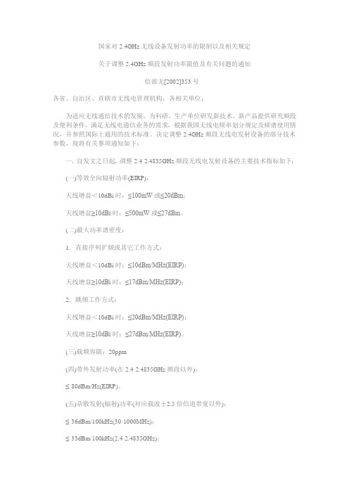
国家对2.4GHz无线设备发射功率的限制以及相关规定关于调整2.4GHz频段发射功率限值及有关问题的通知信部无[2002]353号各省、自治区、直辖市无线电管理机构,各相关单位:为适应无线通信技术的发展,为科研、生产单位研发新技术、新产品提供研究频段及便利条件,满足无线电通信业务的需求,根据我国无线电频率划分规定及频谱使用情况,并参照国际上通用的技术标准。
决定调整2.4GHz频段无线电发射设备的部分技术参数,现将有关事项通知如下:一、自发文之日起,调整2.4-2.4835GHz频段无线电发射设备的主要技术指标如下:(一)等效全向辐射功率(EIRP):天线增益<10dBi时:≤100mW或≤20dBm;天线增益≥10dBi时:≤500mW或≤27dBm。
(二)最大功率谱密度:1.直接序列扩频或其它工作方式:天线增益<10dBi时:≤10dBm/MHz(EIRP);天线增益≥10dBi时:≤17dBm/MHz(EIRP);2.跳频工作方式:天线增益<10dBi时:≤20dBm/MHz(EIRP);天线增益≥10dBi时:≤27dBm/MHz(EIRP)。
(三)载频容限:20ppm(四)带外发射功率(在2.4-2.4835GHz频段以外):≤-80dBm/Hz(EIRP)。
(五)杂散发射(辐射)功率(对应载波±2.5倍信道带宽以外):≤-36dBm/100kHz(30-1000MHz);≤-33dBm/100kHz(2.4-2.4835GHz);≤-40dBm/1MHz(3.4-3.53GHz);≤-40dBm/1MHz(5.725-5.85GHz);≤-30dBm/1MHz(其它1-12.75GHz)。
二、2.4GHz频段作为无线局域网、无线接入系统、蓝牙技术设备、点对点或点对多点扩频通信系统等各类无线电台站的共用频段。
符合技术要求的各类无线电通信设备在2.4-2.4835GHz频段内与无线电定位业务及工业、科学和医疗等非无线通信设备共用频率,均为主要业务。
2.4G天线设计完整指南设计(原理、设计、布局、性能、调试)
本文章使用简单的术语介绍了天线的设计情况,并推荐了两款经过测试的低成本PCB天线。
这些PCB天线能够与PRoC?和PSoC?系列中的低功耗蓝牙(BLE)解决方案配合使用。
为了使性能最佳,PRoC BLE和PSoC4 BLE2.4GHz射频必须与其天线正确匹配。
本应用笔记中最后部分介绍了如何在最终产品中调试天线。
1、简介天线是无线系统中的关键组件,它负责发送和接收来自空中的电磁辐射。
为低成本、消费广的应用设计天线,并将其集成到手提产品中是大多数原装设备制造商(OEM)正在面对的挑战。
终端客户从某个RF产品(如电量有限的硬币型电池)获得的无线射程主要取决于天线的设计、塑料外壳以及良好的PCB布局。
对于芯片和电源相同但布局和天线设计实践不同的系统,它们的RF(射频)范围变化超过50%也是正常的。
本应用笔记介绍了最佳实践、布局指南以及天线调试程序,并给出了使用给定电量所获取的最宽波段。
图1.典型的近距离无线系统设计优良的天线可以扩大无线产品的工作范围。
从无线模块发送的能量越大,在已给的数据包错误率(PER)以及接收器灵敏度固定的条件下,传输的距离也越大。
另外,天线还有其他不太明显的优点,例如:在某个给定的范围内,设计优良的天线能够发射更多的能量,从而可以提高错误容限化(由干扰或噪声引起的)。
同样,接收端良好的调试天线和Balun(平衡器)可以在极小的辐射条件下工作。
最佳天线可以降低PER,并提高通信质量。
PER越低,发生重新传输的次数也越少,从而可以节省电池电量。
2、天线原理天线一般指的是裸露在空间内的导体。
该导体的长度与信号波长成特定比例或整数倍时,它可作为天线使用。
因为提供给天线的电能被发射到空间内,所以该条件被称为“谐振”。
图2. 偶极天线基础如图2所示,导体的波长为λ/2,其中λ为电信号的波长。
信号发生器通过一根传输线(也称为天线馈电)在天线的中心点为其供电。
按照这个长度,将在整个导线上形成电压和电流驻波,如图2所示。
2.4g天线效率范围

2.4g天线效率范围
2.4GHz 天线的效率通常取决于多个因素,包括天线设计、制造质量、安装环境等。
一般来说,2.4GHz是用于Wi-Fi、蓝牙等通信标准的频段,而天线的效率对通信性能至关重要。
以下是一些关于2.4GHz 天线效率的一般性信息:
1.内置设备天线:一些设备(如无线路由器、蓝牙设备)内置了
小型PCB(Printed Circuit Board)天线。
这类天线的效率通常
在50%到70%之间,但具体取决于设计和制造质量。
2.外置天线:外置天线的效率可以更高,通常在70%到90%之间。
这种类型的天线常用于无线路由器、Wi-Fi适配器、蓝牙设备等。
3.定向天线:一些特定应用需要定向天线,例如用于点对点通信
的定向天线或用于无线网络的方向性天线。
这些天线的效率可
以更高,达到90%以上。
4.安装环境:天线效率还受到安装环境的影响。
例如,天线在受
阻碍或有多径效应的环境中可能表现不佳,导致效率下降。
5.设计技术:使用不同的天线设计技术(例如贴片天线、螺旋天
线、定向天线等)也会影响天线的效率。
要准确评估特定天线的效率,通常需要进行天线测试或查阅制造商提供的技术规格。
在实际应用中,保持天线的正确安装和定期检查可以确保天线效率的最佳性能。
无线路由器天线的选择原理
无线路由器天线的选择原理
无线路由器天线的选择原理如下:
1. 频段匹配:选择与无线设备频段相匹配的天线,例如
2.4GHz频段的设备需选择2.4GHz的天线。
2. 增益匹配:根据无线设备的需求,选择相应增益的天线,增益越高,传输距离越远。
3. 方向性匹配:根据无线设备的使用环境,选择定向或全向天线。
4. 线损匹配:考虑无线信号在传输过程中的线损,选择较低的线损天线。
5. 天气条件:根据使用环境的天气条件,选择耐腐蚀、耐高温等天气条件较好的天线。
6. 品牌选择:选择信誉度较高、质量有保障的品牌天线。
综上所述,选择适合的无线路由器天线需要综合考虑多种因素,确保其能够达到最优的传输效果。
ANTCOR 蚂蚁系列网络产品 2.4GHz超级无线终端机 说明书
目录ANTCOR蚂蚁系列网络产品 (1)2.4GHz 超级无线终端机车 (1)一、产品概述 (3)二、液晶配置 (5)2.1欢迎界面 (5)2.2屏幕菜单 (5)2.2.1设备信息 (5)2.2.2无线信息 (6)2.2.3无线扫描 (6)2.2.4学习过程 (7)2.2.5恢复出厂设置 (7)三、WEB页面配置 (8)3.1本地设置 (8)3.2登录设备 (8)3.3无线模式介绍 (9)3.3.1站点模式设置 (10)3.3.2中继模式设置 (12)3.3.3 3G无线路由器模式设置 (13)3.3.4无线路由器PPPoE设置 (14)3.3.5无线路由器设置 (15)3.4如何设置学习过的信息 (17)3.5高级设置 (19)3.6系统服务 (19)3.7系统设置 (19)3.8论坛 (22)附录A:无线安全设置说明 (22)附录B:无线工具使用说明 (23)7.1校正天线 (24)7.2 Ping (24)7.3跟踪路由 (24)7.4站点侦测 (25)附录C:FAQ(蚂蚁战车无线问答) (25)声明未经过本公司明确书面许可,任何单位或者个人不得擅自仿制、复制、眷抄或译本部分或者全部内容。
不得以任何形式或方法进行商品传播或用于任何商业、赢利目的。
本手册所提到的产品规格和资讯仅供参考,如内容有更新,恕不另行通知。
除非有特殊约定,本手册仅做为使用指导,本手册中的所有陈述,信息等均不构成任何形式的担保。
一、产品概述感谢您使用本公司ANTCOR蚂蚁系列网络产品2.4GHz 超级无线终端机(蚂蚁战车)。
这份手册将会帮助您完成所有的安装使用。
本包装内应该包含下列对象:2.4GHz 超级无线终端机(蚂蚁战车)5dBi天线5V、2A电源交叉网线保修卡注意:如有缺少请与经销商联系。
ANTCOR蚂蚁系列网络产品室内型超级无线终端机(蚂蚁战车),工作在2.4GHz频段,符合IEEE802.11b/g标准,采用OFDM(正交频分复用)技术,实际数据速率高达20Mbps 以上,具有速率高、传输距离远等特点,是小区无线覆盖/农村无线覆盖/校园无线覆盖/无线城市覆盖应用的最佳选择。
【选择攻略】2.4GHz 频段天线选择

2.4GHz 频段天线选择天线(antenna)是一种能量变换器,它把传输线上传播的导行波,变换成在无界媒介中传播的电磁波,或者进行相反的变换。
对于设计一个应用于射频系统中的小功率、短距离的2.4GHz无线收发设备,天线的设计和选择是其中的重要部分,良好的天线系统可以使通信距离达到最佳状态。
2.4GHz天线的种类也很多,不同的应用需要不用的天线。
天线简介图1 天线传输原理为保证天线的传输效率,天线的长度大约是电磁波波长的1/4,所以信号频率越低,波长越长,天线的长度越长;信号频率越高,波长越短,天线的长度越短。
则常用的2.4GHz 频段频率高,波长短,天线的长度短,可用内置天线,也可以用外置天线。
天线做的更短,如1/8波长或1/16波长,也可以使用,只是效率会下降。
某些设备会采用“短天线+LNA”的方式,也能达到长天线的接收效果。
但是短天线要达到长天线的发射效果,就需要提升发射功率了,因此对讲机需要发射信号,都是长的外置天线,而FM收音机只收不发,有内置接收天线。
例如2G(900MHz)、4G(700-2600MHz)、WIFI和蓝牙(2.4GHz)、GPS(1.5GHz),这些常用的物联网通信方式,可以做内置天线。
对于手持机、穿戴设计、智能家居等小尺寸产品,很少使用外置天线,普遍采用内置天线。
集成度高,产品外观更美观,性能比外置天线略弱一点。
物联网、智能硬件产品,要联网传输数据,都需要有天线。
空间越小、频段越多,天线设计越复杂。
外置天线一般都是标准品,买频段合适的,无需调试,即插即用。
例如快递柜、售货机这些,普遍使用磁吸的外置天线,吸在铁皮外壳上即可。
这些天线不能放在铁皮柜里面,金属会屏蔽天线信号,所以只能放在外面。
优点是使用方便、价格便宜,缺点是不能用在小尺寸产品上。
天线类别那如何从众多的2.4GHz天线中选择出适合自己无线收发设备的2.4GHz天线,接下来就通过对2.4GHz天线的分类和分类对比来介绍如何选择2.4GHz天线。
2.4 GHz天线和滤波器的器件选择与设计因素考虑
2.4 GHz天线和滤波器的器件选择与设计因素考虑2.4 GHz是现代RF设计的最佳选择,可以通过提及一些知名品牌来证明:蓝牙,ZigBee,Wi-Fi和WLAN。
人们还可以将细胞应用投入混合物中。
显然,这种未经许可的频段允许各种手持式,移动式和固定式基站设计,这些设计可以点对点通信,也可以通过蜂窝或网状网络进行路由。
但是,人气带来了技术问题。
即使使用通道分段,一个标准的信号也可以踩到另一个标准信号并阻塞吞吐量。
幸运的是,频率分配,算法,时间切片和后退定时器等技术有助于让每个人分享乐队并一起玩得很好。
即便如此,实现最佳性能和满足可靠性目标需要卓越的天线设计,并密切关注相关组件,以保持一切谐振。
更重要的是,无论是平衡还是单端,发射增益和接收灵敏度取决于天线的物理特性及其辐射方向图。
本文将介绍2.4 GHz天线以及使其工作的耦合网络。
它研究了可在2.4 GHz ISM频段工作的商用单芯片天线。
它讨论了与使用单芯片天线相关的天线类型,RF分布模式以及范围和设计问题,而不是连接器安装的外部天线或PCB天线。
信号路径使天线按需运行的关键是天线的信号路径。
虽然大多数RF芯片具有良好的输出级,但仍可能需要匹配,滤波和分离,特别是如果单个天线用于多个通信标准。
因此,典型的RF 输出级仍然必须连接到单端,平衡或双工匹配网络(图1)。
图1 :虽然RF芯片具有很多功能,但与天线的匹配仍然是工程师的责任,并且根据所使用的天线类型以及它是否是共享RF级而不同。
例如,使用蓝牙的应用程序。
您可以使用带通或低通滤波器组合的单端输出级将IC驱动器级布线和匹配到天线(图2A)。
更好的方法是通过平衡- 不平衡转换器和带通滤波器使用平衡差分驱动器级(图2B)。
图2A:单个- 结束连接可以利用较低成本的过滤器和匹配元素。
2.4Gwifi的频道信道20M40M的概念,区别
2.4Gwifi的频道信道20M40M的概念,区别单天线 : 20MHz max 65Mbps, 40MHz max 150Mbps双天线 : 20MHz max 130Mbps, 40MHz max 300Mbps40MHZ 实际上是⽤了两个频道, 20MHZ 实际上是⽤了1个频道。
20MHz对应的是65M带宽穿透性好传输距离远(100⽶左右)40MHz对应的是150M带宽穿透性差传输距离近(50⽶左右)可能某channel下20MHz, 就会⽤2.42-2.44GHz40MHz, 就会⽤2.41-2.45GHz2.4G频率因为⼲扰不能上40MHZ的话,需要改⼀下设置,在⾼级设置⾥⾯把20/40MHZ共存选项取消,就可以了。
20MHz和40MHz并存,如果是⼀般家⾥⽤的话就别开了,时常会有很多设备接⼊的话就开着,就是接⼊设备数量不稳定可以打开这⾥“带宽”指的是⽆线⽹卡连接⽆线路由器时的信道带宽,⽽不是⽆线⽹卡的传输速率,也不是 ISP 运营商提供的带宽。
信道带宽,是指限定了允许通过该信道的信号下限频率和上限频率,也就是限定了⼀个频率通带。
802.11n ⽀持 20MHz 和 20MHZ/40MHz 通道;以前的标准中(11a、11b 和 11g)使⽤的是 20MHZ 的带宽。
802.11n 标准⽀持 20MHz 和 40MHz 信道,其中 40MHz 信道将是最宽的信道,由两个邻近、遗留的 20MHz 频谱信道组成; 当然也可以只⽤ 20MHz 信道,这个是由具体的情况(⽆线⽹络标准)决定的。
当⽹络模式为 11b、 11g 和 11b/g 混合⽹络模式时,它只能使⽤ 20MHz 的信道带宽,当⽹络模式设置为 11b/g 混合模式时,信道带宽是不可以选择的,它只能使⽤ 20MHz 的信道带宽,当⽹络模式更改为 11b/g/n 混合⽹络模式时,它就可以同时使⽤ 20MHz 和 40MHz 信道带宽,。
- 1、下载文档前请自行甄别文档内容的完整性,平台不提供额外的编辑、内容补充、找答案等附加服务。
- 2、"仅部分预览"的文档,不可在线预览部分如存在完整性等问题,可反馈申请退款(可完整预览的文档不适用该条件!)。
- 3、如文档侵犯您的权益,请联系客服反馈,我们会尽快为您处理(人工客服工作时间:9:00-18:30)。
Options and Selection Criteria for 2.4 GHz Antennas2.4 GHz is a sweet spot for modern-day RF design can be demonstrated by mentioning a few well-known names: Bluetooth, ZigBee, Wi-Fi and WLAN. One can also toss cellular applications into the mix. Clearly, this unlicensed band allows a variety of handheld, mobile, and fixed base station designs that communicate either point-to-point, or are routed through a cellular or mesh network.Popularity, however, brings technical issues. Even with channel s egmentation, one standard’s signal can step on another and clog up throughput. Fortunately, frequency allocations, algorithms, time-slicing, and back-off timers, among other techniques, help let everyone share the band and play nicely together.Even so, achieving optimum performance and meeting reliability goals calls for superior antenna design and close attention to the associated components that keep everything resonant. What is more, whether balanced or single ended, the transmit gain and receive sensitivity depend on the physical nature of the antenna and its radiation pattern.This article takes a look at 2.4 GHz antennas and the coupling networks that make them work. It examines commercially available single-chip antennas that are designed to work in the 2.4 GHz ISM band. It discusses antenna types, RF distribution patterns, and range and design issues associated with using a single-chip antenna, as opposed to a connector- mounted external antenna or PCB antenna. All parts, datasheets, development kits and training modules referenced here are available on Digi-Key’s website.The signal pathKey in making your antenna perform as desired is the signal path to the antenna. While most RF chips have good output stages, matching, filtering, and splitting still may be needed, especially if a single antenna is used for more than one communications standard. As such, the typical RF output stages must still connect to either a single ended, balanced, or diplexed matching network (Figure 1).Figure 1: While RF chips house a lot of functionality, matching to the antenna is still the engineer’s responsibility and will be different depending on the type of antenna used and if it is a shared RF stage.Take, for example, an application that uses Bluetooth. You may have a single-ended output stage using a bandpass or lowpass filter combination to route and match the IC driver stage to the antenna (Figure 2A). A better approach is to use a balanced differential driver stage through a balun and band-pass filter (Figure 2B).Figure 2A: A single-ended connection can take advantage of lower cost filter and matching elements.Figure 2B: Balanced output stages used precisely matched impedance stages specific to a chip manufacturer’s part.Fortunately, several hundred RF-Specific low-pass, band-pass, and high-pass filters as well asRF-Specific baluns and matching arrays are readily available from over half a dozen manufacturers. These can effectively block and attenuate the frequencies from cellular bands and wireless systems and pass impedance-matching, clean signals to the RF stages of the specific chip you are using.For dense designs, a part to know about is the multi-layer Taiyo Yuden FI212C245072-T and similar parts in the series. Taiyo Yuden has found a way of updating its core technology using a multi-layer inductor to develop a 1.25 x 2 mm, combination-balanced bandpass filter and balun in a single package. Impedance values from 50 to 100 Ohms are typical, but you should note that the parts to use can be specific to a specific RF chip manufacturer.This last item is important, as IC manufacturers will go to great lengths to characterize their RF stage and these characteristics can vary from manufacturer to manufacturer. Further, keep in mind that it is important to review the transfer characteristics of any balun and filter, especially when combined. With the Taiyo Yuden parts, frequency plots are a good way to start (Figure 3), but you will want to make your own characteristic response graphs if you deviate from the man ufacturer’s suggested layout and handling.Figure 3: Attenuation and pass-band characteristics of a combined filter and baluns can give good performance with reduced PCB footprint. In this case, a 2.4 to 2.5 GHz pass-band is created.Both chipmakers and antenna, filter, and coupling device manufacturers are good design resources. Often, app notes and reference designs will specify the exact part number to use. To help, Taiyo Yuden offers two EMC simulators: One for waveform ¹ and one for T/Pi filters.²The antennaSo now you have matched your RF IC stage to the antenna with good filters and baluns (if used). Now it is time to focus attention on the antenna.For higher cost and maximum transmit power and receive sensitivity, external antenna jacks and units should be used. For high volume and cost-sensitive designs, this is typically not the way to go, especially if you can use PCB or single-chip monolithic antennas.A PCB antenna can provide good transmit gain and receive sensitivity. Simple dipoles are easy to design and layout as a fractional or integer distance corresponding to wavelengths. As long as tight controls on the PCB manufacturing process do not let the stack up impedances vary, a reliable and repeatable design can take advantage of the PCB antenna approach.Still, the antenna will need to be isolated from other circuitry. This takes up a good amount of space on the board where an RF ground plane and unpopulated areas are precisely located and coordinated with the mechanical enclosures and materials used in the enclosures.While not achieving the same performance levels as some PCB antennas, the single-chip solution allows much smaller footprints with uniform and consistent performance. Take, for example,the Johanson2450AT18B100E passive, 50 Ohm ceramic surface-mount chip antennas. These parts use a low temperature, co-fired ceramic technology (LTCC) keeping them small for pick-and- place machines while providing near omni-directional radiation and linear polarization.The up to 3W parts target Bluetooth, Wireless LAN, ZigBee, and WiMax applications. Specified at less than 2 for a standing wave ratio, the parts are well-centered around the 2.4 to 2.5 GHz bands (Figure 4).Figure 4: The Johanson single-chip surface mount antennas are specified to maintain a standing wave ratio of less than two, resulting in a cleaner signal with less spurious and wasted power.A similar single-chip antenna is the TDK ANT040015CCS2442MA1 with its center frequency of 2.442 GHz. While the max VSWR is higher than the Johanson part – at 3.5 max. TDK provides a PCB reference design with a shielded feed point that can be located remotely from the digital logic. This can help provide good range compared to when the antenna is right next to the digital logic (Figure 5).Figure 5: Following manufacturer’s guidelines and suggested PC board layouts can help quickly determine performance baselines. Iterative design techniques can then be used to tweak the design to optimum performance.Keep in mind that it is important to search for specifics. The TDK ANT series ranges from 2.0 x 1.25 x 0.5 mm all the way up to 9.8 x 3 x 4 mm in size. Each has its own characteristics and radiation patterns. Similarly, the Taiyo Yuden AF and AH Series contain specific part numbers on datasheets and reference materials for RF standards of interest including Bluetooth, WiMax, GPS, ZigBee, and WLAN, to name a few.An interesting technology to be aware of is the Taiyo Yuden RadiEdge configuration where the radiation pattern is designed to emanate from the edge of a PC board. A part such as the AH316M245001-T is designated for 2.4 GHz designs and uses a 3.2 x 1.6 x .5 mm footprint with a 5 mm x 6 mm keep-out area. It may be helpful to note that the radiation pattern is also somewhat directional with around a 73 percent efficiency rating. Also, if the keep-out areas are done correctly, the RadiEdge layout can be in the middle of the printed circuit board using a two-way symmetrical pattern. This can be useful when the periphery of a PC board is tightly space constrained and may have several connectors.Training from Taiyo Yuden and Johanson Technology is available on the Digi-Key website, and provides a good introduction to the capabilities and limitations of these types of single-chip antennas and matching components.In summary, this article has discussed design considerations and part selection criteria associated with 2.4 GHz antennas and filters. It has demonstrated how device manufacturers have stepped up to the plate to provide compact, well-designed antenna and antenna-matching solutions. Following the manufacturers’ guidelines and suggested layouts will, in the least, get your designs off to a good start.。