23_FB-900 Spark Rod Adjustment Spec(C)(1st)
美国火花科技产品说明书

WARNINGRISK OF IMPROPER FLAME DETECTION•Install only in areas in accordance with the environmental and hazardous area ratings.•Carefully review mounting area and position in accordance with the Performance Appendix and the User Manual to ensure optimal flame detection regarding the angle of device and unobstructed view.•Avoid potential sources of direct or indirect radiation in the flame detector field of view.•Do not touch the sensors on the front of the electronics module.•Avoid direct sunlight into the flame detector window –use provided sunshade,aim flame detectors down at 40degrees or more when possible,and use multiple detectors to cover hazardous areas from different directions.•Avoid close proximity to rapid modulation/chopping of sunlight (creating moving dark shadows)as optical sensor performance can be reduced,e.g.close trees in the wind,rotating blades.•Use shielded cable for all wirings and ground the shield at one end as detailed in the Wiring section.•Keep all devices and wire runs away from mercury vapor lights,variable speed drives,radio repeaters and other sources of electromagnetic interference.•Follow local cabling and glanding rules.•Seal all unused conduit entries and install proper drains/traps by local codes.•Do not try to service parts inside the electronics module,there are no field serviceable parts,just modulereplacement.CAUTIONRISK OF PRODUCT DAMAGE•Do not install in an area where there are incidents of high mechanical damage.•Protect controllers and monitors from physical damage (forklifts,etc.).•Failure to follow all warnings cautions,and instructions may void the warranty.•To maintain IPX6integrity,seal conduit entries with thread sealantsuch as Loctite 565or approvedequivalent.WARNINGRISK OF EXPLOSION•Ensure power is off and no hazardous gases nor dusts are present before installing or opening the device.•Use only hazardous location approved plugs plugs M25or ¾’’NPT as marked on product.SPECIFIC CONDITIONS OFUSE:WARNINGELECTROSTATIC HAZARD,DO NOT RUB WITH DRY CLOTH•Contact the manufacturer for dimensional information on the flameproof joint specifications if repair is required.QUICKREFERENCE GUIDEfor Hazardous Location InstallationSeries Flame Detectors and associated Test LampsThe Honeywell®Analytics Flame Detectors and Test Lamps are hazardous area products.They are factory calibrated,and the robust sealed design with no moving parts allows for mounting in any orientation even in harsh environments.These products are available in either a 316Stainless Steel or Low Copper Aluminum.Nameplate TagRepresentative Markings are displayed in the figure below.Additional regional marks(such as South Korea and Russia)and installation specific marks(such as ABS)may also be present.See individual nameplates for specific approvals applicable to each product. Note:Some products require18in.of conduit.(See individual nameplate for specifics). Electrical Ratings•Test Lamps(battery powered):12VDC,600mA•FS10:12VDC;60mA•FS10-R-A:Max29VDC,120mA;Relay24VDC,1A•FS20X and FS24X Series:Max32VDC,150mA;Relay24VDC,1A •FS20XP and FS24XP:Consumption18-32VDC,500mA max;Relay 24VDC/AC,2A maximumInstalling the Flame DetectorAll products are provided with a flameproof and explosion-proof enclosure and have been approved for use in Class1and Zone1 environments as specified on the individual product nameplate tag. Note:NFPA72and other local codes have specific requirements for flame detectors installations and must be consulted as necessary.Must only be installed by appropriately trained and accredited personnel.1.Securely mount the detector using minimum1/4-20or M6sized fasteners.Note:We recommend angling all detectors down at least40degrees fromhorizontal.2.Loosen,but do not remove the set screw on the coverassembly.3.Loosen the3Philips screws and remove the electro-opticalDetector Module and place face up in a safe location.Note:Do not drop the Detector Module and do not touch the sensor array.4.Connect the cable gland or conduit to the detector enclosurevia the¾’’NPT or M25openings,as per national electricalcodes for the install location.Connect the appropriate wiresrated for minimum85ºC to the field connectors provided asper the wiring diagram on the cover of the electro-opticalDetector Module.Ensure the enclosure is properly grounded in accordance withall local codes.Use shielded cable for all communications connections andground one end of the shield following the product manual. 5.Configure following the product's User Manual andPerformance Appendix to this guide.Note:Refer to the fuel and sensitivity settings table to determine the correctconfiguration.6.Connect the field connectors back onto the electro-opticalDetector Module and secure the module into the enclosurewith the Philips screws.7.Install the cover and ensure the O-ring is compressed.Tighten the cap screw on the cover assembly.Make a roughField of View(FoV)adjustment by aiming the detector at thearea you want to cover.8.Tighten all bolts when product has been fully configured andtested accordance with the product manual.Note:Detector functionality and communication should be tested to confirmcorrect FoV and configuration in the final system.Generic NameplateViewWARNINGRISK OF EXPLOSIONDo not connect test lamps to external power sources.Test lamps are battery operated only.Do not open when explosive gases are present. Charging permitted in safe environment only.Contact UsAmericas SwitzerlandHoneywell Analytics Main Phone:+41216953000405Barclay Boulevard***************************** Lincolnshire,Illinois60069Tel:+18479558200Asia PacificToll free:+18005380363Honeywell Industrial Safety***********************434,Worldcup Buk-ro,Mapo-gu Europe,Middle East,and Africa Seoul03922Honeywell International Sarl South Korea Piece16Tel:+82(0)2690903001180Rolle**************************Manuals,software,and other information about thisproduct are available atCopyright©2022,1701M5000HL Rev E October11,2022。
Hobart HP Series Proofer Replacement Parts Catalog

CAT ALOG OF REPLACEMENT PARTSA p r o d u c t o f H OB A R T 701 S. R I D G E A V E N U E T R O Y , O H I O 45374-0001HP SERIES PROOFERMODEL HP1MODEL HP2ML-132394ML-132291ML-132395ML-132292ML-132396ML-132293ML-132397ML-132294ML-132398ML-132295ML-132399ML-132296ML-132400ML-132303ML-132401ML-132304ML-132402ML-132305ML-132403ML-132306ML-132404ML-132307ML-132405ML-132308MODEL HP3ML-132367PRIOR MLS COVERED IN THIS CATALOG MODEL HP1ML-132285ML-132286ML-132287ML-132288ML-132289ML-132290ML-132298ML-132299ML-132301ML-132302HP SERIES PROOFER REPLACEMENT PARTSML-132289ML-132290ML-132298ML-132299ML-132301ML-132302HP SERIES PROOFER REPLACEMENT PARTSHP SERIES PROOFER REPLACEMENT PARTSHP SERIES PROOFER REPLACEMENT PARTSTable of Contents7CONTROL PANEL (PREV. CONSTRUCTION, MFD PRIOR TO 1/3/05)9CONTROL PANEL (CURRENT CONSTRUCTION, MFD AFTER 1/3/05)11SERVICE ENTRANCE (PREVIOUS CONSTRUCTION)13SERVICE ENTRANCE (CURRENT CONSTRUCTION)15SINGLE WIDE CABINET (PREV. CONSTRUCTION, MFD PRIOR TO 1/3/05) 17SINGLE WIDE CABINET (CURRENT CONSTRUCTION, MFD AFTER1/3/05)19DOUBLE WIDE CABINET (PREV. CONSTRUCTION, MFD PRIOR TO 1/3/05)23DOUBLE WIDE CABINET (CURRENT CONSTRUCTION, MFD AFTER 5/1/05)25TRIPLE WIDE CABINET (ML-132367) (PREV. CONSTRUCTION, MFD PRIOR TO 1/3/05)27TRIPLE WIDE CABINET (ML-132367) (CURRENT CONSTRUCTION, MFD AFTER 1/3/05)29SINGLE DOOR ASSEMBLY (PREV. CONSTRUCTION, MFD PRIOR TO 1/3/05)31SINGLE DOOR ASSEMBLY(CURRENT CONSTRUCTION, MFD AFTER 1/3/05)33DOUBLE DOOR ASSEMBLY35TRIPLE DOOR ASSEMBLY (ML-132367)37TRIM AND INTERIOR BUMPERS (PREVIOUS CONSTRUCTION)39TRIM AND INTERIOR BUMPERS (CURRENT CONSTRUCTION)41STEAM UNIT43DRAIN ASSEMBLY45EXTERIOR WATER SUPPLYCONTROL PANEL(PREV. CONSTRUCTION, MFD PRIOR TO 1/3/05)HP SERIES PROOFER REPLACEMENT PARTSHP SERIES PROOFER REPLACEMENT PARTSCONTROL PANEL(PREV. CONSTRUCTION, MFD PRIOR TO 1/3/05)PART OF PART AMT. ILLUS.PL-57385101-1P2168-00001Plate - Control Panel (1)201-1P2024-00002Plate - Control Panel (Blank) (1)301-100V21-00092Gasket 4 Ft..............................................................................................................................AR 401-1P1854-00001Panel - Control (Incls. Items 1, 3, 5, 6, & 7). (1)501-100V16-0279H Overlay (1)601-1M3001-00003Spacer - PC Board (8)701-1P1255-00005Board - PC Control (1)CONTROL PANEL(CURRENT CONSTRUCTION, MFD AFTER 1/3/05)HP SERIES PROOFER REPLACEMENT PARTSHP SERIES PROOFER REPLACEMENT PARTSCONTROL PANEL(CURRENT CONSTRUCTION, MFD AFTER 1/3/05)PART OF PART AMT. ILLUS.PL-57745101-1P2168-00003Plate - Control Panel (1)201-1P2024-00002Plate - Control Panel (Blank) (1)301-100V21-00092Gasket 4 Ft..............................................................................................................................AR 401-1P1854-00003Panel - Control (Advanced) (Incls. Items 1, 3, 5, 6, & 7) (1)501-100V16-0599H Overlay (1)601-1M3001-00003Spacer - PC Board (8)701-100V16-00624Board - PC Control (1)SERVICE ENTRANCE (PREVIOUS CONSTRUCTION)HP SERIES PROOFER REPLACEMENT PARTSSERVICE ENTRANCE(PREVIOUS CONSTRUCTION)PART OF PART AMT. ILLUS.PL-57396101-1P2030-00101Solenoid Assy. (1- & 2-Duct Unit) (1)201-100V17-00339Elbow 90 Deg. 3/8 NPTM x 3/8 CC (Brass) (1)301-100V11-00102Pipe - Bushed Chase (1/2 NPT) (1)401-1P2025-00001Box - Component (1)501-1P2026-00001Panel - Side, Component Box (2)601-1P1749-00001Beeper Assy (1)701-1000V5-00164Spacer (4)801-1P1384-00003Conduit - Wire Package (1-Wide) (1)901-1P1384-00004Conduit - Wire Package (2-Wide) (1)1001-1P1214-00006Board - Power Supply (1)1101-1000V6-00070Relay - Fan DPDT 1/4Hp., 120 VAC.......................................................................................AR 1201-1000V6-00225Relay - Heater. (1)1301-1000V5-00059Bushing - Snap (1)1401-1000V5-00105Terminal (1 & 2 Duct)..............................................................................................................AR 1501-1000V5-00209Terminal (3 Duct) (1)1601-1000V5-00106End - Section (600 V.) (1)1701-1000V5-00210End - Section Flat Base (1)1801-1000V6-00191Breaker - Circuit (15 A., 120/240 V.) (1)1901-100V11-00139Box - Breaker (1)2001-1P1869-00001Cover Assy. - Component Box (1 Duct Unit, 1 Ph.) (1)2101-1P1869-00002Cover Assy. - Component Box (2 Duct Unit, 1 Ph.) (1)2201-1P1869-00003Cover Assy. - Component Box (3 Duct Unit, 1 Ph.) (1)2301-1P1869-00004Cover Assy. - Component Box (1 Duct Unit, 3 Ph.) (1)2401-1P1869-00005Cover Assy. - Component Box (2 Duct Unit, 3 Ph.) (1)2501-1P1869-00006Cover Assy. - Component Box (3 Duct Unit, 3 Ph.) (1)2601-1P2048-00001Box Assy. - Junction (2)2701-1P2030-00201Conduit - Air Duct (1-, 2-, & 3-Duct Unit) (1)2801-1P2048-00001Box Assy. - Junction (1)2901-1P2030-00203Conduit - Air Duct (3-Duct Unit) (1)3001-1P2030-00202Conduit - Air Duct (2- & 3-Duct Unit) (1)3101-1P2048-00001Box Assy. - Junction (1)01-1P2030-00010Box - Standard Control (1-Duct Unit, 1 & 3 Ph.) (1)01-1P2030-00011Box - Standard Control (2-Duct Unit, 3 Ph.) (1)01-1P2030-00013Box - Standard Control (3-Duct Unit, 3 Ph.) (1)01-1P2030-00015Box - Standard Control (2-Duct Unit, 1 Ph.) (1)01-1P2030-00016Box - Standard Control (3-Duct Unit, 1 Ph.) (1)01-1P2030-00001Box - Standard Control (1-Duct Unit) (1)01-1P2030-00002Box - Standard Control (2-Duct Unit) (1)01-1P2030-00003Box - Standard Control (3-Duct Unit) (1)01-1P2030-00017Box - Advanced Control (1-Duct Unit, 1 & 3 Ph.) (1)01-1P2030-00018Box - Advanced Control (2-Duct Unit, 1 Ph.) (1)01-1P2030-00019Box - Advanced Control (2-Duct Unit, 3 Ph.) (1)01-1P2030-00020Box - Advanced Control (3-Duct Unit, 1 Ph.) (1)01-1P2030-00021Box - Advanced Control (3-Duct Unit, 3 Ph.) (1)01-1000V6-00241(1-Duct Unit) Holder - Fuse (Single) (1)01-1000V6-00242(2-Duct Unit) Holder - Fuse (Double) (1)01-1000V6-00243(3-Duct Unit) Holder - Fuse (Triple) (1)01-1000V6-00244Fuse (20 Amp.)........................................................................................................................AR(CURRENT CONSTRUCTION)SERVICE ENTRANCE(CURRENT CONSTRUCTION)PART OF PART AMT. ILLUS.PL-57646101-1P2030-00101Solenoid Assy. (1- & 2-Duct Unit) (1)201-1P2030-00102Solenoid Assy. (3-Duct Unit) (1)301-100V17-00075Valve - Solenoid (2-Way) (1)401-100V17-00339Elbow 90 Deg. 3/8 NPTM x 3/8 CC (Brass) (1)501-100V11-00102Pipe - Bushed Chase (1/2 NPT) (1)601-1P2025-00003Base - Component (1)701-1P2026-00002Panel - Side (Component Box) (2)801-1P1749-00001Beeper Assy (1)901-1000V5-00164Spacer (4)1001-100V16-00627Board - Power Supply (Advanced) (1)1101-1000V5-00096Block - Distribution (1)1201-1000V5-00037Lug - Terminal (1)1301-100V10-00234Terminal - Section, Flat Mount (600 V.) (1)1401-100V10-00235End - Section, Flat Mount (600 V.) (1)1501-1000V5-00059Bushing - Snap (1)1601-100V10-00245Fuse (25 Amp.) (1 & 3 Ph. & 3 PH.)........................................................................................AR 1701-100V10-00232Fuse Holder.............................................................................................................................AR 1801-1000V6-00191Breaker - Circuit (15 A., 120/240 V.) (1)1901-100V11-00139Box - Breaker (1)2001-1P2196-00001Cover Assy. - Component Box (1-Duct Unit, 1 Ph.) (1)2101-1P2196-00002Cover Assy. - Component Box (2-Duct Unit, 1 Ph.) (1)2201-1P2196-00003Cover Assy. - Component Box (3-Duct Unit, 1 Ph.) (1)2301-1P2196-00004Cover Assy. - Component Box (1-Duct Unit, 3 Ph.) (1)2401-1P2196-00005Cover Assy. - Component Box (2-Duct Unit, 3 Ph.) (1)2501-1P2196-00006Cover Assy. - Component Box (3-Duct Unit, 3 Ph.) (1)2601-100V11-0024C Box Assy. - Junction................................................................................................................AR 2701-1P2030-00201Conduit - First Air Duct (1-, 2-, & 3-Duct Unit). (1)2801-100V11-0024C Box Assy. - Junction (1)2901-1P2030-00202Conduit - Second Air Duct (2- & 3-Duct Unit) (1)3001-1P2030-00203Conduit - Third Air Duct (3-Duct Unit) (1)3101-100V11-0024C Box Assy. - Junction (1)3201-100V11-00102Nipple - Bushed Chased (1)3301-100V17-00075Valve - Solenoid 2-Way (1)3401-1P2030-00103Solenoid Assy. (3-Duct Unit) (1)3501-100V17-00339Elbow 90 Deg. 3/8 NPTM x 3/8 CC (Brass) (1)01-1P1875-00002Sensor Assy. - Humidity W/Filter (1)01-1P2030-00017Box - Advanced Control (1-Duct Unit, 1 & 3 Ph.) (1)01-1P2030-00018Box - Advanced Control (2-Duct Unit, 1 Ph.) (1)01-1P2030-00019Box - Advanced Control (2-Duct Unit, 3 Ph.) (1)01-1P2030-00020Box - Advanced Control (3-Duct Unit, 1 Ph.) (1)01-1P2030-00021Box - Advanced Control (3-Duct Unit, 3 Ph.) (1)(PREV. CONSTRUCTION, MFD PRIOR TO 1/3/05)SINGLE WIDE CABINET(PREV. CONSTRUCTION, MFD PRIOR TO 1/3/05)PART OF PART AMT. ILLUS.PL-57391101-1P1898-00001Duct - Ceiling (1)201-1P1851-00001Panel - Ceiling.........................................................................................................................AR 301-1000V5-00059Bushing - Snap (Plastic)..........................................................................................................AR 401-1000V5-00073Bushing - Snap........................................................................................................................AR *501-100V21-00092Gasket - PVC-Extruded ("B" Shape).......................................................................................AR 601-1P1851-00002Ceiling Assy. - Half Panel.. (1)*701-100V21-00092Gasket - PVC-Extruded ( B Shape) 30 Ft...............................................................................AR 801-1P1839-00001Panel Assy. - Rear (1)901-100V18-00144Latch - Cam Lock (2)1001-100V18-00145Receptacle - Cam Lock (2)*1101-100V21-00092Gasket - PVC-Extruded ("B" Shape).......................................................................................AR 1201-100V18-00144Latch - Cam Lock....................................................................................................................AR 1301-100V18-00145Receptacle - Cam Lock...........................................................................................................AR *1401-100V21-00092Gasket - PVC-Extruded ("B" Shape).......................................................................................AR 1501-1P1841-00002Wall - Half Weldment (2)1601-1P1841-00001Wall Assy. (RH) (1)1701-100V18-00145Receptacle - Cam Lock...........................................................................................................AR *1801-100V21-00092Gasket - PVC-Extruded ("B" Shape).......................................................................................AR 1901-1P1997-00001Channel - Base Side (30 In.) (1)2001-1P1997-00004Channel - Base Side (50 In.) (1)2101-1P1997-00002Channel - Base Side (63 In.) (1)2201-1P1997-00005Channel - Base Side (83 In.) (1)2301-1P1997-00003Channel - Base Side (96 In.) (1)2401-1P1997-00006Channel - Base Side (116 In.) (1)2501-100V21-0005C Caulk - Silicone (Clear) (Tube) (1)2601-1P2038-00001Floor (30 In. STD) (1)2701-1P2038-00002Floor (63 In. STD) (1)2801-1P2038-00005Floor (83 In. STD) (1)2901-1P2038-00003Floor (96 In. STD) (1)3001-1P2038-00006Floor (116 In. STD) (1)3101-1P2038-0001P Floor (30 In. Pass Thru) (1)3201-1P2038-0002P Floor (63 In. Pass Thru) (1)3301-1P2038-0005P Floor (83 In. Pass Thru) (1)3401-1P2038-0003P Floor (96 In. Pass Thru) (1)3501-1P2038-0006P Floor (116 In. Pass Thru) (1)3601-1P1996-00001Channel - Base Rear (1)3701-1000V4-00073Anchor - Drop-In 1/4-20...........................................................................................................AR 3801-1000V4-0073A Tool - Setting (1)3901-1P1843-00002Wall Assy. (LH) (1)4001-100V18-00144Latch - Cam Lock....................................................................................................................AR *4101-100V21-00092Gasket - PVC-Extruded ("B" Shape).......................................................................................AR 01-100V21-00057Adhesive - Floor (11 Oz. Tube)...............................................................................................AR01-100V19-00024Trowel - Mastic (For Floor Adhesive) (1)01-1P2034-00001Wire - Light Fixture Kit (1)01-1000V7-00019Light Fixture (1)01-100V11-0024A Box - J (2)01-1000V5-00015Nut - Wire (2)01-100V15-00066Plug - Button 1/2 In..................................................................................................................AR01-100V15-00067Plug - Button 7/8 In (9)01-1P1907-00001Panel - Stop Top (2)01-1P1907-00002Panel - Stop Top (1)* Quantity Listed is Per Panel or Wall Assy.(CURRENT CONSTRUCTION, MFD AFTER 1/3/05)SINGLE WIDE CABINET(CURRENT CONSTRUCTION, MFD AFTER 1/3/05)PART OF PART AMT. ILLUS.PL-57746101-1P1898-00001Duct - Ceiling (1)201-1P1851-00004Panel - Ceiling.........................................................................................................................AR 301-1000V5-00059Bushing - Snap (Plastic)..........................................................................................................AR 401-1000V5-00073Bushing - Snap........................................................................................................................AR *501-100V21-00092Gasket - PVC-Extruded ("B" Shape).......................................................................................AR 601-1P1851-00005Ceiling Assy. - Half Panel.. (1)*701-100V21-00092Gasket - PVC-Extruded ("B" Shape).......................................................................................AR 801-1P1839-00004Panel Assy. - Rear (1)901-100V18-00144Latch - Cam Lock (2)1001-100V18-00145Receptacle - Cam Lock (2)*1101-100V21-00092Gasket - PVC-Extruded ("B" Shape).......................................................................................AR 1201-100V18-00144Latch - Cam Lock....................................................................................................................AR 1301-100V18-00145Receptacle - Cam Lock...........................................................................................................AR *1401-100V21-00092Gasket - PVC-Extruded ("B" Shape).......................................................................................AR 1501-1P1841-00002Wall - Half Weldment (1)1601-1P1841-00003Wall Assy. (RH) (1)1701-1P1841-00004Wall Assy. (RH, 1/2 Panel) (1)1801-1P1841-00005Wall Assy. (RH, 1 Wide Rear) (1)1901-100V18-00145Receptacle - Cam Lock...........................................................................................................AR *2001-100V21-00092Gasket - PVC-Extruded ("B" Shape).......................................................................................AR 2101-1P2223-00030Floor (30 In. STD).. (1)2201-1P2223-00050Floor (50 In. STD) (1)2301-1P2223-00063Floor (63 In. STD) (1)2401-1P2223-00083Floor (83 In. STD) (1)2501-1P2223-00096Floor (96 In. STD) (1)2601-1P2223-00116Floor (116 In. STD) (1)2701-1P2223-0030P Floor (30 In. Pass Thru) (1)2801-1P2223-0050P Floor (50 In. Pass Thru) (1)2901-1P2223-0063P Floor (63 In. Pass Thru) (1)3001-1P2223-0083P Floor (83 In. Pass Thru) (1)3101-1P2223-0096P Floor (96 In. Pass Thru) (1)3201-1P2223-0116P Floor (116 In. Pass Thru) (1)3301-1000V4-00073Anchor - Drop-In 1/4-20...........................................................................................................AR 3401-1000V4-0073A Tool - Setting (1)3501-1P1843-00002Wall Assy. (LH) (1)3601-100V18-00144Latch - Cam Lock....................................................................................................................AR *3701-100V21-00092Gasket - PVC-Extruded ("B" Shape).......................................................................................AR 01-100V21-00057Adhesive - Floor (11 Oz. Tube)...............................................................................................AR01-100V19-00024Trowel - Mastic (For Floor Adhesive) (1)01-1P2034-00001Wire - Light Fixture Kit (1)01-1000V7-00019Light Fixture (1)01-100V11-0024A Box - J (2)01-1000V5-00015Nut - Wire (2)01-100V15-00066Plug - Button 1/2 In..................................................................................................................AR01-100V15-00067Plug - Button 7/8 In (9)01-1P1907-00001Panel - Stop Top (2)01-1P1907-00002Panel - Stop Top (1)* Quantity Listed is Per Panel or Wall Assy.(PREV. CONSTRUCTION, MFD PRIOR TO 1/3/05)DOUBLE WIDE CABINET(PREV. CONSTRUCTION, MFD PRIOR TO 1/3/05)PART OF PART AMT. ILLUS.PL-57392101-1P1898-00001Duct - Ceiling (1)201-1P1853-00001Panel - Ceiling.........................................................................................................................AR 301-1000V5-00059Bushing - Snap (Plastic)..........................................................................................................AR 401-1000V5-00073Bushing - Snap........................................................................................................................AR 501-100V15-00067Plug - Button 7/8 In (2)*601-100V21-00092Gasket - PVC Extruded ("B" Shape) 30 Ft..............................................................................AR 701-1P1853-00002Ceiling Assy. - Half Panel.. (1)*801-100V21-00092Gasket - PVC Extruded ("B" Shape) 30 Ft..............................................................................AR 901-1P1839-00001Panel Assy. - Rear (2)1001-100V18-00144Latch - Cam Lock (2)1101-100V18-00145Receptacle - Cam Lock (2)*1201-100V21-00092Gasket - PVC-Extruded ("B" Shape).......................................................................................AR 1301-1P1841-00002Wall - Half Weldment (2)1401-100V18-00144Latch - Cam Lock....................................................................................................................AR 1501-100V18-00145Receptacle - Cam Lock...........................................................................................................AR 1601-1P1841-00001Wall Assy. (RH).. (1)1701-100V18-00145Receptacle - Cam Lock...........................................................................................................AR *1801-100V21-00092Gasket - PVC-Extruded ("B" Shape).......................................................................................AR 1901-1P1997-00001Channel - Base Side (30 In.) (1)2001-1P1997-00004Channel - Base Side (50 In.) (1)2101-1P1997-00002Channel - Base Side (63 In.) (1)2201-1P1997-00005Channel - Base Side (83 In.) (1)2301-1P1997-00003Channel - Base Side (96 In.) (1)2401-1P1997-00006Channel - Base Side (116 In.) (1)2501-100V21-0005C Caulk - Silicone (Clear) (Tube) (1)2601-1P2017-00002Floor (30 In. STD) (1)2701-1P2017-00003Floor (50 In. STD) (1)2801-1P2017-0003L Floor(50 In. LH) (1)2901-1P2017-0003R Floor (50 In RH) (1)3001-1P2037-0002P Floor (30 In. Pass Thru) (1)3101-1P2037-0003P Floor (50 In. Pass Thru) (1)3201-1P2017-0004R Floor (63 In. STD, RH) (1)3301-1P2017-0005R Floor (83 In. STD, RH) (1)3401-1P2017-0006R Floor (96 In. STD, RH) (1)3501-1P2017-0007R Floor (116 In. STD, RH) (1)3601-1P2037-004PR Floor (63 In. Pass Thru, RH) (1)3701-1P2037-005PR Floor (83 In. Pass Thru, RH) (1)3801-1P2037-006PR Floor (96 In. Pass Thru, RH) (1)3901-1P2037-007PR Floor (116 In. Pass Thru, RH) (1)4001-1P2017-00004Floor (63 In. STD, LH) (1)4101-1P2017-00005Floor (83 In. STD, LH) (1)4201-1P2017-00006Floor (96 In. STD, LH) (1)4301-1P2017-00007Floor (116 In. STD, LH) (1)4401-1P2037-0004P Floor (63 In. Pass Thru, LH) (1)4501-1P2037-0005P Floor (83 In. Pass Thru, LH) (1)4601-1P2037-0006P Floor (96 In. Pass Thru, LH) (1)4701-1P2037-0007P Floor (116 In. Pass Thru, LH) (1)4801-1000V4-00073Anchor - Drop-In 1/4-20...........................................................................................................AR 4901-1000V4-0073A Tool - Setting (1)5001-1P1996-00002Channel - Base Rear (1)*5101-100V21-00092Gasket - PVC Extruded ("B" Shape) 30 Ft..............................................................................AR 5201-100V18-00144Latch - Cam Lock....................................................................................................................AR 5301-1P1843-00003Wall Assy. (LH) (1)01-100V21-00057Adhesive - Floor (11 Oz. Tube)...............................................................................................AR01-100V19-00024Trowel - Mastic (For Floor Adhesive) (1)DOUBLE WIDE CABINET(PREV. CONSTRUCTION, MFD PRIOR TO 1/3/05)PART OF PART AMT. ILLUS.PL-5739201-1P2034-00001Wire - Light Fixture Kit (1)01-1000V7-00019Light Fixture (1)01-1000V5-00015Nut - Wire (2)01-100V15-00066Plug - Button 1/2 In..................................................................................................................AR01-100V15-00067Plug - Button 7/8 In..................................................................................................................AR01-1P1907-00001Panel - Stop, Top (2)01-1P1907-00002Panel - Stop, Top (1)* Quantity Listed is Per Panel or Wall Assy.NOTES(CURRENT CONSTRUCTION, MFD AFTER 5/1/05)DOUBLE WIDE CABINET(CURRENT CONSTRUCTION, MFD AFTER 5/1/05)PART OF PART AMT. ILLUS.PL-57747101-1P1898-00001Duct - Ceiling (1)201-1P1853-00001Panel - Ceiling.........................................................................................................................AR 301-1000V5-00059Bushing - Snap (Plastic)..........................................................................................................AR 401-1000V5-00073Bushing - Snap........................................................................................................................AR 501-100V15-00067Plug - Button 7/8 In (2)*601-100V21-00092Gasket - PVC Extruded ("B" Shape) 30 Ft..............................................................................AR 701-1P1853-00002Ceiling Assy. - Half Panel.. (1)*801-100V21-00092Gasket - PVC Extruded ("B" Shape) 30 Ft..............................................................................AR 901-1P1839-00001Panel Assy. - Rear (1)1001-100V18-00144Latch - Cam Lock (2)1101-100V18-00145Receptacle - Cam Lock (2)*1201-100V21-00092Gasket - PVC-Extruded ("B" Shape).......................................................................................AR 1301-1P1841-00002Wall - Half Weldment (2)1401-100V18-00144Latch - Cam Lock....................................................................................................................AR 1501-100V18-00145Receptacle - Cam Lock...........................................................................................................AR 1601-1P1841-00001Wall Assy. (RH).. (1)1701-100V18-00145Receptacle - Cam Lock...........................................................................................................AR *1801-100V21-00092Gasket - PVC-Extruded ("B" Shape).......................................................................................AR 1901-1P2224-00030Floor (30 In. STD).. (1)2001-1P2224-0030P Floor (30 In. Pass Thru) (1)2101-1P2224-0050R Floor (50 In. STD, RH) (1)2201-1P2224-0063R Floor (63 In. STD, RH) (1)2301-1P2224-0083R Floor (83 In. STD, RH) (1)2401-1P2224-0096R Floor (96 In. STD, RH) (1)2501-1P2224-0116R Floor (116 In. STD, RH) (1)2601-1P2224-050RP Floor (50 In. Pass Thru, RH) (1)2701-1P2224-063RP Floor (63 In. Pass Thru, RH) (1)2801-1P2224-083RP Floor (83 In. Pass Thru, RH) (1)2901-1P2224-096RP Floor (96 In. Pass Thru, RH) (1)3001-1P2224-116RP Floor (116 In. Pass Thru, RH) (1)3101-1P2224-0050L Floor (50 In. STD, LH) (1)3201-1P2224-0063L Floor (63 In. STD, LH) (1)3301-1P2224-0083L Floor (83 In. STD, LH) (1)3401-1P2224-0096L Floor (96 In. STD, LH) (1)3501-1P2224-0116L Floor (116 In. STD, LH) (1)3601-1P2224-050LP Floor (50 In. Pass Thru, LH) (1)3701-1P2224-063LP Floor (63 In. Pass Thru, LH) (1)3801-1P2224-083LP Floor (83 In. Pass Thru, LH) (1)3901-1P2224-096LP Floor (96 In. Pass Thru, LH) (1)4001-1P2224-116LP Floor (116 In. Pass Thru, LH) (1)4101-1000V4-00073Anchor - Drop-In 1/4-20...........................................................................................................AR 4201-1000V4-0073A Tool - Setting (1)*4301-100V21-00092Gasket - PVC Extruded ("B" Shape) 30 Ft..............................................................................AR 4401-100V18-00144Latch - Cam Lock....................................................................................................................AR 4501-1P1843-00003Wall Assy. (LH) (1)01-100V21-00057Adhesive - Floor (11 Oz. Tube)...............................................................................................AR01-100V19-00024Trowel - Mastic (For Floor Adhesive) (1)01-1P2034-00001Wire - Light Fixture Kit (1)01-1000V7-00019Light Fixture (1)01-1000V5-00015Nut - Wire (2)01-100V15-00066Plug - Button 1/2 In..................................................................................................................AR01-100V15-00067Plug - Button 7/8 In..................................................................................................................AR01-1P1907-00001Panel - Stop, Top (2)01-1P1907-00002Panel - Stop, Top (1)* Quantity Listed is Per Panel or Wall Assy.TRIPLE WIDE CABINET(ML-132367)(PREV. CONSTRUCTION, MFD PRIOR TO 1/3/05)TRIPLE WIDE CABINET(ML-132367)(PREV. CONSTRUCTION, MFD PRIOR TO 1/3/05)PART OF PART AMT. ILLUS.PL-57386101-1P1898-00001Duct - Ceiling (3)201-1P2139-00001Panel - Ceiling (2)301-1000V5-00059Bushing - Snap (Plastic)..........................................................................................................AR 401-1000V5-00073Bushing - Snap........................................................................................................................AR 501-100V15-00067Plug - Button 7/8 In..................................................................................................................AR *601-100V21-00092Gasket - PVC Extruded ("B" Shape) 30 Ft..............................................................................AR 701-1P1839-00001Panel Assy. - Rear (2)801-1P1839-00002Panel Assy. - Rear (1)901-1P1839-00003Panel Assy. - Rear (1)1001-100V18-00144Latch - Cam Lock....................................................................................................................AR 1101-100V18-00145Receptacle - Cam Lock...........................................................................................................AR *1201-100V21-00092Gasket - PVC-Extruded ("B" Shape).......................................................................................AR 1301-1P1843-00004Wall Assy. (RH Air Duct) (1)1401-1P1841-00001Wall Assy. (RH) (1)*1501-100V21-00092Gasket - PVC-Extruded ("B" Shape).......................................................................................AR 1601-1P2165-00102Channel - Base Side (63 In.) (2)1701-100V21-0005C Caulk - Silicone (Clear) (Tube) (1)1801-1P2164-00103Floor Section (1)1901-1P2164-00102Floor Section (1)2001-1P2164-00101Floor Section (1)2101-1000V4-00073Anchor - Drop-In 1/4-20...........................................................................................................AR 2201-1000V4-0073A Tool - Setting (1)2301-1P2165-00101Channel - Base Rear (1)*2401-100V21-00092Gasket - PVC Extruded ("B" Shape) 30 Ft..............................................................................AR 2501-100V18-00144Latch - Cam Lock....................................................................................................................AR 2601-1P1843-00002Wall Assy. (LH) (2)2701-100V18-00145Receptacle - Cam Lock...........................................................................................................AR 01-100V21-00057Adhesive - Floor (11 Oz. Tube)...............................................................................................AR01-100V19-00024Trowel - Mastic (For Floor Adhesive) (1)01-1P2034-00001Wire - Light Fixture Kit (1)01-1000V7-00019Light Fixture (1)01-1000V5-00015Nut - Wire (2)01-100V15-00066Plug - Button 1/2 In..................................................................................................................AR01-100V15-00067Plug - Button 7/8 In..................................................................................................................AR01-1P1907-00001Panel - Stop, Top (6)01-1P1907-00002Panel - Stop, Top (1)* Quantity Listed is Per Panel or Wall Assy.。
贝斯吉他用户手册及维护指南说明书

Bass Guitar Owner's Manual and MaintainWhen you first get your Bass guitar, don’t be alarmed if the playing action is no longer set to exact factory specs. The guitar is solidly built with the best materials and craftsmanship. instruments made of wood, your may have experienced moderate changes brought about by exposure to different temperatures and humidity levels.The exact condition of the playing action can be affected by:• Amount of time between final assembly and shipping from F actory.• Amount of time between shipping from Fender and arrival at shipping destination.• Climate conditions during transportation.• Climate conditions at shipping destination.T ake extra care to prevent exposure to sudden changes in temperature and humidity When you receive the guitar. Avoid direct, extended exposure to: •Sunlight•Rain•Heaters•Air ConditionersGetting StartedYou must assemble and tune your new Bass Guitars prior to playing. Bass Guitars are delicate instruments and can be damaged easily. Handle with care. If you have a Guitar instructor we recommend you see him or her to assist you with assembling, cleaning and tuning your instrument for the first time.Bass Guitars Set UpNote:The following factory specifications are median specs and are meant only as guidelines. They should not be taken as hard-and-fast rules. If you prefer slightly higher or lower action, adjust it as you like, but please be aware that higher action will make the instrument physically more difficult to play, while lower action may result in excessive fret buzz, depending on your technique or playing style.To put your guitar in top playing shape, follow the five steps presented here. First, you’ll need the right tools:• Set of automotive feeler gauges (.002-.025)•6” ruler (with 1/64” increments) and ta pe measure• Set of Allen wrenches• Phillips head screwdriver• Electronic tuner• Wire cutters• String winder• Light machine oil (3-in-1, model train or gun oil)• Polish and cloth• CapoChanging StringsA fresh set of strings can breathe new life into your bass, and something as simple as how you wind the strings onto the tuning machine posts when changing your strings, will determine tuning stability and string tension. It’s also a good idea to stretch your strings a little as you tune to make sure that each string is seated well and snugged down on the tuning machine post. This will save you some tuning frustration down the road. Just grab the string in the middle, lightly tug it up and down to remove slack, and then retune.Another ways to do it depending on How to Replace Strings of Electric Guitar by FAQ centerhttps:///faqs-center/how-to-replace-the-strings-of-jazz-bass-p-bass-q-11.htmlA complete set of four bass strings, from right to left, the strings are from thin to thick.Step1:Find the strings you need to replace and wear them from the tight strings. Step2:Reserve enough length, and then cut out the extra strings. It is recommended to reserve the length of 2 tuners spacing.Step3:The strings are mounted on the tuners: first insert the strings down, then turn them clockwise, after fixing the strings, turn the tuners to tighten the strings.Changing TunersStep1:Release the stringsStep2:Loosen the four screws on the tuners. T ake the tuners out. If the button of the tuners is not broken, you don't need to remove the button.Step3:Install the new tuners back to the original screw hole.Step4:The strings are mounted on the tuners: first insert the strings down, then turn them clockwise, after fixing the strings, turn the tuners to tighten the strings.Setting IntonationYou can easily set your bass guitar’s basic intonation. Plug into your tuner and tune a string to pitch using the 12th-fret harmonic. Then fret the string at the 12th fret and compare that pitch to the 12th-fret harmonic pitch. If the pitch of the harmonic and the pitch of the fretted note agree, the string is properly intonated and no adjustment is necessary. If the two pitches disagree, an adjustment must be made, using either a Phillips screwdriver or a hex wrench, depending on the bridge type.If the fretted note is sharper (higher in pitch relative to the harmonic), the string must be lengthened until both pitches agree. To do this, turn the saddle length adjustment screw clockwise, moving the saddle toward the back of the bridge, until the harmonic and the fretted pitches read the sam e. It’s a good idea to stretch and re-tune the string during the adjustment, as the movement of the saddle will affect the pitch. If the fretted note is flatter, (lower in pitch relative to the harmonic), the string must be shortened until both pitches agree. To do this, turn the saddle length adjustment screw counterclockwise, moving the saddle forward, until the harmonic and the fretted pitches read the same. Remember to stretch and re-tune the string.Another ways to do it depending on How to Tune Your Bass Guitar by FAQ centerhttps:///faqs-center/how-to-tune-your-bass-guitar-q-18.htmlTruss Rod AdjustmentsThe truss rod is the ingenious unseen device inside the neck that counteracts the bending force caused by string tension. An ideally adjusted neck will have a moderate amount of relief(curvature) in it to accommodate the vibrating strings.bass guitars is between .012” and .014”, measured between the bottom of the string and the top of the fret, at the 7th fret.To adjust the truss rod, fasten a capo to the first fret. If you are adjusting a four-string bass, fret the “E” string at the last fret;Then measure from the bottom of the string to the top of the 7th fret using the feeler gauge—the gap should be between .012” and .014”. When you view the neck by sighting down it from the body end toward the headstock, you can see whether the neck is straight or bowed.If the truss rod needs adjustment, detune the strings first to relieve neck tension, and remember to retune to pitch before measuring again. To adjust the truss rod, use either a large Phillips or flathead screwdriver (for most vintage style basses), or the hex wrench supplied with your bass (for modern basses). Note that for vintage-style basses with the truss rod adjustment at the neck heel, you must removethe strings and loosen the neck mounting screws and/or remove the pickguard to gain access to the truss rod adjustment nut. If the neck curvature is too concave, turn the truss rod adjustment nut clockwise. If the neck curvature is too convex, turn the truss rod adjustment nut counterclockwise. Check your tuning; then check the gap again with the feeler gauge.String HeightString height is more about personal preference and playing style than a pre-determined spec. Check your tuning first, then use a 6” ruler to measure thedistance between the bottom of each string and the top of the 17th fret.another ways to do it depending on How to Adjust Strings for Your Electric Guitar/Bass Guitar by FAQ center.https:///faqs-center/how-to-adjust-strings-for-your-electric-guitar-bass-guitar-q-22.htmlCare and Maintenance:We all want our instruments to last us a lifetime. To properly take care of and maintain your instrument, you need to make a bass guitar schedule. First of all, make sure, you'd better do a proper cleaning every three or two months. Maybe you just need almost 5 minutes to do a basic maintenance.1.If you have any fret board besides maple or phenolic, give it a healthy dose oflemon oil after you have fully cleaned the frets and fret wiring. Let the oil soak in for ten minutes, and then wipe away the excess.2.Clearan your tremolo system:Scrub out your cavities and use WD40 to get allthe grime off. T ake out your saddles, and clean the inside using cotton swabs coated in WD40. Take your time to clean every centimeter of your bridge; the bridge is the first part of your guitar subject to rot, mold, and grime.3.Moist or dry will cause the neck of the guitar to deform or the panel to crack,so don't put the guitar in a place that is too humid. Keep the guitar bag dry, don't put the guitar in the sun, can't put the guitar Place it in a place where the heating is too close.4.The fingerboard will also leave stains on the strings, so many people will notcare too much. In fact, every time you change the strings, you can use the fingerboard oil or pure vegetable oil to wipe the strings. Fingerboard, keep the fingerboard cleaner, don't use water, the wood will breathe, eat the water into its belly, it will deform due to the tide.5.The upper and lower guitar pillows of the guitar will be pulled out due to theover-tightening of the strings. The strings are too tight and the tension is too large. Not only will the pillows be broken, but also the strings will be broken.Therefore, the tuning must be in the standard pitch range. Inside, if you want to finger and special tuning, be sure to look at the pitch of each string marked on the spectrum. Don't make mistakes to turn the strings off or the pillows to be bad.6.When wiping the surface of the guitar, use a soft cloth, preferably a clothcloth. It must not be wet. It must be a dry cloth. If you are not getting clean, it is recommended to use a panel care solution or a guitar care solution.7.If you don’t use the guitar for a long time,it’s best to relax the strings. Precautions:1. The most feared thing about the guitar is to fall, smash, and fall.2. It is not recommended for beginners to do the replacement or polishing of the silk.。
K-PATENTS 反射度仪转换器用户手册说明书

K-PATENTS Refractometer Modbus/TCP, Modbus RTU, Ethernet/IP ConverterUser ManualThe Refractometer Converter helps to insert K-PATENTS refractometers into Modbus/TCP, Modbus RTU or Ethernet/IP networks. The software runs on a MOXA UC-7112 LX Plus computer. The computer has two Ethernet connectors. The one marked as “LAN1” should be connected to a Modbus/TCP or Ethernet/IP capable device (if used in one of these modes), the other one (“LAN2”) to a K-PATENTS refractometer (or, in case of PR-23, the DTR transmitter). If used in Modbus RTU mode, serial port P1 should be connected to a Modbus RTU network.The converter gets the data from the refractometer via UDP/IP communication and stores them in its Modbus registers and Ethernet/IP objects. On the “LAN2” port the converter acts as a Modbus/TCP server or Ethernet/IP adapter. On serial port P1 the converter acts as Modbus RTU slave. Modbus/TCP, Modbus RTU modesIf used in Modbus mode, clients can connect and read the registers (use function code 3). The following table shows the Modbus registers.Status values are transmitted as integers. These are the status messages to each value:The computer can’t handle very frequent Modbus requests. It is recommended, that values are requested once every second, as refractometer values are also updated once per second. Ethernet/IP modeWhen used in Ethernet/IP mode, the converter acts as an adapter, and waits for Ethernet/IP scanners to connect. Connection can be set up easily with the EDS file, or manually with the following parameters:•Port: 0xAF12 (44818)•O->T:o instance number: 102o data size: 0o real time format: modelesso packet rate: 1000 ms•T->O:o instance number: 101o data size: 128o real time format: modelesso packet rate: 1000 mso connection type: point to pointThe 128-byte data of the T->O instance contains the following values:Status values are transmitted as integers. Please see the Modbus/TCP chapter for status codes.Configuring the converterTo configure the converter, use the provided software tool “K-PATENTS Refractometer Converter Assistant”.Connect the converter’s LAN1 port to a Windows PC. The default IP address of the converter is 192.168.3.127. Configure the PC’s Ethernet connection to have an IP address in the same range (192.168.3.x).At the top-left corner enter the IP address of the converter, and press “Connect”. The parameters in the left frame should now get filled with the current settings of the converter. Modify according to your needs, and press “SET THIS CONFIGURATION”. Now th e converter will adapt to the changes and restart automatically. This may take 30-60 seconds.In Modbus mode i t is possible to test the converter’s connection to the refractometer with this tool. Press “Get Register Values” to get all values from the Modbus registers, or “Trace Register Values” to get them constantly updating.。
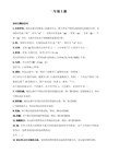
可调谐DFB 激光器
OPEAK OptoElectronics Technology Co., Ltd. Laser center 437, No.6, Keyanxi Road, Nankai District, Tianjin City, 300192 Peoples Republic of China Tel: +8622-87899303/87898266 Fax: +8622-87898266
性能指标
中心波长 最高输出功率 光功率调节范围 功率稳定性 光谱线宽(FWHM) 波长稳定性 波长调谐范围 边模抑制比(SMSR) 相对强度噪声(RIN) 输出端隔离度 工作温度 存储温度 相对湿度 电源功耗 外形尺寸 电源 电气接口 光纤类型 接头类型 尾纤类型
ESD Protection The laser diodes and photodiodes in the module can be easily destroyed by electrostatic discharge. Use wrist straps, grounded work surfaces, and anti-static techniques when operating this module. When not in use, the module shall be kept in a static-free environment.
august2008opeak性能指标参数指标符号最小值典型值最大值单位测试条件中心波长1620nm最高输出功率po20mwpo功率稳定性005db1hr01db8hrs23光谱线宽fwhmbw10mhz1530pm2nmpo边模抑制比smsrsmsr3035相对强度噪声rinrin120dbhz20mhz1ghz输出端隔离度iso3035相对湿度rh15mm电源dcgnd电气接口minidb10型male光纤类型smfpmf慢轴对准接头类型标准配置fcapc型或其它尾纤类型900um松套管长度1mesdprotectionlaserdiodesmodulecaneasilydestroyedelectrostaticdischarge
汽车英语词汇大全(三)
Joggled frame 弯骨架
Joiner 接合件
Joint cross (万向节的)十字头
Joint pin 接合销
Jumper cable 跨接电缆
Jumper hose 跨接软管
Jump seat 折叠式座位
Jump spark 跳跃火花
Lever knob 手把,拉杆
Lever locking device 杠杆固定装置
Lever rod 杠杆,拉杆
Lever spring 变速杆弹簧
Lever spring seat 变速杆弹簧座
Lever switch 杠杆开关
Lever type shock absorber 摇臂式减振器
Kelmet 油膜轴承,铅青铜轴承合金
Kerbing rib (胎侧)防擦线
Key cylinder 锁芯
Deyed-on cam 键装凸轮
Key seater 键槽铣刀
Key way 健槽
Kickback test (转向盘)反冲试验
Kickdown 换低档;自动跳合
Kickdown switch 自动跳合开关
Kick of engine 发动机反转
Kick starter 脚踏起动机
Kick-up of frame 梁架弯曲部分
Kilo 千(SI词头)
Kilocalorie 千卡
Kilogram(me)千克
Leaking point 泄漏点
Leaking valve 漏泄阀
Leak-proof product for radiator 散热器的防漏剂
Leak tester 探漏器
Rigid Endoscope Operating Instructions说明书
RIGID ENDOSCOPEOPERATING INSTRUCTIONSNote: Read this manual first. It contains important instructions and warnings concerning the proper assembly, use, and service of your new rigid endoscopy product(s).IntroductionCongratulations and thank you for purchasing our new rigid endoscopy system! Your new endoscope and surgical instruments was designed and manufactured to the highest quality standards so you may enjoy many years of trouble free service. Each scope was produced using ISO 9002 series standards and is CE 0197 certified.Endoscope Operating & Maintenance InstructionsA) Pre-Op Preparation:1. Physical Damage - Examine the endoscope and accessories for physicaldamage. Cracked or chipped lenses, rough surfaces, sharp edges, bent or loose components should be repaired immediately by a certified factorytechnician prior to use.2. Optics- Examine the optical system in bright light by looking through theproximal end (eyepiece) at the target illustrated below. Position the distaltip of the scope approximately 10mm from each target.¾All surfaces should appear flat, shiny and without distortion. Moisture inside the optical system can cause a cloudy/opaque image or a complete loss of the image.3. Light Transmission- Connect the fiber optic cable to the light post of thescope. The light exiting at the distal tip should be evenly distributedwithout any dark areas, as illustrated below.B) Accessories:Your endoscope is compatible with most accessories that use Karl Storz fittings. The light post is equipped with three universal adapters, as illustrated below. Select the proper connector for your fiber optic light cable.Cautions and Warnings:ENDOSCOPIC PROCEDURES SHOULD ONLY BE PERFORMED BYPERSONNEL TRAINED AND EXPERIENCED WITH RIGID ENDOSCOPY. THE USE OF ENDOSCOPES BY UNAUTHORIZED PERSONNEL MAY LEAD TO INJURY OR DEATH TO THE PATIENT.Endoscopes are fragile optomechanical devices that need to be handled with caution.¾ Always hold the endoscope at the housing body or eyepiece.¾ Do not bend or twist the tubing.¾ Avoid shaking, dropping, or denting the endoscope.¾ Padded telescope cases and plastic shaft guards provide excellent protection against torsional forces and should always be used duringstorage or transport.¾ Due to the high energy from the illumination fiber, do not leave the distal tip in contact with the patient’s tissue. Temperatures may exceed41degrees C (106 degrees F) within a working distance of 10mm.Wolf fitting ACMI connector Storz/Olympus adapter Storz locking cone Removable eyepieceRigid Endoscope Handling and CleaningEquipment Handling:1. Never clean or sterilize the endoscope together with other instrumentsunless these are packaged separately in another container.Cleaning Tips:1. Disconnect the light cable from the light post and remove all cableadapters.2. Soak telescopes immediately after use in a neutral pH enzymatic solution.3. Never soak the instrument in any solution for more than 15 minutes.4. Remove contaminants with a non-abrasive sponge, soft cloth or cottonapplicator soaked in a neutral pH enzymatic solution.5. Remove cleaning solution residue with distilled water and dry with a lint-free cloth.6. Clean all optical elements with alcohol wipes or cotton applicators soakedin 70% alcohol to remove any film or residue. Do not use acetone ormineral spirits.7. Inspect the telescope after cleaning for proper cleanliness and anydamage. Never clean the endoscope in an ultrasonic cleaner Disinfecting / Sterilization:Rigid endoscopes may be disinfected or sterilized using a glutaraldehyde soaking solution of 2.5%. Exposure times should not exceed 15 minutes. After soaking, rinse the telescope well with sterile water and dry with a soft sterile cloth. Pay close attention to the accumulation of residue around the fiber optics at the distal tip and light post. Residue from the disinfectant can form chemical deposits that will decrease light transmission through the fiber optic bundle. Endoscopes NOT marked “autoclave” cannot to be used in temperatures above 60 degrees C (140 degrees F).Autoclaving:Rigid endoscopes bearing the engraving “autoclave” have a duty cycle of 10% and can be steam sterilized up to 134 degrees C (273 degrees F).1. Clean and dry the telescope2. Place the scope in a sterilization tray – allow adequate space around theinstrument to ensure proper circulation and penetration of the steam.3. Autoclave at 134 degree C for three minutes at 2.0 atmospheric pressure.(Do not exceed 5 minutes, 134C at 2.2 bar)4. After the autoclave cycle is complete, remove the container from theautoclave and allow the endoscopes to cool at room temperature for 1hour before removing the top of the sterilization tray.Caution: Repeated autoclaving decreases the life expectancy of the scope due to the stress caused by high heat and pressure. Sudden temperature changes may fracture the optical components. Never cool an endoscope with a sterile liquid or compressed air. Always inspect the instrument after each autoclaving cycle.Liability Statement – Please readPURCHASER UNDERSTANDS AND AGREES THAT THE MANUFACTURER, DISTRIBUTOR, AND RETAILERS OF YOUR ENDOSCOPY INSTRUMENTS ARE NOT RESPONSIBLE OR LIABLE FOR DAMAGE TO EQUIPMENT CAUSED BY THE USE OF THESE PRODUCTS. PURCHASER ALSO UNDERSTANDS THAT HE/SHE USES OUR PRODUCTS AT HIS/HER OWN RISK AND AGREES TO INDEMNIFY, DEFEND, AND HOLD HARMLESS THE MANUFACTURER, DISTRIBUTOR, AND RETAILER FROM ANY AND ALL CLAIMS ARISING FROM THE USE OF SAID PRODUCTS. THIS INCLUDES INJURY TO PATIENTS CAUSED DURING EXAMINATION OR SURGERY AS WELL AS DAMAGE TO MACHINERY, WHICH OUR PRODUCTS ARE INSTALLED. THE PURCHASER ALSO AGREES THAT THE SUBSTANTIVE AND PROCEDURAL LAW OF THE STATE OF CALIFORNIA SHALL GOVERN ANY AND ALL DISPUTES ARISING OUT OF OR RELATING TO THE USE OF OUR PRODUCTS IN ANY WAY. ALL LITIGATION SHALL BE FILED AND SETTLED IN THE FEDERAL AND STATE COURTS OF SANTA CLARA COUNTY, CALIFORNIA USA.WarrantyThe manufacturer warrants each endoscopy instrument to be free from defective material and workmanship for a period of twelve (12) months subjectto the following terms and conditions:The unit is to be delivered by the owner or authorized distributor to the manufacturer intact for examination, with all transportation charges prepaid to the factory, twelve (12) months from the date of sale to the original purchaser. The manufacturer will solely determine when such defect exists.This warranty does not extend to any products, which have been subject to misuse, neglect, accident, improper installation, or used in violation of the operating instructions. Examples of misuse would include but are not limited to the following:¾Bent, curved, dented, or snapped optical tubes.¾Scratched or broken lenses.¾Delaminating of optics caused by excessive heat, extended soaking, or improper use of disinfectants.This warranty does not extend to units that have been repaired, calibrated, or altered in any way by a facility that is not approved, in writing, by the manufacturer to perform such work.This warranty does not apply to any product in which the seals or serial number thereof has been removed, defaced or changed, or to accessories not of our own manufacture.This warranty is in lieu of all other warranties expressed or implied and all such other warranties are hereby expressly excluded. No representative or person is authorized to assume for us any other liability or warranty in connection with the sale of the original manufacturer’s products.Additional information with regard to the applications and maintenance of this equipment will be available from time to time. Please check with your sales person.The manufacturer, distributor, or retailer reserves the right to modify or change the warranty without notice.。
Ojeda CT90商业冷冻器说明书
Ojeda USA, Inc460 Southport Commerce Blvd.Spartanburg, SC 29306864 574-6004 Fax 864 574-6005•••• ••••Part Number 100330039INSTALLATION AND OPERATIONMANUALCT90Congratulations! You have just purchased the finest commercialrefrigeration available.You have selected one of the finest commercial refrigeration units made. It is manufactured under strict quality controls with only the best quality materials available. Your Ojeda cooler, when installed correctly and properly maintained will give you many years of trouble-free operation.Table of ContentsINSTALLATION AND OPERATION MANUAL (1)APPLICATION (3)DIRECTIONS FOR STORAGE AND HANDLING OF THE EQUIPMENT (3)STORAGE OF THE EQUIPMENT (3)UNCRATING (3)MOVING THE EQUIPMENT (4)PLACING AND INSTALLING THE EQUIPMENT (4)ENERGY SAVINGS IDEAS (4)ELECTRICAL REQUIREMENTS (5)PRODUCT LOADING (5)SHELF SPECIFICATIONS (5)UNIT OPERATION (6)POWER FAILURE/FREEZER FAILURE (6)SERVICE CHECKLIST (7)PRESCRIPTIONS, PROHIBITIONS AND OTHER USES FOR THE EQUIPMENT (8)MAINTENANCE GUIDELINES (9)REMOVAL OF FROST (9)CLEANING THE UNIT (9)STANDARD WARRANTY (11)TECHNICAL ASSISTANCE (12)WARNING!U SE THIS APPLIANCE FOR ITS INTENDED PURPOSE AS DESCRIBED IN THIS MANUALWhen using electrical appliances, basic safety precautions should be followed, including the following:∙Use this appliance for its intended purpose as described in this Owner Manual.∙This freezer must be properly installed and located in accordance with the Installation Instructions.∙We strongly recommend that any servicing be performed by a qualified individual. ∙Do not allow children to climb, stand, or hang on the shelves in the refrigerator.They could damage the refrigerator and seriously injure themselves.∙Do not store or use gasoline or other flammable vapors and liquids in the vicinity of this or any other appliance.∙Unplug the freezer before cleaning and making repairs•••• • *****************• Pg. 2 ••••Warning Child Safety!Destroy carton, plastic bags, and any exterior wrapping material immediately after the freezer is unpacked. Children should never use these items for play. Cartons covered with rugs, bedspreads, plastic sheets or stretch wrap may become airtight chambers and can quickly cause suffocation.A child might suffocate if he crawls into a freezer to hide or play. Remove the door of a freezer when not in use, even if you plan to discard the freezer. Many communities have laws requiring you to take this safety precaution.Remove and discard any spacers used to secure the shelves during shipping. Small objects are a choke hazard to children.CAREFULLY READ THESE INSTRUCTIONS. This manual provides instructions in how to best locate, operate, and maintain this equipment.It is recommended to keep this manual for any future reference.APPLICATIONThe CT series of freezers have a sanitation listing permitting the merchandising of packaged food product.PRODUCT REGISTRATIONWrite down the Serial number of your new unit for future reference. The Serial Number is found on the data plate located on the back of the unit.MODEL: ________________________SERIAL NUMBER:_______________DIRECTIONS FOR STORAGE AND HANDLING OF THE EQUIPMENTSTORAGE OF THE EQUIPMENTIf the equipment will be kept in storage, it is suggested to keep it in its original packing.In case you need your equipment to be inactive for a long period of time after being used, verify that it has been unplugged. After cleaning it thoroughly with a damp cloth, lukewarm water and neutral soap and carefully drying it, cover it with a polyethylene film or similar waterproof material.UNCRATINGThe following procedure is recommended for uncrating the unit:Remove the outer package by carefully cutting the banding and removing the cardboard box.Inspect for concealed damage. Immediately file a claim with the freight carrier if there is damage. Move your unit as close to the final location as possible before removing the wooden skid.MOVING THE EQUIPMENTDisconnect the power cord plug from the wall outlet. Remove product, then defrost, and clean the freezer. Secure all loose items such as shelves and fix the door by taping it securely in place to prevent damage. In the moving vehicle, secure the freezer in an upright position and cover it to protect the outside of the cabinet.PLACING AND INSTALLING THE EQUIPMENTT HIS UNIT CANNOT BE INSTALLED IN ENVIRONMENTS WITH EXPLOSIVE GASES.T HE EQUIPMENT ISDESIGNED ONLY FOR INDOOR OPERATION.The unit must be located in an indoor environment.For the correct performance of the refrigerating system, it is very important to leave at least 10 cm (4") of free space both at the sides and back to allow proper air circulation. Do not block the grills on the back of the cabinet.ENERGY SAVINGS IDEASThe location of the cooler must be kept away from sources of heat and humidity including direct sunlight, toasters, ovens, coffee warmers, other appliances condenser air discharge, infrared heaters, or other heat generating appliances.Overloading the freezer forces the compressor to run longer. Do not exceed the load limit according to labels fixed on the inner cabinet.Product to be loaded should be at -4° F (-20° C) since the equipment is intended for maintaining a cool product at 0° F (-18° C) at load level rather than freezing a warm productKeep the lids closed to avoid warm air and moisture getting into the freezer.ELECTRICAL REQUIREMENTSThe power cord of this appliance is equipped with a 3-prong(grounding) plug which mates with a standard 3-prong (grounding)wall outlet to minimize the possibility of electric shock hazard fromthis appliance.The use of extension cords is not permitted and will void thewarranty.Before connecting your equipment, check that the electrical data onthe data plate match your electrical output. If voltage varies by 10percent or more, freezer performance may be affected. Operating thefreezer with insufficient power can damage the compressor. Suchdamage is not covered under the warranty. If you suspect voltage ishigh or low, consult your power company for testing.To prevent the freezer from being turned off accidentally, do not plug unit into an outlet controlled by a wall switch or pull cord.Do not pinch, knot, or bend the power cord in any manner.IMPORTANT NOTICE:P LUG THE EQUIPMENT INDEPENDENTLY TO A LOAD CENTER WITH AN APPROPRIATE CIRCUIT BREAKER ACCORDING TO THE NAMEPLATE AMPS. PRODUCT LOADINGThe CT series of units are not intended to be a pull down freezer and as such the product must be loaded at their intended merchandising temperature.Before loading products, allow the equipment to operate empty for at least four hours.SHELF SPECIFICATIONSThe shelves have been designed to withstand the rigors of normal use. Avoid product overloading to prevent deforming the shelves.UNIT OPERATIONSETTING THE TEMPERATURE CONTROLTo access the temperature control, the rear grill should be removed using a Phillips screw driver.The temperature control is factory pre-set to provide satisfactory product storage products. However, the temperature control is adjustable to provide a range of temperatures for your personal satisfaction. If a colder temperature is desired, turn the control clockwise. Allow several hours for temperature to stabilize between adjustments.POWER FAILURE/FREEZER FAILURENote: Do not open the freezer door unnecessarily if power to the freezer is off for several hoursIf a power failure occurs, frozen foods will stay frozen for at least 2 hours if the freezer is kept closed. If the power failure continues, pack seven or eight pounds of dry ice into the freezer every 24 hours. Cover the product with a cardboard sheet or one inch polyurethane sheet and close the lids. Always wear gloves and use caution when handling dry ice.If the freezer has stopped operating, see "Freezer does not run" in the Service Checklist Section of this manual. If you cannot solve the problem, call an authorized service immediately. Do not allow inexperience people to repair or modify the electrical wiring and/or refrigeration components.SERVICE CHECKLISTBefore calling for service, review this list. It may save you both time and expense. This list includes common occurrences that are not the result of defective workmanship or materials in this appliance. OCCURRENCE SOLUTIONFreezer does not run Check to ensure that freezer is not plugged into a circuit that has ground fault interrupt. If you are unsure about the outlet, have it checked by a certified technician.Temperature control is in the OFF position. See Setting the Temperature Control Section.Freezer may not be plugged in, or plug may be loose. Be sure plug is tightly pushed into electrical outlet.House fuse has blown, or circuit breaker has tripped. Check/reset circuit breaker, or replace fuse with 15 amp. Time delayfusePower outage. Check house lights. Call local electric company.Freezer runs too much ortoo longRoom or outside weather is hot. It is normal for the freezer to work harder under these conditions.Freezer had recently been disconnected for a period of time. Freezer requires 4 hours to cool down completely.Large amounts of warm or hot product have been stored recently. Warm product will cause the freezer to run more until thedesired temperature is reached.Door is kept open too long or too frequently. Warm air enters the freezer every time the door is opened. Open the door lessoften.Freezer door may be slightly open.Temperature control is set too cold. Turn the control knob to a warmer setting. Allow several hours for the temperature tostabilize.Temperatures inside thefreezer are too coldTemperature control is set too cold. Turn the control to a warmer setting. Allow several hours for the temperature to stabilize.Temperatures inside thefreezer are too warmTemperature control set too warm. Turn the control to a colder setting. Allow several hours for the temperature to stabilize.Door is kept open too long or is opened too frequently. Warm air enters the freezer every time the door is opened. Open thedoor less oftenDoor may be open slightly.Freezer has recently been disconnected for a period of time. Freezer requires 4 hours to cool down completely.Temperature of external freezer surface is warm The exterior freezer walls can be as much as 30° F warmer than room temperature. This is normal while the compressor works to transfer heat from inside the freezer cabinet.Sound and noise The fan motor in the compressor compartment is damaged or has a loose connectionLouder sound level whenever freezer is on Modern freezers have increased storage capacity and more even temperatures. They require a high efficiency compressor. When the surrounding noise level is low, you might hear the compressor running while it cools the interior.Louder sound levels when compressor comes on Freezer operates at higher pressures during the start of the ON cycle. This is normal. Sound will level off or disappear as freezer continues to run.Popping or cracking sound when compressor comes on Metal parts undergo expansion and contraction, as in hot water pipes. This is normal. Sound will level or disappear as freezer continues to run.Bubbling or gurglingsound, like water boilingRefrigerant (used to cool freezers) is circulating throughout the system. This is normal.Vibrating or ratting noise Freezer is not level. It rocks on the floor when it is moved slightly. Level the unit.Floor is uneven or weak. Freezer rocks on the floor when it is moved slightly. Be sure floor can adequately support freezer.Level the freezer by putting wood or metal shims under art of the freezer.Moisture forms on insidefreezer wallsWeather is hot and humid, which increases internal rate of frost build-up. This is normal.Door is slightly open.Door is kept open too long, or is opened too frequently.Door is slightly open, causing the cold air from inside the freezer to meet warm moist air from outside.Odor in freezer Interior needs to be cleaned. Clean interior with sponge, warm water, and baking soda.Product with strong odors are in the freezer. Cover the product tightly.PRESCRIPTIONS, PROHIBITIONS AND OTHER USES FOR THE EQUIPMENTThe equipment has been exclusively designed to maintain the proper temperature of packaged food products. Because the unit is not designed to cool the product down quickly, the product must be loaded at its appropriate temperature.Displaying pharmaceutical products in this unit is prohibited.CAUTION- Do not remove grilles or panels that require using tools to be accessed- Do not keep the unit running unloaded. UNPLUG IT when you are not planning to use it.Using any electrical or electronic equipment entails the compliance with some fundamental rules.- Do not touch the unit with wet hands or feet.- Do not install the equipment outdoors.- Do not remove or ignore safety devices.- Do not leave objects on top of the unit.- Do not climb on top of the unit.- Never use direct or indirect water jets on the unit.- Do not allow the electronic control to be adjusted by customers or unqualified personnel.- Under no circumstance should you block the back grille of the unit.THE MANUFACTURER DOES NOT ASSUME ANY RESPONSIBILITY ARISING FROM DAMAGES CAUSED BY IMPROPER, INCORRECT OR ERRONEOUS USE.It is important to instruct the user on the operation of the equipment according to this instruction manual, and to make sure that said manual is within reach of any operator that might use the unit.MAINTENANCE GUIDELINESRegularly and carefully cleaning and defrosting the equipment prevents deterioration and product alteration.REMOVAL OF FROSTIt is recommended to remove the frost accumulated before reloading the freezer or anytime when one quarter inch of frost has accumulated.The unit will have to be manually defrosted. The manual defrost frequency will depend on the units usage, environment, and the amount of frost accumulated.1.Make sure the unit is moved close to a floor drain or a means of collecting or containing thewater is used.2.Unplug the unit until all the frost is gone.3.When the ice has melted wipe up any water left on the freezer floor.4. Allow the freezer to refrigerate and cycle before placing the product back into the freezerTo defrost while keeping the freezer plugged in place a clean dry soft cloth over the product to catch the frost that will be removed. Remove the frost using a plastic scrapper trying to eliminate as much frost as possible.CLEANING THE UNITWash any removable parts, the freezer interior, and exterior with mild detergent and warm water. Wipe dry. DO NOT USE HARSH CLEANERS ON THESE SURFACES. Do not use razor blades or other sharp instruments, which can scratch the appliance surface.Cleaning the InsideWARNING!D AMP OBJECTS STICK TO COLD METAL SURFACES.D O NOT TOUCH THE INTERIOR METAL SURFACES WITH WET OR DAMP HANDS.After defrosting, wash the inside surfaces of the freezer with a solution of two tablespoons of baking soda in one quarter of a gallon(1.1 liters) warm water. Rinse and dry. Wring excess water out of the sponge or cloth when cleaning in the area of the controls, or any electrical parts.Wash the removable parts and door with the baking soda solution, or mild detergent and warm water. Rinse and dry. Never use metallic scouring pads, brushes, abrasive cleaners, or alkaline solutions on any surface. Do not wash removable parts in a dishwasher. Do not shower water with a hose nor use ammonia based cleaners.W ARNING T HE LOWER SIDE OF THE GLASS LIDS IS PROVIDED WITH A SPECIAL FILM.D O NOT USE RAZOR BLADES OR OTHER SHARP INSTRUMENTS WHICH CAN SCRATCH THIS SURFACE AND DAMAGE THE FILM.Cleaning the OutsideWash the cabinet with warm water and mild liquid detergent. Rinsewell and wipe dry with a clean soft cloth. Do not shower waterwith a hose nor use ammonia based cleaners.Clean every week with only a damp piece of cloth and neutral soapeach external and internal surface, and dry them with a clean softcloth.Never use flammable or abrasive products. The unit must never becleaned with water jets.IMPORTANT: During maintenance and cleaning operations, makesure that good visibility conditions exist in the working area, usingother light sources in case it is needed. Be very careful whenworking with moving and/or high-temperature parts.STANDARD WARRANTYCT90 COUNTER TOP FREEZEROjeda USA INC. warrants to the original purchaser of an CT90, that the cabinet and all of its parts be free of defects in material and manufacture under normal use and service for a period of 1 year from the date of shipment to the original purchaser.Ojeda USA shall for the first 1 year of the above warranty, provide and pay for reasonable straight time labor charges to install the named parts. After such year, no labor or costs shall be provided free of charge.The compressor part is covered for a total of 5 years from date of shipment.An Authorized Service Agent must perform Ojeda USA’s obligations for service and parts under the warranty. The user must give the Authorized Service Agent prompt notice when service is needed.The sealed refrigeration system is limited to repairing and replacing at Ojeda USA’s option any component with a similar component when, upon our examination and to our satisfaction, it is determined to be defective.This warranty only applies to Ojeda CT90 COUNTER TOP FREEZER when operated in normal conditions and with electrical power supplies as indicated on the serial plate (115 Volts 60 Hertz). The warranty is voided when the serial number is missing or when a unit or any part has been subject to defacing, vandalism, misuse, neglect, alteration without proper authorization, accident or damage caused by transportation, flood, civil disorder, fire, or any other actions beyond the control of Ojeda USA Inc.Standard warranty does not cover glass and frame, lamps or light bulbs.Standard warranty does not cover loss or spoilage of food or any other contents of the cabinet. The Standard Warranty shall apply only within the boundaries of the continental United States and Canada.Effective January 1, 2007•••• • *****************• Pg. 11 •••••••• • *****************• Pg. 12 ••••Part Number 100330039TECHNICAL ASSISTANCEIf technical personnel assistance is required, you must immediately contact your distributor, specifying the kind of problem and clearly indicating the equipment model and serial number. If replacing parts is required, do it through your distributor.WARNING: Always ask for original spare partsAUTHORIZED DISTRIBUTOR:_____________________________________COMMERCIAL NAME:_____________________________________ADDRESS:_____________________________________TELEPHONE:_____________________________________E-MAIL:_____________________________________。
模块化轻型FRL气囊调节器套件说明书
Popular combinations1/4" FRL Combinations5 micron elements, 8 bar regulator + gauge and wall mounting bracketsOptions:PortsBowl - DrainFlow @ 6 bar G 1/4P3D-CB12BGB P3D-CB12CGB P3D-CB12KGB P3D-CB12LGB 120020G 3/8P3D-CB13BGBP3D-CB13CGBP3D-CB13KGBP3D-CB13LGB120020Transparent Bowl Transparent Bowl Metal Bowl Metal Bowll/min dm 3/s Manual DrainSemi -Auto Drain Manual Drain Semi-Auto Drain P3D-CB12BGBPopular combinationsFilter/Regulator - Lubricator Combinations5 micron elements, 8 bar regulator + gauge and wall mounting bracketsOptions:PortsBowl - DrainFlow @ 6 bar G 1/4P3D-CA12BGB P3D-CA12CGB P3D-CA12KGB P3D-CA12LGB 130021.7G 3/8P3D-CA13BGBP3D-CA13CGBP3D-CA13KGBP3D-CA13LGB130021.7Transparent Bowl Transparent Bowl Metal Bowl Metal Bowll/min dm 3/s Manual DrainSemi -Auto Drain Manual Drain Semi-Auto Drain P3D-CA12BGBPopular combinationsFilter/Regulator and Ball valve combinations with wall mounting brackets and port connectors, 5µ element,8 bar secondary pressureOptions:Ports PressureMetal BowlTransparent bowl Flow @ 6 bar max, bar ManualSemi-Auto ManualSemi-Autol/min dm 3/s G 1/417P3D-AN12KGB P3D-AN12LGB 110018.3G 3/817P3D-AN13KGBP3D-AN13LGB138023G 1/410P3D-AN12BGB P3D-AN12CGB 110018.3G 3/810P3D-AN13BGBP3D-AN13CGB138023P3D-AN12KGBPopular combinationsDump valve and soft start valve combinations with wall mounting bracketsPorts Pilot operated dump valve + manual set point soft start valvel/min dm 3/s G 1/4P3D-CS12QMB 250041.7G 3/8P3D-CS13QMB250041.7Ports Solenoid operated dump valve + manual set point soft start valveFlow @ 6 bar 24V DCValve without Solenoid l/min dm 3/s G 1/4P3D-CS12GMB2CC P3D-CS12GMB000250041.7G 3/8P3D-CS13GMB2CCP3D-CS13GMB000250041.7Valves other than 24 V DC to be purchased less solenoid and solenoid ordered separately.Options:P3D-CS12QMSOptions:FiltersSymbolsFilter element grade:Standard 5 micron Option 40 micronFlow @ 7 bar 1200 l/min - G 1/8 20 dm 3/s Inlet 0.7 bar 1980 l/min - G 1/4 33 dm 3/s pressure drop 2760 l/min - G 3/8 46 dm 3/s Pressure range:10 bar max Nylon bowl 17 bar max Metal bowlTemperature range:-10OC to +50O C Nylon bowl -10O C to +75O C Metal bowl Weight (g)276g Nylon bowl without port blocks450g Metal bowlTechnical informationDimensions (mm)Choice of transparent nylon or metal bowls with convex integral sight glasses.Quick release bowl mechanism - added safety, bowl cannot be removed whilst pressurised.Sight glass can be located in 900 increments.Elastomatic filter elements shrug off larger dirt particles as flow varies.5 micron elements as standard, option 40 micron.No tools required for dismantling or cleaning element -routine servicing without removing from line.Manual drain Semi auto drainFor accessories and port blocks see page 37.For Repair Kits and Spares see page 62 and 63.G 3/8G 1/4G 1/80,10,20,30,40,50,60,7P r e s s u r e d r o p (b a r )Air flow l/s at 7 bar inlet1020304050Flow characteristicsOptions:Coalescing filters and AdsorbersRemoves oil and water aerosols.Maximum oil carry over 0.02 mg/m 3All units interchangeable and removable without disturbing pipework, by simply unscrewing retaining screws.Captive retaining screws automatically realign and reseal units when refitting.Coalescing filtersRemoves hydro-carbon vapours.Removes oil vapour carry-over.Activated carbon element.For breathable air applications.Maximum oil carry over 0.005 mg/m 3AdsorbersFor accessories and port blocks see page 37.For Repair Kits and Spares see page 62 and 63.RegulatorsSymbolsGauge port sizeG 1/8Maximum inlet pressure 20 bar maxFlowSee performance characteristics Secondary pressure rangeLow 0,2 to 2 bar max Low 0,2 to 4 bar max Medium 0,4 to 8 bar max High 0,4 to 16 bar max Temperature range -10OC to +75O C Weight (g)330without port blocks Technical informationDimensions (mm)One balanced, self relieving, diagram operated unit for all flows and combinations - optional non-relieving unit available.Simple push to lock non-rising adjustment knob with low operating torque; easily tamperproofed.Panel mounting ring available.Excess secondary pressure relieves at low differential.Four secondary pressure ranges available, with colour coded adjustment knobs.16 bar Orange, 8 bar Black, 4 bar Grey, 2 bar BlueOptions:5,4For accessories and port blocks see page 37.For Gauges see page 61.1234567S e c o n d a r y p r e s s u r e (b a r )8Air flow l/s at 7 bar inlet246810121234567S e c o n d a r y p r e s s u r e (b a r )Air flow l/s at 7 bar inlet1020304050Flow characteristicsRegulation characteristicsRegulator angle bracketSelf bleed regulator with gaugeNon bleed regulator1Filter/Regulators Symbol21Gauge port size G1/8Maximum inlet pressure Metal bowls17 bar maxNylon bowls10 bar maxSecondary pressure range Low0,2 to 2 bar maxLow0,2 to 4 bar maxMedium0,4 to 8 bar maxHigh0,4 to 16 bar max*Filter element grade Standard 5 micronOption40 micronTemperature range-10O C to +50O C Nylon bowl-10O C to +75O C Metal bowlTechnical information Dimension (mm)Options:Choice of metal bowl with convex sight glass ortransparent nylon bowl.Elastomatic filter elements shrug off larger dirt particlesas flow varies.5 micron element as standard, option 40 micron.One balanced, self relieving, diagram operated unit forall flows and combinations - optional non-relieving unitavailable.Simple push to lock non-rising adjustment knob with lowoperating torque; easily tamperproofed.Four secondary pressure ranges available, with colourcoded adjustment knobs.16 bar Orange, 8 bar Black, 4 bar Grey, 2 bar BlueFor accessories and port blocks see page 37.For Gauges see page 61.For Repair Kits and Spares see page 62 and 63.For performance graphs see Regulator page 27.Pressure range:10 bar max Nylon bowl 17 bar max Metal bowlTemperature range:-10O C to +50O C Nylon bowl -10O C to +75O C Metal bowlFlowSee performance characteristics Weight (g)286g Nylon bowl without port blocks456g Metal bowl Minimum flow for oil pick up 0,25 dm 3/s Bowl capacity55 cm 3Recommended lubricants See page 63LubricatorsSymbolsLubricatorLubricator with dr ainOptions:Technical informationDimensions (mm)Choice of transparent nylon or metal bowls with convex integral sight glasses.Quick release bowl mechanism - added safety bowls cannot be removed whilst pressurised.Sight glass can be located in 900 increments.Constant density lubrication with fingertip adjustment.Low flow oil pick up capability.3600 drip rate sight glass gives all round visibility,contained in separately serviceable cartridge.187654321P r e s s u r e d r o p (b a r )Air flow dm 3/sec at 7 bar inletG 1/4G 3/824681012141618202224For accessories and port blocks see page 37.For Repair Kits and Spares see page 62 and 63.Flow characteristicsModular Junior FRLsThe controlled introduction of pressure can be animportant safety factor and prevent damage to tooling etc.when air pressure is introduced at machine start up.The soft start valve is an ideal method of providing a fully adjustable controlled introduction of pressure.Soft Start Valve Operation:The switch point is set via the control knob and is fully adjustable between 1 and 5 bar. Additionally the bleed orifice which delays the rise in pressure is supplied as standard in several diameters:-Ø1,5mm, Ø2,2mm, Ø3mm, and Ø3,8mm.These are field interchangeable by removing the top plug of the valve.Effect of orifice on flow characteristics of pneumatic switch (with 1.5mm bleed orifice)Flow characteristics for ('Soft Start' valve)Typical combinationsFig. 2.Fig. 2. shows the Soft Start and Dump valve assembled as part of the main 1/4" Modular FRL combination feeding an entire system.Fig.1. enables part of a system to be isolated and the air dumped to atmosphere whilst operating another part normally.dump valveThe soft start valve will, when set, allow the pressure to gradually build to the set point before fully opening to deliver full flow at line pressure.In normal operation the soft start valve is assembled, in series, with an accompanying air pilot, solenoid pilot or manually actuated dump valve. This is used as an on - offswitch for line pressure, and for exhausting the system.1234567896080705040302010Time secs.10 seconds I n l e t p r e s s u r e 10 b a r10 bar inlet A 1 to 3 turns 10 litre volumeB 4 turnsC 5 turnsD 6 turnsE 7 turnsF 8 turns123456102030405060708090P r e s s u r e d r o p (b a r )Flow (dm 3/s)Modular Junior FRLsSoft Start ValvesSymbolManually operatedControlled induction of pressure Fully adjustable switch pointMax. inlet pressure 10 bar max.Temperature range -100C +500CFlow @ 6 bar 2500 l/min - 41.7 dm 3/sWeight428gTechnical informationNote:For materials see page 34.Options:DimensionsModular Junior FRLsRemotely Operated Dump ValvesSymbolAir pilot or solenoid pilot operated dump valves Low Watt solenoid coilsValves for other than 24 V DC to be purchased less solenoid & solenoid ordered separately.OperationRemotely operated dump valves automatically shut off upstream pressure and exhaust the downstream pressure when the pilot pressure is released.To maintain these units in the open position a pilot supply to the air pilot operated version or an electrical signal to the solenoid operated version mist be maintained.The valve will automatically dump when the holding signal is removed.Max. inlet pressure 10 bar max.Temperature range -100C +500CFlow @ 6 bar Through valve to exhaust2500 l/min - 41.7 dm 3/s 2000 l/min - 33.3 dm 3/s Weight484g Technical informationNote:For materials see page 34.Options:DimensionsMuffler included with each product.Modular Junior FRLsManually Operated Dump ValvesSymbolMax. inlet pressure 10 bar max.Temperature range -100C +500CFlow @ 6 bar Through valve to exhaust 2600 l/min - 43.3 dm 3/s 2800 l/min - 46.7 dm 3/s Weight360gTechnical informationNote:For materials see page 34.Options:DimensionsMuffler included with each product.Flow characteristics:Secondary to exhaustFlow characteristics:Inlet to secondaryShuts off upstream and dumps downstream pressure.Choice of red or black knobs.G 1/8, G 1/4 or G 3/8 ports.Ventral G 1/4 exhaust port.Padlockable version.2 position or latching versions.MONOSTABLE version . 2 exhaust dump functionsManually, by maintaining the button thrust down during time required to dump the downstream pressure.Automatically, when the upstream pressure falls below the set pressure threshold.To reset, effective upstream pressure and a manual lift of the knob is required.MONOSTABLE dump valves are an important element inmachine safety considerations. After a unexpected upstream pressure failure, e.g compressor break down), system pressure reset will be only be obtained by lifting the knob combined with having an effective upstream pressure.BISTABLE versionThe dumping of downstream pressure is manually actuated by depressing the knob.To reset, both effective upstream pressure and a manual lift of the knob is required.Solenoids for Soft Start and Dump ValvesSolenoids for Dump Valves (CNOMO solenoid)Supplied with cable plug and non-locking overrideSolenoids for Dump Valves (15mm solenoid)Supplied with cable plug and non-locking flush manual overrideLarge headed screw forinaccessible or recess positionStandard to be wired universal P8C-C To be wired LED+protection 24 VDC P8C-C26C With standard screwStandard to be wired universal P8C-D To be wired LED+protection 24 VDC P8C-D26C With cable and standard screw Standard with 2 m cable P8L-C2Standard with 5 m cableP8L-C5LED+protection 24 VAC/DC, 2 m P8L-C226C LED+protection 24 VAC/DC, 5 mP8L-C526CCable plugs 15 mm (8 mm pin spacing) IP 65DescriptionOrder codeDescription Order code Cable plug, for CNOMO solenoid 24V, LED+Diode9125 9980-0424V AC/DC, LED+VDR 9125 9980-06110V AC/DC, LED+VDR 9125 9980-08240V AC/DC, LED+VDR 9125 9980-10Black451BVoltageOrder code CNOMO-SolenoidsModular Junior FRLsBodies ZincHousingsAluminium Fixing Screws Plated Steel KnobsAcetal Valve StemsBrassSSV Main Spring Plated Steel Springs Stainless Steel SealsNitrile Body Connectors Zinc Port BlocksZincAccessory ProductsBodyZincFixing Screws Plated Steel Bowl (metal)ZincBowl (transparent)Polyamide Sight Glass Polyamide KnobAcetal Venturi Valve Acetal Transfer Tube Nylon Tube Retainer BrassSprings Stainless Steel Seals NitrileFill PlugAluminiumLubricatorMaterials BodyZincFixing Screws Plated Steel Bowl (metal)ZincBowl (transparent)Polyamide Sight Glass Polyamide Louvre Acetal ElementNylon 6Manual Drain AcetalSemi-Auto Drain Acetal / Brass Springs Stainless Steel SealsNitrileFilterBodyZincFixing Screws Plated Steel Control Knob AcetalAdjusting Screw Plated Steel Spring Rest (upper)BrassSpring Rest (lower)Steel / Brass SpringPlated Steel Diaphragm Nitrile / Nylon Valve Stem Brass Valve Seat Nitrile Bottom Cap AcetalSprings Stainless Steel SealsNitrileRegulatorConnection Pressure Actuation Note Weight Order code Flow @ 6 barmax, bar Kg l/min dm 3/sUpstream 10Hand Standard 0,230P3D-VA00A0N 140023.3Downstream 10Hand Standard 0,230P3D-VA00B0N 140023.3Upstream 10Hand 3 Padlock Facility 0,255P3D-VA00P0N 140023.3Downstream 10Hand 3 Padlock Facility 0,255P3D-VA00R0N 140023.3Upstream10Hand 6 Padlock Facility 0,260P3D-VA00Q0N 140023.3Downstream10Hand6 Padlock Facility0,260P3D-VA00S0N140023.3Junior Modular Ball ValveNote! Modular Ball valves have an integral body connector on one side and a slot to accept a port block or body connector on the other.Note! Cannot be used separately.SymbolPositive bubble tight shut-off.Upstream and downstream versions.Padlockable version.Ventral G 1/4 exhaust port.Modular Junior FRLsDimensionsAll dimensions in (mm).The modular system ensures constant mounting centres;assemblies are fixed to the special wall brackets by a single fixing screw.Filter, Regulator, Lubricator Filter/Regulator, LubricatorBall Valve +Filter/RegulatorModular Junior FRLsMounting assembliesAssembly containing a regulator or filter regulator Assembly without regulator or filter regulatorWall brackets mounted at the ends of an assembly Wall brackets mounted at the ends of an assemblyNeck mounting bracket on Filter/Regulator Popular combination with wall mounting bracketsPneumatic output Adjustment GaugeindicatorPneumatic push buttonpanelPressure taken upstream of the ARPSAdjusting the cut-off pressureTamper-proof sealing plugAdjustment by allen key (H6)On all ARPS, the tripping pressure is adjusted by an allen key. T amper proof sealing plug prevents unauthorised adjustment.Adjustable Reset Pressure SwitchesModular FRLsPressure gauges Modular FRLsFilter Spare Kits Mini SeriesJunior SeriesMaxi SeriesG1 Series ModelP3AP3DP3EP3NDrain KitsManual drain kit P3E-KA00DBN P3E-KA00DBN P3E-KA00DBN P3E-KA00DBN Semi-auto drain kit P3A-KA00DCNP3A-KA00DCNP3A-KA00DCN P3A-KA00DCN Auto drain kitP3E-KA00DDNP3E-KA00DDNBowl Kits Poly bowlPoly bowl with manual drain P3A-KA00BBA P3D-KA00BBA P3E-KA00BBA Poly bowl with semi-auto drain P3A-KA00BCAP3D-KA00BCAP3E-KA00BCA Poly bowl with auto drainP3E-KA00BDAMetal bowlMetal bowl with manual drain P3A-KA00BPA P3D-KA00BKA P3E-KA00BKA Metal bowl with semi-auto drain P3A-KA00BQAP3D-KA00BLAP3E-KA00BLA Metal bowl with auto drainP3E-KA00BMA Compact metal bowl with manual drain P3E-KA00BTA Compact metal bowl with semi-auto drain P3E-KA00BVA Compact metal bowl with auto drainP3E-KA00BWAFilter Element Kits5 micron elementP3A-KA00EENP3D-KA00EENP3E-KA00EEN P3NKA00ESE5 micron element (compact bowl)P3E-KA00ERN 40 micron elementP3A-KA00EGNP3D-KA00EGNP3E-KA00EGN P3NKA00ESG 40 micron element (compact bowl)P3E-KA00ESN Coalescing elementP3A-KA00ECNP3D-KA00ECNP3E-KA00ECN P3NKA00ESC Coalescing element (compact bowl)P3E-KA00EPN Adsorber elementP3A-KA00EANP3D-KA00EANP3E-KA00EAN P3NKA00ESA Adsorber element (compact bowl)P3E-KA00ENNSeal KitsPoly bowl seal (10 off)P3A-KA00RZN P3D-KA00RWN P3E-KA00RZN Metal bowl seal (10 off)P3A-KA00RZN P3D-KA00RWN P3E-KA00RWN Connector O ring (10 off)P3A-KA00CYNP3D-KA00CYNP3E-KA00CYNSpares and Replacement PartsModular FRLsRegulator Spare KitsRepair kit (self-relieving)P3D-KA00RRN P3E-KA00RRN P3NKA00RR Repair kit (non-relieving)P3D-KA00RNN P3E-KA00RNN P3NKA00RNMetal panel mounting ring P3A-KA00MMN P3A-KA00MMN P3E-KA00MMNPlastic panel mounting ring (5 off)P3A-KA00MPN P3A-KA00MPN Tamperproof kitP3A-KA00ATNP3A-KA00ATNP3E-KA00ATNSpares and Replacement Parts Modular FRLsMini Series Junior Series Maxi Series G1 Series Model P3A P3D P3E P3NFilter/Regulator Spare Kits5 micron element P3A-KA00EEN P3D-KA00EFA P3E-KA00EFA P3NKA00ESE5 micron element (compact bowl)P3E-KA00ETA40 micron element P3A-KA00EGN P3D-KA00EHA P3E-KA00EHA P3NKA00ESG40 micron element (compact bowl)P3E-KA00EVARepair kit (self-relieving)P3D-KA00RRN P3E-KA00REN P3NKA00RR Repair kit (non-relieving)P3D-KA00RNN P3E-KA00RGN P3NKA00RN Tamperproof kit P3A-KA00ATN P3A-KA00ATN P3E-KA00ATNFor Drain Kits - see Filters on page 62For Bowl Kits - see Filters on page 62For Bowl Seal Kit - see Filters on page 62Lubricator Spare KitsPlastic bowl without drain P3A-KA00BAA P3D-KA00BAA P3E-KA00BAAFor Manual Drain Kits - see Filters on page 62For Bowl Kits with Manual Drain - see Filters on page 62For Bowl Seal Kit - see Filters on page 62Lubrication of airlinesSatisfactory operation of airline equipment and effective lubrication depends upon the proper selection of lubrication oil. Oils havinga viscosity below ISO3448 Grade 10 to 22 will satisfy most high-speed pneumatic tools and other light duty requirements.Heavy duty tools and pneumatic valves and cylinders will normally require oils in the viscosity ISO3448 Grade 32 to 68.Only Paraffinic based oils can be used and the following recommendations are given as a general guide to types of oil that aresuitable for use with Parker airline equipment.High speed tools and systems Air Cylinders and valves Oil Company ISO Grade Grade ISO Grade GradeCentury Oils Century P - 19815P.W.L.A32Alexander Duckham Zurcon 215Zurcon 4 32Gulf Harmony 38AW15Harmony 43AW32Shell (UK) Oil Tellus 2222Tellus 3737Burmah Castrol Hyspin AWS1515Hyspin AWS3232Edgar Vaughan KSO 5L10Hydrodrive HP10032Esso Petroleum NUTO 111515NUTO H3232B.P.HLP 2222HLP 3232Mobile Oil Company Velocite No.610DTE Oil - Light32Mobile VPI-A32Silkolene Silkair GP2222Derwent 3232Silkolene Dove 1515Most Parker Pneumatic valves and cylinders are designed for use in non-lube operation. However airline lubrication will increase the service life.Note! If oil lubrication is used, it must be maintained for the service life of the product.Some specialised lubricants, particular synthetic reclaimed oils and low temperature additives, may contain compounds which are incompatible with certain materials, internal ‘O’ rings and seals. They may also attack plastic piping or the transparent bowls of the airline lubricator. Attention is drawn to BS6005 (Specification for moulded transparent polycarbonate bowls used in compressed air filters and lubricators).Do not use oils with ad ditives, compounds oils containing solvents, graphite, detergents or synthetic oils.Modular Junior FRLs AccessoriesDescription Connection Weight Order codeKgPort connector kits G1/80,150P3D-KA11CPN Array (2 port blocks + 2 seals)G1/40,150P3D-KA12CPNG3/80,150P3D-KA13CPN。
汽车专业英语词汇
引擎机动力改装部分:进气管==Intake空气过滤器==冬菇头==air filter排气管==尾喉/死气喉==Exhause消音器==mufeler机油冷却器==oil cooler火花塞==火嘴==spark plug火嘴线==spark plug wires阀门==滑老==valve滑轮==pully活塞==piston曲轴==crankshaft凸轮轴==cam shaft气门弹簧==滑老弹弓==valve spring涡轮增压==turbo charger机械增压==super charger中冷==inter cooler放气阀门==放气滑老==blow-off valve废气阀门==wastgate压力控制器(怎么也想不出个的翻译)==水喉制==boost controller喷油嘴==大唧咀==Injector头批==down pipe行车电脑==ECU制动悬挂部分:轮圈==车伶==Rim刹车碟==迫力碟==rotor活塞卡钳==鲍鱼==caliper刹车片==迫力皮/来令片==brake pad避震==suspention(避震分为弹簧/弹弓==spring 和减震桶==shock 两部分)整套避震又叫coilover波子塔顶==Pillow Ball Top Mounts防倾杆==sway bar用在车里的加强杆==tower bar用在车底的加强杆==lower arm bar传动部分:末齿比==大尾牙==Final Drive差速器==LSD离合器==极力子==clutch飞轮==flywheel车身部分:大包围==bodykit(车头==front bumper, 车尾==rear bumper, 车别裙==side skirt)尾翼==sopiler车头盖==hood (两种不同材质:碳纤维==carbon fiber, 玻璃钢==firberglass)(engine type) liquid cooled, in-line, 4cylinder, carb (发动机型号)水冷,直列,四缸,化油器式(engine) compression ratio (发动机)压缩比(engine) displacement (发动机)排量(engine) fuel (发动机)燃料13-mode 13工况3rd gear 三档齿轮3-way seat 三向座椅4WD control device 四轮驱动控制装置4WD indicator switch 四轮驱动指示灯开关4WD lamp electrical connection 四轮驱动指示灯接线4WD switch 四轮驱动开关5th synchromesh assy. 五档同步器总成6PK belt 6PK 多楔驱动皮带A / C compressor assembly 空调压缩机总成A / C control assembly 空调控制装置A/C & heater assy. 空调加热器总成A/C blower 空调鼓风机A/C clutch 空调压缩机离合器A/C compressor MTG bracket 空调压缩机安装支架A/C control assy. 空调控制器A/C housing assy. 空调箱总成A/C low pressure switch 空调低压开关A/C mode select switch 空调状态选择开关abdomen performance criterion 腹部性能指标Abdominal Peak Force 腹部力峰值ABS 防抱死制动系统acceleration fuel system 加速系统acceleration running noise level 加速行驶噪声accelerator interlocking type 加速踏板联锁式accounting foundation 财政基础Actual cycle work 实际循环功Actual torso angle 实际躯干角adapter 连接器additional features 附加装置additional rule 附加法规adjust screw 调整螺钉adjuster cable 调整拉线adjuster plug 调整盖adjuster screw assy. 调整螺栓总成adjuster washer 调整棘片adjuster, diff. bearing 差速器轴承调整螺母Adjustment system 调节装置Administration and Registration Division 管理科Agreement Concerning the Adoption of Uniform Technical Prescriptions for Wheeled V ehicles, Equipment and Parts Which Can Be Fitted and/or Be Used on Wheeled Vehicles and the Conditions for Reciprocal Recognition of Approvals Granted on the Basis of These Prescriptions 关于对轮式车辆、安装和/或用于轮式车辆的装备和部件采用统一条件并相互认可基于上述条件批准的协定书Agreement Regulations 协定法规air cleaner 空气滤清器air cleaner assy. 空气滤清器总成air cleaner cartridge 空气滤清器滤芯Air compressor 空压机air condition compressor 空调压缩机air direct 空气走向air filter 空气滤清器air flow 空气流向Air flow meter 空气流量计air jet 空气量孔air metering hole 空气量孔air path 气道Air Pressure of Tire 轮胎气压Air type 空气型air valve 空气阀air-cooled 风冷Aisles 通道Alcohol 酒精all bearing 球轴承alternater bracket 发动机支架alternator 交流发电机alternator assembly 交流发电机总成alumininum-rim 铝合金钢圈alumininum opposed model 铝制对开式AM/FM cassette stereo radio 调幅/调频立体声收放机ambulance 救护车Amended by 修正文amount of exhaust emission 排气排放量Amplitude resolution 幅度分辨率Analogue magnetic recorder 模拟式磁记录仪ANAL YZER 分析仪anchor plate, brake caliper 制动钳安装支架Anchorage 座椅固定装置Angle of divergence 偏离角Angle of rotation 旋转角angles drift off vertical line 指针偏离垂直线的角度Angular diameter of the retro-reflecting device 回复反射装置的角直径annex 附件Announcement 公告anti, shutdown screw 防不灭车调整螺钉Antilock Brake System 防抱死制动系统appendix 附录Applicable motor vehicle 适用机动车Applicable scope 适用范围applicant 申请人application 申请application for notification 认可申请书approval 认可arm, valve rocket 摇臂armature 转子总成armature shaft 电枢轴Arm-rests 靠手Article 条Article 1 第1条Asphalt solution 沥青溶剂Attached document 附署文件attached sheet 附表Attached Table 附表attaching location of seat belt anchorage 座椅安全带固定装置的固定位置attachment 附属文件Attendants onboard 车上值班人员automatic chock cover setting 自动阻风门盖调到automotive electric system 汽车电系automotive engine system 引擎系统automatic transmission 自动变速器,自动排挡变速箱Auxiliary Brake 辅助制动器Auxiliary Direction Indicator Lamps 辅助转向信号灯auxiliary spring 副簧Auxiliary Stop Lamp 辅助驻车灯axle case 桥壳axle case assy. 桥壳总成axle ratio 桥速比axle tube 桥管axle weight 轴重back angle level 靠背角水平仪back angle quadrant 靠背角量角器back pan 靠板back spring 回位弹簧backing plate 制动底板Backing sheet 衬背板Back-Up Light 倒车灯backup washer 支撑挡圈bail wire 卡紧环balance tube 平衡管ball 钢球ball bearing 球轴承ball joint assy. , upper 上球销总成ball valve 球阀ball valve, inlet 进油口球阀bar 拉杆barrier 障碍壁battery 蓄电池battery terminal 蓄电池接线柱bearing cap 轴承盖bearing cover, input shaft 输入轴轴承盖bearing, connecting rod 连杆轴承bearing, input shaft 输入轴轴承Bed for babies 婴儿床bell 带束层bench seat 长条座椅berived cap 轴承盖bezel assy. 框板总成bezel, cluster 表框be pilot 小批量产品blead door 混合风门bleeder screw 放气螺钉blower assy. 鼓风机总成blower motor 鼓风发电机blower resistor 鼓风机电阻blower switch 鼓风机开关body 车身,阀体body & liftgate assembly 车身和举升门总成body assy. 车身总成body block 人体模块body of A/C & heater 空调加热器壳体bolt 主缸连接螺栓bolt, connecting rod 连杆螺栓Booster 助力器boot 护罩BOSCH starter motor assembly “波舍”起动机总成bottle assy. , coolant recover 冷却液回收罐总成bottom houseing, fuel pump 燃油泵下壳体bottom housing, fuel tank 燃油箱下壳体bracket 支架bracket assy. , spring seat 弹簧座支架bracket, steering damper mounting 转向减振器支架brake alarm lamp 制动报警灯brake alarm lamp switch 制动报警灯开关Brake booster 制动助力器brake caliper 制动钳brake caliper assy. 制动钳总成brake caliper piston 制动钳活塞brake combination valve 制动组合阀brake disc 制动盘Brake drum 制动鼓brake fluid 刹车油Brake hose 制动软管brake lining 刹车来令brake line, LF 左前制动油管brake line, RF 右前制动油管brake oil flow 制动液流向brake paddle 制动踏板brake pedal 制动踏板Brake pipe 制动管brake shoes 刹车蹄片brake shoe 制动衬块Brake System 制动系Brake Systems for Tractors and Trailers 牵引车及挂车的制动装置Brake tester 制动器试验台brake valve 制动阀brake warning lamp 制动报警灯brake warning switch 制动报警开关Braking efficiency 制动效能braking force control system 制动控制装置Braking wheel 制动轮branch office 分署breaker 断电器bridge 过桥broadcasting vehicle 广播车brush 碳刷总成Buckle 带扣bulkhead 隔板Bulldozer 推土机bumper 保险杠Bumper element 保险杠构件bus transfer 车辆转移台bushing 衬套bushing, upper control arm 上控制臂衬套Business Place 业务场所bypass valve 旁通阀Cabinet Decision 内阁决议cable guide 拉线导向块cable-operated control system 液压式离合器系统Calibration factor of a data channel 数据通道校正系数calibration gas 标定气体calibration method 标定方法caliper assy. , front brake 前制动钳总成Camber 外倾camber angle 前轮外倾角camshaft 凸轮轴camshaft oil gallery 凸轮轴油道cap 加机油口盖cap assy. , power steering fluid reservoir 动力转向液油罐盖cap assy. , radiator 散热器盖总成cap screws 螺钉cap, connecting rod 连杆盖Capacity 容量,规格Capacity of the fuel tank 燃油箱容量capillary tube 毛细管carbon brushes & brush holder 电刷支架总成Carbon monoxide measuring instrument 一氧化碳分析仪Carburetor 化油器carburetor assy. 化油器总成carburetor bowl 化油器浮子室carburetor bowl vent system 化油器浮子室通风系统carburetor overhaul scheme 化油器分解图carburetor working scheme 化油器工作示意图carcase 胎体case runout (Max.) 差速器壳圆跳动(最大)Caster 后倾Catalyst 催化器category 类别cement and aggregate 水泥和混凝料Centreplane of occupant 乘员中心面Certified 经认证的Cetane number 十六烷值chain 驱动链chain drive 驱动链Channel amplitude class 幅度级通道Channel Frequency Class 频率级通道chassis 底盘chassis dynamometer 底盘测功机chassis shuttle 底盘平移台chassis number 底盘号Check and Maintenance 检查和保养check assy. , front door 前门限位器总成check assy. , rear door 后门限位器总成check ball 回止球check bracket 限位器支架check nut 限位器螺母check valve 单向阀check valve hole 回止阀孔check valve retainer 单向阀保持架check valve spring 单向阀弹簧check weight 回止块Chigi Circular No. 地技第…号Chigi No. 地技第…号Child Restraints 儿童约束装置chime module 蜂鸣器Chishin Circular No. 地审第…号Chishin No. 地审第…号chock heater 阻风门加热器总成chock plate 阻风门chock unloaded 阻风门连动装置choke 阻风门choke device 阻风装置choke unload mode 阻风门卸载状态cigarette lighter 点烟器circuit breaker, wiper/washer 刮水器/洗涤器电器断路器Circular 通告circular notice 通告clamp 卡圈Clamp ring type 锁紧圈式Cleaning efficiency 清洗效率Cleaning period 清洗周期clearance 最小离地间隙Clearance Lamp 示廓灯cylinder head 气缸盖clip 卡子cluster housing 组合仪表壳Clutch system 离合器clutch assembly 离合器总成clutch control device 离合器控制装置clutch disc,clutch 离合器片clutch housing 离合器壳clutch master cylinder 离合器主缸clutch working cylinder 离合器工作缸Coating 涂层Code No. 型号Code of Federal Regulations 美国联邦法规总览Coefficient of luminous intensity (CIL) 亮度系数coil spring 圈状弹簧cold air 冷空气cold cranking voltage(min.) 最小冷启动电压collapsible spacer 可压缩隔垫collector 拼装台colorimeter 色度计coloured-light unit 有色灯光组column assy. 转向管柱总成combination brake switch and proporting 组合阀combined lamp 复合灯combined pump 复合泵combined pump diaphragm 复合泵膜片combined pump diaphragm rod 复合泵膜片杆combined pump lifter link 复合泵举升拉杆combined pump move direct 复合泵运动方向Combustion Chamber 燃烧室commutator 换向器compensate opening 补偿孔completion inspection certificate 终了检验证书Completion of notification 完成认可compressor 压缩机compression (both) 气环槽(两个)compression ignition type 压燃式Compression ratio 压缩比concrete mixer truck 混凝土搅拌车condenser 冷凝器condenser assy. 冷凝器总成conduit pipe 导管cone , diff. side bearing 差速器轴承,内圈带滚子cone, pinion front bearing 主动齿轮前轴承内圈带滚子cone, pinion rear bearing 主动齿轮后轴承内圈带滚子Confirmor 确认者connecting rod 连接杆connecting link 连接杆connecting rod journal diameter 连杆轴径connecting rod journal width 连杆轴径宽度connecting rod throttle 连杆喷油孔connector 连接器connector of service valve 维修阀接口Constant speed 等速construction and device 结构和装置control & tube assy. , hyd clutch 离合器工作缸和油管总成Control System 操纵系control valve 控制阀阀门control valve model 控制阀型式control valve seat 控制阀阀座convex plate 凸台cooling fan 冷却风扇cooling system 冷却系统Cornering Lamp 转弯灯corrected 修正的cotter 开口销counter 5th gear 中间轴五档齿轮counter shaft 中间轴coupled condition 连接状态Coupling Device 牵引装置cover 端盖cover & plate assy. 离合器盖及压盘总成cover assy. , air cleaner 空气滤清器盖总成cover, gear 侧盖cover, heater air 空气加热罩cover, rear axle case 后桥壳盖crane vehicle 起重车crankcase 曲轴箱crankshaft 曲轴crankshaft gear 曲轴齿轮crankshaft & connecting 曲轴连杆机构crankshaft oil gallery 曲轴油道crankshaft sprocket 轴承链轮critical flow 临界流Cross sensitivity of a linear transducer 线性传感器的横向灵敏度Crush distance 压碎距离Crush rate 压碎速率Crush Strength 压碎强度Cumulative time 累计时间cup 皮碗cup, diff. side bearing 差速器轴承外圈cup, pinion front bearing 主动齿轮前轴承外圈cup, pinion rear bearing 主动齿轮后轴承外圈Cut-off 明暗截止线cycle 冲程cyclinder head cover 气门室罩Cylinder 气缸cylinder block 汽缸体cylinder body 缸体Cylinder bore 缸径cylinder head 汽缸盖cylinder head cover 气门室罩cylinder number 气缸数cylinder working order(clockwise) 气缸工作顺序(顺时针)damper 转向减振器dangerous article 危险物darkroom 暗室Data channel 数据通道Data Processing 数据处理Date of notification 认可日期Deceleration of the structure 地板减速度Definitions 定义Definitions 术语deflection 偏移defroster 除霜器dehydrator 储液器和干燥器delay valve 延迟阀Design torso angle 设计躯干角designated 认定designated motor vehicle 经型式认定的机动车Designation 名称Designation of business place 业务场所名称Designation of Confirmor 指定确认者detonation 爆震device proper 装置本身Device type designation 装置的型式认定dextrorotation 右旋diameter 口径diaphragm 膜片diaphragm of fuel pump 油泵膜片diaphragm return spring 膜片回位弹簧diaphragm rod 膜片杆diaphragm spring 膜片弹簧Diesel fuel 柴油Diesel oil 轻柴油diesel smoke 柴油排烟Diesel smoke measuring instrument 柴油机排烟测量仪diesel-powered motor vehicle 柴油机动车differential case 差速器壳differential gear 半轴齿轮differential gearbox , front axle 前桥减速器differential gearbox , rear axle 后桥减速器differential side gear-to-case clearance 半轴齿轮与差速器壳之间的间隙Digital magnetic recorder 数字式磁记录仪Digitilizing 数字化Diluted exhaust gas 稀释排气dilution tunnel 取样探管direct injection type 直喷型direction indicator lamp 转向信号灯directly controlled wheel 直接控制车轮Director of the Vehicle and Component Approvals Division 车辆和零部件认证科长Director-General 署长Director-General of District Transport Bureau 地方运输局长Director-General of Land Transport Engineering Department 陆运管理处长Director-General of Local Land Transport Office 地方陆运署长Director-General of Motor Vehicle Inspection and Registration Office 机动车检验注册署长disc brakes 碟式刹车disc brake 盘式制动器disk assy. , clutch drived 从动盘总成disk type braker 盘式制动器Displacement 排气量Displacement system 位移装置Distillation properties 分馏特性distillation temperature 馏出温度distribution device 配气机构distributor 分电器distributor assy. 分电器总成distributor cap 分电器盖distributor rotor 分电器转子distributor shaft 分电器轴distributor type 分电器型号District Transport Bureau 地方陆运署documents to Be Submitted 需提交的文件dome lamp 顶灯door assy. , front RH. 右前门总成door assy. , rear RH. 右后门总成door hinge assy. 车门铰链总成door hinge plate 车门铰链垫板doors assembly & body accessories 前后车门总成及其附件double-lip seal 双唇油封double-tire 双胎dowel pin 定位销dowel pins-pump ring 定子定位销DRAWING PROCEDURE 绘制规程drier 干燥剂drier receiver 贮液干燥器drier receiver body 贮液气壳体drive end shield 前驱动端盖drive line system 传动系统drive pinion gear depth 驱动齿轮深度drive shaft 驱动轴drive sprocket 驱动链轮driver‟s Seat 驾驶员座椅driving beam 远光光束driving wheel 驱动轮drum brakes 鼓式刹车drum brake 鼓式制动器drum type braker 鼓式制动器dry air 干空气dry basis 干基dry-bulb 干球dummy 假人dump 自卸车dust boot 防尘罩Dynamic test 动态试验ECE Regulation ECE法规eddy-current type 电涡流式efe heater 进气加热器Effective height 有效高度Effective Weighted factor 有效加权系数Effective width 有效宽度Electrical 汽车电器Electrical System 电器系electromagnetic compatibility 电磁兼容性EMBOSSMENT 凸字Emergency Brake 紧急制动器Emergency Exit 紧急出口Emergency Motor Vehicles 应急用车Emergency Signals 应急信号用具Emergency Stop Indication Devices 紧急停车表示用具emergency valve 应急阀Emission Control Device 排放物控制装置end clearance 轴向间隙ENFORCEMENT PROCEDURE 实施规程Enforcement Regulation 实施规则engine 发动机,引擎Engine and Power Train System 发动机及动力传动系engine assy. 发动机总成engine displacement 发动机排量engine hood 发动机罩engine intake manifold 发动机进气歧管engine load 发动机负荷engine oil 发动机润滑油engine oil capacity 发动机机油容量engine outside diagram 发动机外形图engine revolution speed 发动机转速engine type 发动机型号Engineering and Safety Department 技术安全部entrance step 入口台阶entry item 填写项目entry value 填入值eqalizer 平衡架Equivalent inertia weight 当量惯性重量escort vehicle 护卫车European Economic Community Command 欧洲经济共同体指令Examination 审查examination affair 审查事务Exception to application 不适用条款excrement 排泄物exhaust 排水管exhaust duration 排气持续角exhaust emission 排气排放物Exhaust Emission Control Device 排放物控制装置exhaust hose 排放管exhaust manifold (发动机)排气歧管exhaust sytem 排气系统exhaust tube 放气管exhaust valve 排气门exhaust valve timing 排气门定时expander oil rail 油环衬簧expansion box 膨胀盒expansion core 蒸发器芯expansion valve body 阀体extension case 外接壳体EXTERNAL PROJECTION 外部突出物External surface 外表面External view 外观图extreme idle screw 极限怠速调整螺钉factory plate model 厂牌型号fan 风扇fan belt 风扇皮带fan & viscous drive 风扇及硅油离合器fast idle cam 快怠速凸轮fast idle cam link 快怠速凸轮连杆fast idle cam second step 快怠速凸轮第二阶段fast idle cam setting index 快怠速凸轮调整刻度fast idle mode 快怠速状态fast idle screw 快怠速调整螺钉fast idle speed 快怠速转速Federal Motor Vehicles Safety Standards 美国联邦机动车安全标准Feeling test 感觉试验Fiducial marks 基准标记Filament Lamp 白炽灯filler neck seal 加水口密封filler opening 进油口Filling-in Procedure 填写规程Filling-in Procedure for Each Item 每一项目的填写规程filter 滤清器,滤网Filter characteristics 滤波特性Filtering 滤波Fire Extinguisher 灭火器Fire truck 消防车fitting, flow control valve 流量控制阀接头fix shaft 定位轴flange 法兰flash point 闪点flasher, hazard lamp 危险报警闪光器Flexible Disk 软盘float 浮子float level 浮筒油面高度float pin 浮子轴floating coat 中涂floor damper 地板风门flow control valve 流量控制阀Fluid container 液体容器fluid torque converter 液力变扭器fluorescent surface 荧光面flying wheel 飞轮fog lamp 雾灯fog lamp relay 雾灯继电器fog lamp switch 雾灯开关Foil Thickness 箔厚folded seat 折叠椅folding seat 折叠式座椅foot angle quadrant 小腿夹角量角器fork 拨叉Formalin 福尔马林forward-opening inner door 内门前开型four-stroke cycle 四行程引擎four-wheel drive motor vehicle 四轮驱动的机动车Four-wheeled 四轮Frame 车架Frame and Body 车架及车身Friction clutch 摩擦离合器from evaporator drier 自蒸发器from heater core 出加热器from receiver drier 自贮液干燥器from water jacket intake manifold 自进气歧管水套front axle 前桥front axle assy. 前桥总成front axle motor 前桥挂档马达front bearing 前轴承front bearing retainer 前轴承盖front bearing, front output shaft 前输出轴前轴承front bearing, input shaft 输入轴前轴承front bearing, output shaft 输出轴前轴承front brake disc 前制动盘front brake disc assy. 前制动盘总成front case 前壳体front case of vacuum booster 助力器前壳体front coil spring 前螺旋弹簧front combined lamps 前组合灯front disk braker 前盘式制动器front edge 前边缘front end of shield 发电机前端盖front engine front drive F.F.式车辆front engine rear drive F.R.式车辆front fan 前风扇Front Fog Lamp 前雾灯front front axle 前前桥front opening 出油口front output shaft 前输出轴front output shaft gear 前输出轴齿轮Front overhang 前悬front panel 前板front pinion bearing 前主动齿轮轴承front port 前接口front propeller shaft 前传动轴front propeller shaft assy. 前传动轴总成front shock absorber 前减震器front stabilizer 前稳定杆front suspension 前悬吊front thrust plate 前配流盘front transfer 车辆转移台front tube failure 前管路失效状态front wall angle cover 前围角板front washer pump 前洗涤器泵front washer reservoir 前风挡洗涤器储液罐front wheel 前轮,前壳体front wheel alignment 前轮定位front wheel brake 前轮制动器Front Windshield 前风窗front wiper motor 前刮水器电动机Front-End Outline Marker Lamps 前端示廓灯Fuel 燃料fuel direct 燃油走向fuel filter 集滤器fuel filter housing 燃油滤清器壳体fuel filter paper 燃油滤清器滤纸fuel gauge 燃油表fuel gauge calibration 燃油表电阻Fuel Injection Device 燃料喷射装置fuel level indicator 机油压力表fuel pump 然油泵Fuel Resistance 耐油性fuel sensor 燃油(箱)传感器fuel sensor harness 燃油传感器线束fuel supply system 供油系Fuel System 燃料系Fuel System of Motor Vehicles Whose Fuel Is High-Pressure Gas 以高压气体作为燃料的机动车燃料系Fuel System of Motor Vehicles Whose Fuel Is Producer Gas 以发生炉煤气作为燃料的机动车燃料系Fuel Tank 燃料箱fule metering bar 计量杆full circle 大循环Full flow dilution 全流稀释full trailer 全挂车full-hydraulic type 全液力式full-trailer 全挂车fully-loaded 全负荷fuse 熔断器fuse panel 熔断器板garbage truck 垃圾车gas container 气体容器gas sample 样气gas turbine 燃气轮机gasket 节温器密封垫,衬垫gasket cylinder head cover 气门室罩垫gasket, intake manifold 进气歧管衬垫gasket, liftgate handle 举升门手柄垫片Gasoline 汽油gasoline fueled motor vehicle 汽油机动车gathering heat cover-TCV system TCV 系统集热罩gear , counter shaft fifth 五档中间齿轮gear end clearance, plastic gauge 齿轮端部间隙,塑料间隙规gear hub 齿毂gear range 档位级别Gear ratio 速比gear to body clearance(radial) 齿轮到壳体间隙(径向)gear, 4WD 四轮驱动齿轮gear, annulus 齿圈gear, low shift 抵挡齿轮gear, rear axle diff. 半轴齿轮gear, sleeve 齿套Gear-change lever 变速杆gears 档位General Comments 概述General Construction 通用结构GENERAL PROVISIONS 通用规则General provisions 一般规定generator 发电机Glazing 车窗glove box lamp 杂物箱灯Goods-Loading Accommodation 载货装置governor type 调节器式Gravimeter 重力计Gross Vehicle Weight 车辆总重ground Clearance 离地间隙Ground-Contact Section and Contact Pressure 接地部位及接地压力grouped lamp 组合灯grouped, combined or reciprocally incorporated lamps 组合、复合或混合灯光组halogen headlamp 卤素头灯halogen sealed-beam unit (HSB unit) 卤素封闭式(HSB)handle assy. , door I/S 车门内手柄总成handle assy. , door O/S 前门外手柄总成handle, liftgate lock 举升门锁芯手柄handle, window regulator 玻璃升降器手柄handling 处理办法HANDLING PROCEDURE 管理规程hanger 调耳harness 线束harness, body 车身线束harness, engine housing 发动机仓线束harness, lift gate 尾门线束hatch-back 掀背型Hazard Warning Lamps 危险报警闪光灯head 缸盖head form 头部模型head performance criterion 头部性能指标Head Restraint 头枕head room probe 头部空间探测杆Headlamp cleaner 前照灯清洗器headlamp dimmer switch 变光开关headlamp switch 前照灯开关Headlamps 前照灯Headlight tester 前照灯试验器Heat Resistance Test 耐热性试验heat-damage 热损害heated hydrogen flame ionization detector 加热式氢火焰离子化检测器heater 加热器heater & A/C panel lamp 暖风/空调开关灯heater, intake manifold 进气歧管加热器Heavy oil 重柴油hereinafter referred to as 下文称为Hereinafter the same 下文同hi-beem indicator lamp 组合仪表远光指示灯high idle speed 高怠速high pressure gas 高压气体high range 高档High-floor 高地板High-floor that can be opened in three ways 三向开启的高地板High-Pressure Gas Transport Devices 高压气体运输装置hip angle quadrant 臀部角度量角器hoist 举升hold in winding 保持线圈holddown pin 拉紧销钉holddown spring 压紧弹簧hole ladder type 带孔梯式honeycomb cell axes 蜂窝单元轴honeycomb ribbon axis 蜂窝条纹轴Horizontally-opposed 水平对置horn relay 喇叭继电器horn switch 喇叭按钮Horns 喇叭hose assy. , power steering return 动力转向回油管总成hose assy. , power to pump 油罐到泵的油管总成hose, coolant recover 冷却液回收管hose, radiator inlet 散热器进水软管hose, radiator to water pump 散热器至水泵软管hose, thermostat to intake minifold 节温器至进气歧管软管hot air 热空气hot idle mode 热怠速状态hot idle screw 热怠速调整螺钉housing 壳体,外壳housing assy. 壳总成housing clutch 离合器壳housing end plug 壳体端盖housing, steering gear 转向器壳体H-point pivot H点支轴H-point sight button H点标记钮hub & bearing assy. 轮毂与轴承总成hub cap 车轮盖hub gear 齿毂hub range shift 换档毂hub sleeve No 2 二号毂套humidity correction factor 湿度修正系数hydraulic tappet 液力挺柱hydraulic type 液力式Hydrocarbon measuring instrument 碳氢化合物分析仪Hydrogen flame ionization detector 氢火焰离子化分析仪I/S locking rod 内锁止拉杆I/S release rod 内开启拉杆Identification Code 标记idle fuel tube 怠速油管idle fuel way 怠速油道idle jet 怠速喷口idle mixture screw 怠速混合气调整螺钉idle tube 怠速油管idling operation 怠速工况Idling Speed 怠速ignition coil 点火线圈ignition coil type 点火线圈类型ignition controler 点火控制器ignition key 点火钥匙ignition module 点火控制器ignition point 燃点ignition switch 点火开关Ignition System 点火系ignition wire 点火线Illuminating axis 光照轴illuminating surface 透光面Illumination angle 入射角Illumination intensity 光照强度Illumination of the retro-reflecting device 回复反射装置的照度illuminations actually measured 实测照度Illuminometer 照度计IMPACT REDUCTION OF INSIDE REARVIEW MIRRORS 缓冲式室内后视镜IMPACT REDUCTION TYPE OUTSIDE REARVIEW MIRRORS 缓冲式后视镜Impact test 冲击试验Impactor 碰撞块IMPORTED MOTOR VEHICLE 进口机动车in connection with 与…有关inclination angle 倾斜角indicating section 指示部分indicator lamp 指示灯indicator lamp, left turn 左转向指示灯indicator lamp, right turn 右转向指示灯indirectly controlled wheel 间接控制车轮Infant-carrying vehicles 幼儿专用车information 资料initial choke valve clearance 初始阻风门间隙initial inspection 初始检验Injection Nozzle 喷油嘴Injection Pump 喷油泵injector 喷油器inlet 进油口inlet hole 进气孔inlet hose 进风口inlet opening 进油口inlet tube 进油管inlet valve 进油阀Inner Dimension 内部尺寸inner shaft 内半轴inner tube 内胎input shaft 输入轴input shaft, transmission 变速器输入轴input voltage 输入电压Inspection equipment 检验设备inspector 检验人员install panel 安装板instrument cluster 组合仪表(盘)instrument harness 仪表板线束instrument illumination lamps 组合仪表照明灯instrument panel assy. 仪表板总成instrument panels 仪表板intake and exhaust device 进排气装置intake duration 进气持续角intake heater 进气加热器intake manifold 进气歧管intake silencer 进气消声器intake valve 进气门intake valve timing 进气门定时integral place 整数integral power steering 整体式动力转向器integral type 整体式inter shaft assy. 动力转向中间轴总成Intercooler 增压中冷器intermediate axle shaft 中间半轴intermediate guide 中间导向器intermediate shaft 中间轴internal fan 内风扇interpolated value 内插值In-Use Motor Vehicles 在用车辆Issuance 发放ISSUANCE OF NOTICE 通知书的发放ist idle jet 第一怠速空气量孔Items 项JAIA 日本汽车进口商协会JAMA 日本汽车制造商协会Japan Automobile Importers' Association 日本汽车进口商协会Japan Automobile Manufacturers Association 日本汽车制造商协会Japan Automobile Standards Internationalization Center 日本汽车标准国际化中心Japanese Automobile Type Approval Handbook 日本车辆型式认证手册Japanese Industrial Standards 日本工业标准Jiko No. 自公第…号通告JIS 日本工业标准Jisei No. 自整第…号Jisha Circular 自车第…号通告Jiyu No. 自运第…号journal cross assy. 十字万向节总成jump, spark wire 高压电线katakana 片假名Kerosene 灯油key 键kick-type 反冲式Kinematic viscosity 运动粘度Kingpin 立轴kingpin caster angle 主销后倾角Kingpin inclination angle 主销内倾角kingpin sidewise inclination angle 主销内倾角knock 敲击knee angle quadrant 膝部角量角器Koshin No. 交审第xx号lamp switch, 4WD 四轮驱动灯开关lamp type 灯式Lap belt anchorages 腰带固定装置Large-Sized Rear Reflex Reflectors 大型后回复反射器Large-sized special 大型专用latch assy. , front RH. Door 右前门锁总成latch assy. , rear RH. Door 右后门总成lateral level 横向水平仪leading shoe 领蹄Leaf spring 片簧left fog lamp 左雾灯left headlamp 左前照灯left horn 左喇叭left steering 左转向left tail lamp 左尾灯legend 图例Length of trochoid 旋轮线Length, Width and Height 全长、全宽、全高Lens 配光镜lens, cluster 表蒙let in air 进气lever assy. , turn signal standard 综合开关操纵杆总成license lamp 牌照灯lift gate 举升门liftgate assy. 举升门总成liftgate latch assy. 举升门锁总成liftgate lock assy. 举升门锁芯总成light source module 光源模组Light Vehicles 轻型车辆Light-Exposure and Light-and-Water-Exposure Apparatus 光线暴露及光线与水暴露设备lighting device 照明装置Lighting System 照明系统Limit towards blue 趋蓝极限Limit towards red 趋红极限limiting valve body 限压阀壳体limiting valve spring 限压阀弹簧Linearity error 线性误差lining 衬片link assy. of front stabilizer 前稳定杆连杆总成linkage type 联杆式Liquefied Petroleum Gas-Fueled 燃用液化石油气机动车load cell simulator 载荷传感器模拟装置load sensing device 负载感受装置Loaded goods 装载物loaded WT 最大总质量Loading Capacity 载重量Loading platform 货箱Loading platform offset 货箱偏移量Local Land Transport Office 地方陆运署Local Office 地方署Location of business place 业务场所地点lock CYL assy. , RH. door 右车门锁芯总成lock piece, reverse gear 换档器锁片locking & indexing plate 锁止刻度盘Locking Device 锁止装置Locking system 锁止装置long axis 长轴long-body 长车身longitudinal center 纵向中心longitudinal centerline 纵向中心线longitudinal plane 纵向平面longitudinally-mounted 纵向安装low fuel warning indicator bezel 低燃油报警灯框low fuel warning indicator lens 低燃油报警灯透片low fuel warning module 低燃油报警组件low idle system 低怠速系统low range 抵挡low range lock plate 抵挡锁止板low speed jet 低速喷口lower control arm 下控制臂总成lower pressure switch 低压开关lubricant capacity 润滑油加注油lubricants 润滑油Lubricating oil 润滑油lubricating system 润滑系luminance factor 亮度因数luminous flux 光通量luminous intensity 光照强度M / CYL / vacuum booster assembly 制动主缸及真空助力器总成M/CYL push rod 主缸推杆Magnification 增大率main bearing 主轴承main bearing journal clearance 主轴承间隙main bearing journal diameter 主轴承轴径main bearing journal width 主轴承宽度main body, connector 化油器中体mainfold presure 歧管压力mainfold vacuum 歧管真空main fuel system & vacuum reriched system 主油系及真空加泷系统Main honeycomb block 主蜂窝块main injection jet 主喷口main jet 主量孔main oil gallery 主油道main spring 主簧Make and type 厂牌和型号Management supervisor 主管人manual transmission 手动变速器,手排挡变速箱Manufacturer 制造者MANUFACTURER TEST 制造者试验mapping 瞬态性能mapping curve 瞬态性能曲线marker lamp, left front 左前示廓灯marker lamp, right front 右前示廓灯mass flow rate 质量流动速率master cylinder 制动主缸,总泵,刹车总泵master cylinder and vacuum booster 制动主缸及真空助力器master cylinder body 制动主缸缸体master cylinder cover 制动主缸缸盖mate 合笼max gas direct 混合器走向max. amps 最大电流MAX. power 最大功率Max. torque 最大扭距Maximum Loading Capacity 最大载重量maximum out-of round(all journals) 最大不圆度(所有轴径)maximum output 最大功率Maximum Stable Inclination Angle 最大稳定倾斜角maximum taper(all journals) 最大锥度(所有轴径)Maximum Torque 最大扭矩Measuring equipment 度量装备Measuring tape 卷尺mechanical steering 机械转向器。
- 1、下载文档前请自行甄别文档内容的完整性,平台不提供额外的编辑、内容补充、找答案等附加服务。
- 2、"仅部分预览"的文档,不可在线预览部分如存在完整性等问题,可反馈申请退款(可完整预览的文档不适用该条件!)。
- 3、如文档侵犯您的权益,请联系客服反馈,我们会尽快为您处理(人工客服工作时间:9:00-18:30)。
FB-900Spark Rod调整规格书目录1.Unit的设置1-1. EPD-900的设置1-2. FB-900用EPD输出Cable的设置1-3. Spark Rod的安装2.各部位的调整2-1.Spark Rod的调整2-1-1. Spark Rod的出位2-1-2.Rod高度的T eaching2-2.EPD-900的调整履历版变更内容变更日1新规作成10/02/15指示若无视此标识进行误操作,有可能会危及生命的内容。
指示若无视此标识进行误操作,则可能会造成人身伤害或设备损伤的内容。
本规格书适用于在FB-900用T orch Unit、EPD-900的Spark相关部位、新启动、更换Unit、更换Rod时的调整。
●适用Unit:EPD-900、UEB-900、C90用EPD Cable、WF Cable、T orch Unit●在本规格书的调整时使用Oscilloscope(示波器)时、请用Monitor Jig的GND Pin取下Probe(探测器)GND。
安装在此外的位置时,无法确保动作。
●为了防止危险,在设置Unit及进行更换时请务必切断电源,从插座拔掉Plug(插头)。
●在EPD-900的调整时请不要同时进行其他Unit的调整。
由于GND Level不同,不但不能执行正确的调整还可能会引起误动作。
新启动等时请执行以下显示的全部项目的调整。
还有、更换Unit等时,请执行Unit相关项目的调整。
1.Unit 的设置1-1.EPD-900的设置设置在FB-900主体的上部。
图1 EPD 设置位置图2 主体背面.G.1-2.FB-900用EPD输出Cable 的设置将EPD-900的输出Cable 如下图连接于主体。
图3 输出Cable 配线图1-3.Spark Rod 的安装如下图所示放松固定用的有六角穴的Bole (螺栓),安装Spark Rod 。
图4 Spark Rod 安装图Cable :固定用六角穴Bolt (螺栓)Spark RodCable2.各部位的调整2-1.Spark Rod 的调整为了Spark Rod 、金线、Capillary 的位置关系设定为如图5、执行以下调整。
※1 Feed 量根据Initial Ball 直径被自动运算。
※2Rod =T ool 间距离,随着Feed 量的变化被自动更新。
图5 Spark Rod 、金线、Capillary 的位置关系2-1-1.Spark Rod 的出位(步骤1)使C50Rod 调整Jig 的碰撞面碰撞Horn ,安装Jig 。
(步骤2)将C50Rod 调整Jig 前端从Heater Plate 上面移动到4.5mm(4500μm)位置为止。
※上述尺寸是、有标准的Carrier Spacer (垫片)1.0mm 时的尺寸。
去除Carrier Spacer (垫片)1.0mm 时、请移动到5.5mm(5500μm)。
碰撞部位C50Rod 调整JigHeater Plate 上面4500μm(Rod Tool 间距离)Rod 高度)(步骤3)放松调整高度的固定用六角穴Bolt (螺栓)、垂直移动Spark Rod 使其前端来到C50Rod 调整Jig 突起部位(涂黑)后固定。
(步骤4)放松固定用六角穴Bolt (螺栓)、如左下图将Rod 前端与Jig 的中心对齐、将Spark Rod 向C50Rod 调整Jig 的突起部位水平移动、轻轻碰撞之后(擦过程度)固定。
●拧螺丝时、请注意Rod 前端不要受重力。
(步骤5)将Z轴移动至上方、抽出C50Spark Rod Jig ,抽出时小心碰撞Spark Rod 。
图C50Rod 调整Jig高度调整用变心轴2-1-2.Rod高度的T eaching・Rod高度的调整参数设定KEY → MAIN → 2.Machine Data→ HEAD→ HEAD按TEACH ,则变成下述画面、Z轴原点复归。
如下图操作Z轴使Capillary前端与Rod的位置吻合后、按START开关决定Rod高度。
2-2.EPD-900的调整设定基准电压及Error阈值。
为了执行更加稳定的检知,推荐焊线中的再次调整。
●EPD Unit产生高电压。
因有触电的可能、故进行Spark动作时,请千万小心不要将身体或Pincet、金线碎渣等靠近Spark附近。
1.【开启电源】将EPD-900的MAIN SW设为ON。
EPD-900Front Panel的说明・ MAIN SW是EPD-900的主要电源开关。
要切断电源时将此开关设为OFF。
・ 电源Lamp在EPD-900的电源开启时开灯。
2.【Spark 条件的决定】 请在画面上选择KEY → MAIN → 1.焊线参数 → BALL → COND → Wire 直径,输入所使用的Wire 的直径。
选择KEY → MAIN → 1.焊线参数 → BALL → SPEC → Initial 直径 ,输入Initial 直径,自动运算出Feed 量与Spark Data 。
(不清楚目标Initial 直径时、请输入Ball 直径/厚度。
)请将KEY → MAIN → 1.焊线参数 → BALL → SPEC → Profile设定为SQUARE或D-SLANT。
FB-900Spark Rod 调整规格书 第1版 -11/14Spark SEC/PROFILE : NORMAL/SQUARESpark 时间: **** μs (自动运算值) Spark Power :**** mA (自动运算值) EFO绝缘破坏Power :SUPER转换至S-ERR ,GAP检知位置:设定为300μs。
(但是、所自动运算的Spark 时间比300μs短时,请在Spark时间内设定GAP检知位置。
)3.【以空焊的Spark 执行】请在画面上转换至MANU Mode (模式)按下述的任何一个方法执行空焊。
[方法1]请在画面上转换至MANU Mode (模式),从Capillary 的前端充分且陆续的送出金线,以、NO SPARK来执行空焊。
请确认Capillary 前端的Feed 是否出来之后,执行Manual Spark 。
Manual Spark 可按 TORCH Key 的同时按 PAUSE 开关来执行。
[方法2]请选择KEY → SUB → 3.环境设定 → OPE → OPE2 → 空焊 设定为OFF 。
接着,请选择KEY → MAIN → 1.焊线参数 → BALL → FEED → Feed,设定为STOP。
请转换至MANU Mode 、以STEP执行空焊。
此时,请确认Feed 已从Capillary 前端出来。
● 在Manual Spark 时Spark Rod 上有高电压。
非常危险,请不要碰触Spark Rod 。
4.【基准电压的设定】在画面上选择KEY → MAIN → 1.焊线参数→ BALL → S-ERR → 基准电压,将显示WAVE。
由此、显示放电电压波形。
无法执行正常Spark时・・・执行Aging、放电的火焰发青为止请反复熟练Spark Rod。
(EPD-900ユニット取扱説明書5章参照)将显示如左图的波形、确认是否正常放电。
波形上有凹坑的情况属异常放电、请再次执行空焊。
基准电压被更新。
例)异常波形FB-900Spark Rod调整规格书第1版 - 12/145.【检知灵敏度的确认】在画面上选择KEY → MAIN → 1.焊线参数→ BALL → SPARK,请将所设定的Rod=Tool间距离的值加上400μm后的值,再次代入为Rod=Tool间距离。
执行Spark、只要SPARK_WAVE的电压波形超过G/L线就确认OK。
请复原Rod=Tool间距离。
不超过G/L线时请选择KEY → MAIN → 1.焊线参数→ BALL → S-ERR,再次更新EPD Error基准值。
以上,结束Spark的基准电压/检知灵敏度的设定。
为执行更加稳定的检知、推荐连续焊线、再次Teaching基准电压。
FB-900Spark Rod调整规格书第1版 - 13/14FB-900Spark Rod 调整规格书 第1版 - 14/146.【连续焊线时的基准电压Teaching 】请执行连续焊线10Wire 以上。
在画面上选择KEY → MAIN → 1.焊线参数 → BALL → S-ERR → 基准电压,将显示TEACH。
选择此项、将显示过去1000Wire 量(最多)的 Spark 电压的信息。
【检知灵敏度的变更】在KEY → MAIN执行。
―― 以此结束全部操作。
基准电压被更新。
除去在连续焊线中发生过Spark Wire ,计算。