光伏背板老化研究
用于光伏电池背板的抗老化PET薄膜研制
1 试 验 材 料 及 方 法
1 1 试验 材料及 设备 . 1 1 1 试验 材料 .. 试 验所 用 主要 材 料 及 产 地 如 下 :对 苯 二 甲 酸 , 天津 石化 公 司 ;乙二醇 , 津 石化 公 司 ;乙二 醇锑 , 天
2 结 果 及 讨 论
2 1 抗老 化剂 的选 择 . 2 1 1 抗水 解剂 ..
用 于 光 伏 电 池 背 板 的 抗 老 化 P T 薄 膜 研 制 E
魏 文 良 于 兰平 薛 , ,
( 天津渤海职业技术学 院 , 天津
峰
江阴 24 4 ) 14 3
30 0 ;. 04 2 2 申达集 团有 限公 司 , 江苏
摘要 : 采用添加热稳定剂、 抗氧化剂、 紫外线吸收剂和抗水解剂综合作 用提高 P T薄膜 的抗 老化 性能 , E 探索 出了合 理的 P T E
P T水解 的 主 要 机 理 是 P T大 分 子 两 端 的活 Eቤተ መጻሕፍቲ ባይዱE
大连有机化工公司; 聚酯含硅母粒, 珠海裕华公司;
收稿 日期 :0 00 ・9 2 1-42 。
泼端羧 基 , 易诱 发并 加 速水解 反应 , 极 选择 了 台湾产
作者简介 : 魏文 良( 97 ) 男 , 16 . , 安徽霍邱人 , 高级工程师 , 工学博士 , 长期从事 聚酯工业领域工程技术与新产品开发工作 。
昂贵 , 人们 就开始探 索用 价廉 物美 的改 性耐 老化 PT E 来替代 , 本东丽 日 圳和东洋 J 2家公司首先得 到商业化使用 , 并一度出现供不应求。我 国保定乐 凯集 团开 始研制 光 伏 电池 背 板 , 采用 制 造 成 本 较 高 的 氟 材 料 溶 剂 涂 覆 路 线 ,目前 尚 未 见 商 业 化 产
光伏组件功率衰减原理及规律解析
光伏组件功率衰减原理及规律解析组件是太阳能发电的关键元件,光伏组件功率衰减是指随着光照时间的增加,组件输出功率不断呈下降趋势的现象。
组件功率衰减直接关系到组件的发电效率。
因此研究组件功率衰减非常有必要。
组件功率衰减包括组件初始光致衰减、组件材料老化衰减及外界环境或破坏性因素导致的组件功率衰减。
外界环境导致功率衰减主要由光伏电站运营不当造成,可通过加强光伏电站的维护进行改善或避免;破坏性因素导致的组件功率衰减是由于组件明显的质量问题所致,在组件生产和电站安装过程对质量进行严格检验把控,可减少此类功率衰减的现象。
本文主要研究组件初始光致衰减及材料老化衰减。
1组件初始光致衰减分析■组件初始光致衰减原理分析组件初始光致衰减(LID)是指光伏组件在刚开始使用的几天其输出功率发生大幅下降,之后趋于稳定的现象。
普遍认为的衰减机理为硼氧复合导致,即由p型(掺硼)晶体硅片制作而成的光伏组件经过光照,其硅片中的硼、氧产生复合体,从而降低了其少子寿命。
在光照或注入电流条件下,硅片中掺入的硼、氧越多,则生成复合体越多,少子寿命越低,组件功率衰减幅度就越大。
■组件初始光致衰减的实验分析本研究采用对比实验的办法,在背板、EVA、玻璃和封装工艺等条件完全一致情况下,采用两组电池片(一组经初始光照,另一组未经初始光照),分别将其编号为I和II。
同时,生产出的所有组件经质量全检及电致发光(EL)检测,确保质量完全正常。
实验过程条件确保完全一致,采用同一台太阳能模拟仪测量光伏组件I-V曲线。
分别取I和II光伏组件各3组进行试验,记录其在STC状态下的功率输出值。
随后,将I和II光伏组件放置于辐照总量为60kWh/m2(根据IEC61215的室外暴晒试验要求)的同一地点进行暴晒试验,分别记录其功率,结果见表1。
由表1可知,I组光伏组件整体功率衰减明显较II组低。
因此,可推测光伏组件的初始光致衰减主要取决于电池的初始光致衰减。
在光伏组件封装前对其电池片进行初始光照,则组件功率衰减会显著减弱。
【VIP专享】关于光伏组件用背板紫外老化问题
光伏组件用背板紫外老化浅析随着光伏产业的发展,光伏电站已经在全球范围内发电,源源不断的对外提供绿色清洁能源。
光伏组件要持续发电 25 年,在设计之初,就要考虑环境对组件的影响,包括风雪的机械载荷、紫外线辐射、风沙冲击、酸雨等等,从而选择最好的材料。
原材料的选择,通常是看它们在一系列测试之后的性能表现,好的原材料对组件成品的性能保障是必要的,因此,原材料的测试以及用于组件后的测试都非常重要,前两篇文章对光伏组件用背板的落砂实验、湿热老化进行了阐述,本文将对光伏组件用背板紫外老化进行深入分析。
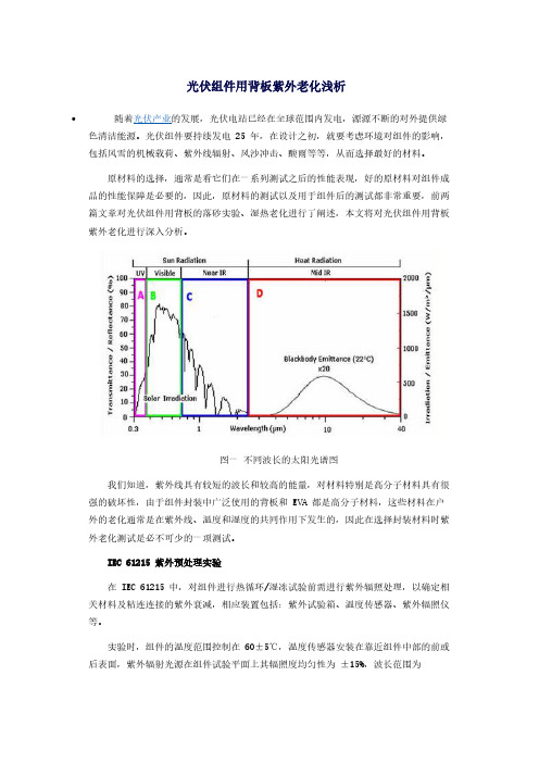
图一不同波长的太阳光谱图 我们知道,紫外线具有较短的波长和较高的能量,对材料特别是高分子材料具有很强的破坏性,由于组件封装中广泛使用的背板和 EVA 都是高分子材料,这些材料在户外的老化通常是在紫外线、温度和湿度的共同作用下发生的,因此在选择封装材料时紫外老化测试是必不可少的一项测试。
IEC 61215 紫外预处理实验 在 IEC 61215 中,对组件进行热循环/湿冻试验前需进行紫外辐照处理,以确定相关材料及粘连连接的紫外衰减,相应装置包括:紫外试验箱、温度传感器、紫外辐照仪等。
实验时,组件的温度范围控制在60±5℃,温度传感器安装在靠近组件中部的前或后表面,紫外辐射光源在组件试验平面上其辐照度均匀性为 ±15%,波长范围为280~320nm 和 320~385nm,精度为 ±15%,其中,组件经受波长在 280~385nm 范围的紫外辐射为 15kWh/m-2,波长在 280~320nm 的紫外辐射为 5kWh/m-2。
要求:紫外辐射后无严重外观缺陷,最大输出功率衰减不超过试验前测试值的5%,绝缘电阻应满足初始试验同样的要求。
回到现实的环境中来 IEC 验证的设计实际上只相当于70天的户外曝晒,而且也没有对组件背面进行曝晒测试,为了更好的理解户外的真实情况,国外一些研究机构,像美国可再生能源实验室NREL、弗劳恩霍夫太阳能研究所 Fraunhofer(ISE)等,建立了各区域的年紫外线剂量,利用这些信息,计算地面至背板的光反射率,模拟出测试条件下的建议曝晒时数,以及沙漠、热带及温带气候下的25年户外曝晒量。
背板环境老化测试分析之系列—黄变篇
背板环境老化测试分析之系列—黄变篇导读:目前常规晶体硅光伏组件采取"钢化玻璃/EVA/电池片/EVA/背板"这种夹心结构封装,背板是组件中直接与外界环境接触的封装材料,其性能的优劣直接影响到整个组件的寿命。
目前常规晶体硅光伏组件采取“钢化玻璃/EVA/电池片/EVA/背板”这种夹心结构封装,背板是组件中直接与外界环境接触的封装材料,其性能的优劣直接影响到整个组件的寿命。
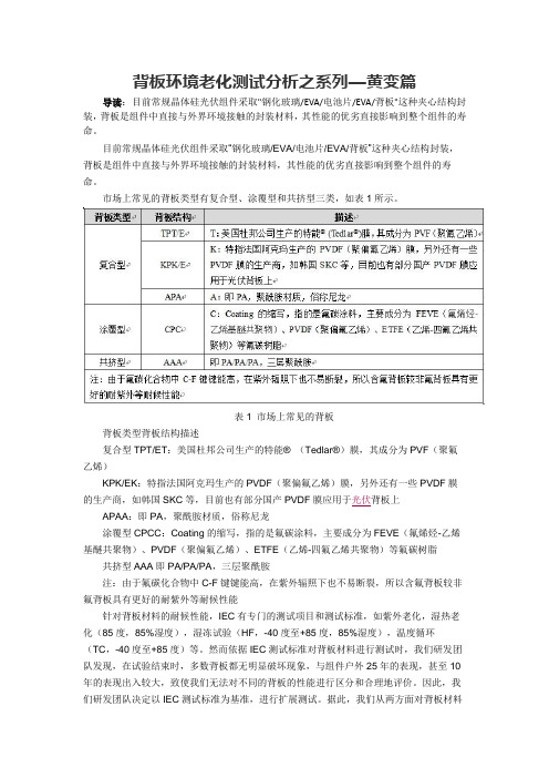
市场上常见的背板类型有复合型、涂覆型和共挤型三类,如表1所示。
表1 市场上常见的背板背板类型背板结构描述复合型TPT/ET:美国杜邦公司生产的特能® (Tedlar®)膜,其成分为PVF(聚氟乙烯)KPK/EK:特指法国阿克玛生产的PVDF(聚偏氟乙烯)膜,另外还有一些PVDF膜的生产商,如韩国SKC等,目前也有部分国产PVDF膜应用于光伏背板上APAA:即PA,聚酰胺材质,俗称尼龙涂覆型CPCC:Coating的缩写,指的是氟碳涂料,主要成分为FEVE(氟烯烃-乙烯基醚共聚物)、PVDF(聚偏氟乙烯)、ETFE(乙烯-四氟乙烯共聚物)等氟碳树脂共挤型AAA即PA/PA/PA,三层聚酰胺注:由于氟碳化合物中C-F键键能高,在紫外辐照下也不易断裂,所以含氟背板较非氟背板具有更好的耐紫外等耐候性能针对背板材料的耐候性能,IEC有专门的测试项目和测试标准,如紫外老化,湿热老化(85度,85%湿度),湿冻试验(HF,-40度至+85度,85%湿度),温度循环(TC,-40度至+85度)等。
然而依据IEC测试标准对背板材料进行测试时,我们研发团队发现,在试验结束时,多数背板都无明显破坏现象,与组件户外25年的表现,甚至10年的表现出入较大,致使我们无法对不同的背板的性能进行区分和合理地评价。
因此,我们研发团队决定以IEC测试标准为基准,进行扩展测试。
据此,我们从两方面对背板材料展开了耐候性测试,【1】在原有IEC测试标准上进行加倍;【2】整合多个IEC测试项目,进行序列老化测试。
光伏板衰减
光伏板衰减
光伏板在使用过程中会出现衰减现象,主要有以下几种原因:
1.光腐蚀:太阳光照射下,光伏板的表面玻璃会产生微小的孔洞,进
而影响光的透射和反射,降低了光电转换效率,使得光伏电池的输出功率
出现了衰减。
2.热衰减:光伏板在使用过程中会出现温度变化,温度升高会导致电
子分布变得不均匀,从而引发光伏板输出功率下降。
3.时间衰减:光伏板使用时间越长,材料老化和损耗就越大,从而引
起光电转换效率的逐渐降低。
为了减少光伏板衰减,可采取以下措施:
1.定期清洗光伏板表面,避免尘埃、污垢等附着物影响光线透射和反射。
2.安装冷却系统,降低光伏板的工作温度,避免热衰减。
3.选择高质量的光伏组件,确保光伏板具有较长的使用寿命和较高的
光电转换效率。
4.在安装光伏板的过程中,选址与面板倾角的设置对于光伏板的输出
功率影响极大,可以考虑通过模拟光照来选定最佳的安装位置和面板倾角。
光伏组件老化测试标准

光伏组件老化测试标准主要有以下几点:
双85老化试验:可以确认组件能否承受高温、高湿之后随之的负温度影响,以及对于温度重复变化时引起的效应,同时考验在高湿度下而产生的热应力及能够抵抗湿气长期浸透的能力。
紫外老化试验:主要模拟自然界的太阳光中的紫外线和环境温度来对产品进行加速耐候性试验,以检验产品长期暴露在户外的耐光老化性能。
热循环试验:主要通过模拟自然界温差变化来对产品进行加速耐候性试验,以检验产品在温度变化条件下的耐光老化性能。
光伏电池背板综述
光伏电池背板综述张传吉;戴建民;成三弟;俞苗锋;谢帆【摘要】论述了光伏电池背板的类型、优缺点和制作工艺以及性能测试方法,概述了近年来国内外光伏电池背板的发展现状,并提出了当前国内光伏背板生产急需解决的问题是要提高自身产品的科技含量、开发具有自主知识产权的产品,提高市场竞争力,实现可持续发展。
%This paper discusses the types, advantages and disadvantages, the production technology, performance test method of photovoltaic ceU backsheet. Applications of photovoltaic cell backsheet were simplely introduced.This article reviewed the experimental and theoretical studies relating to the domestic advance on research of photovohaic cell backsheet.Improve the technological content of products,development of products with own intelligent property rights,enhance market competition ability,realize sustainable development is a problem urgently needed to be solved in Current photovohaic cell backsheet production.【期刊名称】《浙江化工》【年(卷),期】2012(043)002【总页数】4页(P18-20,27)【关键词】太阳能;光伏电池;背板【作者】张传吉;戴建民;成三弟;俞苗锋;谢帆【作者单位】浙江省化工研究院有限公司,浙江杭州310023;浙江省化工研究院有限公司,浙江杭州310023;浙江省化工研究院有限公司,浙江杭州310023;浙江省化工研究院有限公司,浙江杭州310023;浙江省化工研究院有限公司,浙江杭州310023【正文语种】中文【中图分类】TM914.4太阳能光伏电池(简称光伏电池)用于把太阳的光能直接转化为电能,是解决地球污染与能源短缺的有效途径之一。
uv老化条件 光伏
UV老化条件及其在光伏领域的应用1. 介绍随着全球对可再生能源的需求增加,光伏技术作为一种清洁、可持续的能源解决方案受到越来越多的关注。
然而,太阳能电池板在长期使用过程中可能会受到紫外线辐射的影响而产生老化现象。
为了研究和评估光伏组件在实际使用环境下的性能和耐久性,UV老化条件被广泛应用于光伏领域。
2. UV老化条件概述UV老化是指通过模拟太阳光中紫外线成分对材料进行人工老化测试。
这种测试方法可以加速材料老化过程,以便更快地评估材料在实际使用环境中的性能表现。
UV老化条件通常包括以下几个方面: - 光源:通常采用氙灯或者荧光灯作为光源,因为它们能够产生与太阳光相似的紫外线成分。
- 光谱分布:根据不同应用需求,可以选择不同的紫外线波长范围进行测试。
- 辐照强度:辐照强度是指单位面积上的辐射能量,可以根据实际使用环境中的太阳辐射强度进行调整。
- 温度控制:在UV老化条件下,通常需要控制样品的温度,以模拟实际使用环境中的温度变化。
3. UV老化条件在光伏领域的应用3.1 性能评估通过UV老化条件测试,可以评估光伏组件在长期紫外线辐射下的性能表现。
这些性能指标包括: - 光电转换效率:测试前后光电转换效率的变化情况。
- 输出功率衰减:测试前后输出功率的变化情况。
- 绝缘性能:测试前后绝缘材料的电气性能。
3.2 耐久性研究通过UV老化条件测试,可以研究光伏组件在紫外线辐射下的耐久性。
这种研究有助于了解和优化材料、结构和组装工艺对光伏组件寿命和稳定性的影响。
3.3 材料筛选通过对不同材料在UV老化条件下进行比较,可以筛选出更适合光伏组件的材料。
这有助于提高光伏组件的性能和耐久性。
4. UV老化条件的优化为了更准确地模拟实际使用环境,UV老化条件需要进行优化。
以下是一些优化方法: - 光源选择:根据实际使用环境中的紫外线波长分布,选择合适的光源。
- 辐照强度控制:根据实际使用环境中的太阳辐射强度,调整UV老化条件下的辐照强度。
光伏组件用EVA封装胶膜的老化研究进展
PV组件封装用EVA胶膜配方所用各种稳定剂的主要 作用分别为:(1) 通过Cyasorb UV 531 来 TM 吸收紫外线并 猝灭激发态;(2)通过Tinuvin 770 来 TM 终止自由基,(3)通 过Naugard P 分 TM 解氢过氧化物。Pern研究了这些稳定剂 的 有 效 性 , 他 认 为 溶 于 环 己 烷 溶 液 或Elvax 150TM薄 膜 中 的Cyasorb 531TM会迅速发生光分解反应生成未知的芳香 化合物;氢过氧化物分解剂Naugard PTM的加入,只能稍 微减少Cyasorb的光分解;而添加Tinuvin 770TM,可起到 更 有 效 的 稳 定 作 用 ; Tinuvin 770TM和 Naugard PTM对
065
《粘接》杂志社 咨询电话:0710-3626888-8076 传真:0710-3820811 E-mail:zhanjzz@263.net
网址 :w w w.z h a n j i e .c o m .c n
学术论文
ACADEMIC PAPER 综述
Ⅱ型反应,前者产生乙醛并伴随其他一些气体,如CO, CO2,CH4,后者基于脱乙酰的机理上认为醋酸乙烯酯侧 基 从 EVA主 链 的 重 复 单 元 上 脱 落 形 成 乙 酸 和 分 子 主 链 为 聚烯烃的大分子 。 [3] 聚烯烃分子中的共轭双键是生色基 团,它会使EVA分子变色且随着共轭体系的延长,EVA的 颜色还会从浅黄(轻微)到深褐色(严重)逐渐加深[5]。 另外,其他因素也可能加重EVA的变色,如Klemchuk和
聚酰胺光伏背板老化性能及机理研究_蒋超
聚酰胺光伏背板老化性能及机理研究蒋超,彭丽霞,唐景,张增明,傅冬华(阿特斯阳光电力科技有限公司测试中心,江苏常熟215562)摘要:分别研究了在湿热老化、加速湿热老化、紫外辐照老化模式下,背板的力学性能和聚酰胺熔融焓及黄度指数的变化,分析了老化前后背板的断面形貌和表面形貌变化。
结果表明:湿热老化和加速湿热老化聚酰胺趋于结晶以及聚酰胺和玻璃纤维界面作用减弱;紫外辐射老化主要导致酰胺键断开,分子结构破坏。
通过比较老化前后力学性能、黄度指数及表面形貌发现,紫外辐照老化对聚酰胺背板的影响较大。
关键词:聚酰胺光伏背板,玻璃纤维,湿热老化,加速湿热老化,紫外辐照中图分类号:TQ323.6Study on Aging Properties of Polyamide Photovoltaic BacksheetJIANG Chao,PENG Li-xia,TANG Jing,ZHANG Zeng-ming,FU Dong-hua(CSI Photovoltaic Testing Laboratory,Changshu215562,Jiangshu,China)Abstract:The effect of damp heat ageing,accelerated damp heat ageing and UV irradiation ageing on mechani-cal properties、melting enthalpy and yellow index of polyamide photovoltaic backsheet was studied.The fracture and surface characteristic of backsheet was analyzed by scanning electron microscope.The results indicate that polyam-ide go crystallizing and the interaction between glass fiber and polyamide go weaking in precess of damp heat ageing and accelerated damp heat ageing.In precess of UV irradiation ageing,molecular structure of polyamide was de-stroyed.By comparing the mechanical properties、yellow index and surface characteristic,we found that UV irradia-tion ageing gave greater influence to polyamide PV backsheet.Key words:polyamide PV backsheet,glass fiber,damp heat ageing,accelerated damp heat ageing,UV irradia-tion太阳能光伏背板位于组件背面最外层,在户外环境下保护光伏组件不受水汽的侵蚀、阻隔氧气防止氧化,具有良好的耐高低温、绝缘性和耐老化性能,耐腐蚀性能,可以反射阳光、提高组件的转化效率,具有较高的红外反射率,可以降低组件的温度,所以背板性能优劣直接影响着光伏组件能否在户外使用25年。
- 1、下载文档前请自行甄别文档内容的完整性,平台不提供额外的编辑、内容补充、找答案等附加服务。
- 2、"仅部分预览"的文档,不可在线预览部分如存在完整性等问题,可反馈申请退款(可完整预览的文档不适用该条件!)。
- 3、如文档侵犯您的权益,请联系客服反馈,我们会尽快为您处理(人工客服工作时间:9:00-18:30)。
PV BACKSHEET MATERIALS UNDER ACCELERATED AGING CONDITIONS:A PERFORMANCE STUDYSteiner A. J., Krumlacher W., Muckenhuber H., Kraxner M.ISOVOLTAIC AG, Department for Research & DevelopmentIsovoltaicstraße 1, A-8403 Lebring, AustriaPhone: +43 5 9191 9978; Fax: +43 5 9191 79978E-Mail: andreas.steiner@ABSTRACT: Over the last few years, a variety of different PV backsheet materials from various suppliers have emerged in the PV market. Whilst some of these new products rely on well-known and established materials and material combinations, others break new ground by introducing highly engineered new materials and concepts for the use in photovoltaic applications. The aim of the work presented is to compare the performance of different commercially available PV backsheet materials and material combinations regarding their stabilities under various prolonged accelerated aging conditions (e.g.: UV-exposure, damp-heat testing) according to the internationally valid standards (IEC 61730, IEC 61215, UL1703) but exceeding the requirements of those standards by a factor of 2 to 3 with respect to testing times and irradiation energy inputs. Key advantages as well as possible disadvantages of the tested materials are discussed critically, focusing on safety and performance aspects of the backsheet setups under evaluation.Keywords: Qualification and Testing, Reliability, Safety, Durability, PV Backsheet Materials1 INTRODUCTIONDuring its entire lifetime, a photovoltaic module isexposed to various different environmental and electricalstresses. These harmful effects may drastically influencethe module’s electrical performance and lifetime. Beingone of the most outer surfaces of a PV module, thebacksheet has to withstand those environmentalstresses as it has to protect the module’s activecomponents from being degraded or harmed in order toguarantee a long and efficient module lifetime andperformance. Furthermore, the backsheet represents themost vital e lectrical insulation layer on the module’sbackside, therefore being highly relevant by means ofsafety for all glass/backsheet module technologies.High UV exposure, mechanical stresses caused byabrasion or forced deformation, thermal stresses relatedto high temperatures and significant temperature changesas well as hydrolytic material degradation in course oftime just represent some of the most importantenvironmental effects a backsheet has to deal with.Regarding the electrical safety of a PV module, thebacksheet has to guarantee its insulation capacity over themodule’s lifetime in the field.The presented work aims to assay nine differentcommercially available PV backsheet materials andmaterial combinations (see Table I) in terms of vitalsafety, stability and performance criteria in course ofprolonged accelerated aging testing procedures.Table I: Structural Setup of investigated backsheetsMat. No.Structural Setup(outer layer / core layer / inner layer)1 PA / PA /PA2 PA / PET / PA3 PET / PET / Tie Layer4 PVDF / PET / Tie Layer5 PFAVE / PET / Tie Layer6 THV / PET / Tie Layer7 ECTFE / PET / Tie Layer8 PVDF / PET / PVDF9 PVF / PET / PVF 2 DESCRIPTION OF TESTING PROCEDURESThe nine PV backsheet materials under consideration (see Table I) have been tested according to various accelerated aging procedures based on internationally valid standards but exceeding the requirements of those standards by a factor of 2 to 3 with respect to testing times and irradiation energy inputs. The applied testing conditions are briefly mentioned in the following.2.1 ReflectivityReflectivity of the materials under consideration has been measured on the entire backsheet structure in accordance with DIN 5036. Irradiation was done on the inner layer (EVA-side) for a wavelength range of 400 –1000nm and the mean values of spectral reflection in this respective range has been calculated for comparison of the analyzed structures.2.2 UV testingUV testing of the different materials has been done according to ISO 4892-3, using a fluorescent UV lamp with an irradiation maximum of 1.10 W/m² @ 340nm. 1524h of testing according to a 8 hours irradiation / 4 hours bedew-cycle at 60°C yield in a total irradiation energy of 5.03 kWh/m² in the UV B range (280 – 320nm; being in accordance with the requirements of IEC 61215) and 57.8 kWh/m² in the combined UV A + UV B range (nearly 4 times higher than the required 15 kWh/m² according to IEC 61215). The testing has been done on the complete backsheet structures. The respective outer surfaces have been irradiated and changes in yellowing indices (ΔYI) have been calculated according to ASTM 313-05.2.3 Damp heat testingDamp heat testing has been performed on the test specimen at 85°C/85%rh in accordance to IEC 61215 for a total testing time of 2000 hours (twice IEC-standard). The tested backsheet samples have been regularly investigated during this testing time. Optical parameters have been evaluated according to ASTM 313-05 (change in yellowing index, ΔYI). Mechanical parameters (tensilestrength, elongation at break, loss in tensile strength) have been measured according to ISO 527-2 for 10 testing specimen and mean values have been calculated out of these individual testing results.Inner layer adhesion of the materials under consideration (weakest point of adhesion) and EVA adhesion values have been monitored over 2000 hours of damp heat testing foll owing ISOVOLTAIC’s in-house testing procedure (IPV 70; based on 180° peel-testing experiments employing EVA Sanvic Fast Cure).3 RESULTS AND DISCUSSION3.1 Reflectance valuesHigh reflectance values in the range of 400 – 1000nm may positively influence the overall electrical performance of a PV module [1]. The highest values of reflectivity in the wavelength range under consideration have been found for backsheets 1and 8, nearly approaching 90% of mean reflectivity. Whilst all other evaluated materials prove to show reflectivity values between 80 and 90%, backsheet 9(PVF/PET/PVF) shows a rather low reflectivity of only 71% in average (see Table II). These considerably low values can be contributed to the low inherent reflectance of the PVF inner layer of the analyzed backsheet.Table II: Reflectivity of evaluated backsheetsMat. No.Reflectivity [%] (mean value; 400 – 1000nm)1 89 %2 82 %3 79 %4 82 %5 81 %6 81 %7 85 %8 89 %9 71 %3.2 Optical performance in UV and damp heat testingNone of the tested commercially available PV backsheet structures exhibited significant yellowing during 2000 hours of damp heat testing. The measured values for the change in yellowing index (ΔYI) are all found to be below 5 after accelerated aging testing.During UV testing only backsheet 3(PET/PET/Tie layer) showed significant yellowing with a change in yellowing index by more than 10 (see Table III).Table III: Optical performance of analyzed backsheets Mat. No. UV testing DHT testing1 0.9 3.72 0.8 2.03 10.5 3.04 1.6 4.35 0.7 3.46 0.8 0.47 0.8 1.38 0.8 0.49 2.8 2.2This effect might be contributed to insufficient UV-protection of the PET outer layer or of the adjacent adhesive systems, respectively. Similar findings for backsheets using PET as outer surface have been reported earlier by different authors [1, 2].3.3 Mechanical performance during damp heat testingIn course of 2000 hours of damp heat testing, all evaluated PV backsheets showed a decrease in mechanical properties. These changes are considered to be closely related to chemical degradation of the backsheets’ core layers by thermal and hydrolytic attack. The core layers of the materials clearly dominate the backsheets’ overall mechanical performance as they represent the layers of the highest thickness in a PV backsheet. Therefore, electrical safety (insulation) and mechanical stability (tensile strength, elongation at break) is clearly related to the mechanical properties and stabilities of the core layer materials.The evaluated properties for the nine different backsheet setups under consideration are given in Table IV, respectively.Table IV: Mechanical properties of evaluated backsheets Mat.No.tensilestrength(MD)[N/cm]0hDHTtensilestrength(MD)[N/cm]2000hDHTtensilestrength(MD)[% loss]2000hDHTelong.atbreak(MD)[%]0hDHTelong.atbreak(MD)[%]2000hDHT1 125 120 4 220 702 580 480 17 230 1603 320 200 38 190 754 315 255 19 145 805 260 190 27 170 1006 155 105 32 135 557 240 175 27 185 1008 360 break 100 100 break9 490 350 29 200 85All PET-based material setups show a significant drop in their tensile strength after 2000 hours of damp heat testing as a result of thermal and hydrolytic stress on the core layer. Backsheet 8(PVDF/PET/PVDF) even proved to show cracks in the material’s c ore layer after the testing period (see Figure 1). Therefore, testing of the remaining tensile strength and elongation at break was not possible anymore.Figure 1:Cracks in the PET core layer of PVDF/PET/PDVF backsheet 8after 2000 hours DHT.This severe degradation may be contributed to a poor quality of the PET core layer material itself, to insufficient protection of the core layer by the used PVDF outer layers or to a combination of both effects.Backsheet 1(PA/PA/PA) which uses a polyamide based core layer clearly behaves different in terms of tensile strength testing. Whilst initial tensile strength values are found to be very low compared to PET-based backsheets, virtually no decrease in tensile strength is found after 2000 hours of damp heat testing. Therefore, hydrolytic and thermal degradation of the polyamide core layer seems to be lower than degradation of PET based core layers in this respect.In course of damp heat testing also elongation at break is decreasing with all tested backsheets. Apart from the evaluated PVDF/PET/PVDF setup, all tested specimen still showed more than 50% elongation at break after 2000 hours of accelerated aging.3.4 Adhesion during damp heat testingPolyamide based backsheet structures 1and 2 showed the highest and most stable adhesion to the tested EVA after lamination and 2000 hours damp heat testing. All other tested backsheet materials either proved to show considerably low EVA-adhesion even prior to aging or suffered from severe loss in adhesion during damp heat testing (see Table V).Table V: EVA-adhesion of analyzed backsheetsMat. No.EVA adhesionafter Lamination[N/cm]EVA adhesionafter 2000h DHT[N/cm]1 105 802 115 1003 35 324 40 305 70 206 105 207 60 408 50 109 115 40Material combinations using thermoplastic tie layers (backsheets 3 –7) proved to show the lowest adhesion values after 2000 hours of damp heat testing. THV/PET/Tie layer setup 6even exhibited severe delamination on the edges of the tested glass/EVA/EVA/backsheet dummy module setup (see Figure 2).Furthermore, some tie-layer based materials also showed significant loss in their inner layer adhesion after 2000h of damp heat testing, the weakest point of adhesion being the PET/Tie Layer interface (see Table VI).The low EVA-adhesion values of backsheet 8after accelerated aging testing may also be contributed to the poor mechanical properties of the backsheet. After 2000 hours of damp heat testing, breakage of the whole backsheet setup was observed during adhesion testing at approx. 10N/cm. Figure 2: Delamination of THV/PET/Tie layer backsheet 6 after 2000 hours DHT (dummy-module setup).Table VI:Layer adhesion of analyzed backsheets (weakest adhesion of layers)Mat. No.Layer adhesionwithout aging[N/cm]Layer adhesionafter 2000h DHT[N/cm]1 not separable not separable2 8.0 4.03 not separable not separable4 5.0 <1.05 4.5 2.06 not separable not separable7 not separable <1.08 5.0 <1.09 not separable 2.54 CONCLUSIONSIn course of accelerated aging testing, all tested PV backsheet materials have shown signs of degradation due to high temperature, UV-irradiation and hydrolysis effects, respectively. Whilst UV-stability seems to be closely related to the performance characteristics of the outer layers and the adjacent adhesive systems, mechanical properties are largely dominated by the physical properties of the used core layers. High attention has to be paid to the quality of core layer materials and core layer protection by the corresponding outer layers. Thermoplastic tie-layers have shown considerably high initial EVA adhesion for the materials under investigation but generally suffered from a drastic decrease in adhesion values after 2000 hours of damp heat testing.The authors of this paper are well aware of the fact that some of the properties described and evaluated above might be batch and manufacturer-related. Therefore, the authors want to emphasize that the study published in this paper represents the outcome of a testing program with statistical evaluation which has been carried out on commercially available samples of the respective materials. General statements regarding the suitability of various materials or material combinations for their use in PV-module applications based on this study thereforestill remain questionable.5 REFERENCES[1] W. Gambogi, S. Kurian, B. Hamzavytehrany, A.Bradley, J. Trout, O. Fu, Y. Chao, The Role ofBacksheet in Photovoltaic Module Performance and Durability, Proceedings EUPVSEC, Hamburg,Germany (2011).[2] W. Gambogi, Comparative Performance ofBacksheets for Photovoltaic Modules, Proceedings EUPVSEC, Valencia, Spain (2010).。