Hypermesh11.0 HM-3590 Morph Adhesive Layers
hypermesh11.0柔性体文件计算
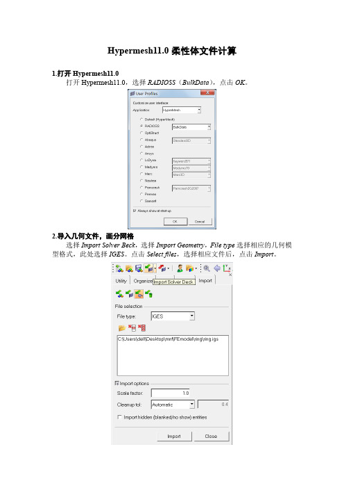
Hypermesh11.0柔性体文件计算1.打开Hypermesh11.0打开Hypermesh11.0,选择RADIOSS(BulkData),点击OK。
2.导入几何文件,画分网格选择Import Solver Beck,选择Import Geometry,File type选择相应的几何模型格式,此处选择IGES。
点击Select files,选择相应文件后,点击Import。
3.网格划分网格划分部分省略。
注意删除2D网格,可仅保留3D网格。
4.设置材料属性点击Materials(create)。
Mat name中填写材料名称,选择颜色,Type选择ALL,card image选择MAT1(均质)。
点击create/edit。
进入create/edit编辑页面,设置其中的E(弹性模量),NU(泊松比)和RHO (密度)。
例如steel(钢)材料如下设置,需要注意默认单位为Kg、mm和N。
点击return。
5.设置特性卡片点击Properties(create),prop name中输入特性卡片名称,选择颜色,type 选择3D,card image选择PSOLID,material选择步骤4中设置的材料(steel),点击create。
6.赋予网格材料属性点击Properties(assign),选择element,type选择3D,property选择步骤5中设置的特性卡片。
在屏幕中框选所有3D网格,然后点击assign。
查看左下角说明,确保材料正确赋予网格。
点击return。
7.创建载荷卡片点击Load Collectors(create),loadcol name填写CMS,选择颜色,card image 选择CMSMESH,点击create/edit。
进入CMS卡片编辑界面,其中METHOD选择CB(约束模态),NMODES 填写所需值。
模态阶数计算方法为:6+NMODES*节点数。
HyperMesh入门教程
HyperMesh入门教程HyperMesh的界面介绍HyperMesh的几何建模和清理HyperMesh的网格剖分和优化HyperMesh的连接建立和检查HyperMesh的材料和属性定义HyperMesh的载荷和约束设置HyperMesh的模型导出和导入HyperMesh的界面介绍菜单栏:位于界面顶部,包含了各种功能菜单,如File、View、G eometry、Mesh等。
工具栏:位于菜单栏下方,包含了常用的工具按钮,如Select、M ove、Rotate等。
面板区:位于界面左侧,包含了各种功能面板,如Model Browser、Entity Editor、Connectors等。
图形区:位于界面中央,用于显示和操作模型。
状态栏:位于界面底部,用于显示当前的操作模式、坐标系、鼠标位置等信息。
HyperMesh的几何建模和清理HyperMesh可以通过两种方式创建几何模型:从零开始创建:使用Geometry菜单中的各种工具,如Point、Line、Surface等,可以创建基本的几何实体,并通过Boolean运算等方式进行组合和修改。
无论是哪种方式创建的几何模型,都需要进行一定的清理工作,以保证模型的质量和完整性。
HyperMesh提供了一系列的几何清理工具,如Geometry菜单中的Check、Edit、Cleanup等选项。
常见的几何清理操作包括:检查并修复几何实体之间的重叠、交叉、间隙等问题。
检查并修复几何实体内部的自相交、重复点线面等问题。
检查并修复几何实体之间的拓扑关系,如共享点线面等。
检查并修复几何实体的法向方向,确保法向一致性。
检查并修复几何实体的尺寸和形状,避免过大或者过小、过扁或者过尖等问题。
HyperMesh的网格剖分和优化网格剖分是将连续的几何实体离散为有限个节点和单元,以便进行有限元分析。
HyperMesh支持多种类型的网格剖分方法,如:2D网格剖分:将平面或者曲面实体剖分为三角形或者四边形单元。
hypermesh基础培训教程(多场合)
hypermesh基础培训教程(多场合)Hypermesh基础培训教程一、引言Hypermesh是一款功能强大的有限元前处理器,广泛应用于结构分析、热分析、流体分析等领域。
本教程旨在帮助初学者快速掌握Hypermesh的基础操作,为后续的高级应用打下坚实基础。
通过本教程的学习,读者将能够熟练地进行几何建模、网格划分、材料属性定义、边界条件施加等基本操作。
二、Hypermesh界面及基本操作1.启动Hypermesh在安装完Hypermesh软件后,双击桌面图标启动程序。
初次启动时,系统会提示设置工作目录,选择一个便于管理的路径即可。
2.界面介绍Hypermesh界面主要包括菜单栏、工具栏、主窗口、状态栏等部分。
菜单栏包含文件、编辑、视图、网格、工具等菜单,通过菜单可以执行各种操作。
工具栏提供了常用的快捷操作按钮,方便用户快速执行命令。
主窗口用于显示几何模型、网格、分析结果等。
状态栏位于界面底部,显示当前操作的状态信息。
3.基本操作(1)打开模型:通过菜单栏“文件”→“打开”命令,选择相应的几何文件(如iges、stp等格式),打开模型。
(2)缩放、旋转、平移视图:通过工具栏的相应按钮,可以调整视图的显示。
同时,鼠标滚轮可以控制视图的缩放。
(3)选择元素:鼠标左键单击选择单个元素,按住Ctrl键同时单击可以选择多个元素。
(4)创建集合:通过菜单栏“编辑”→“创建集合”命令,可以将选中的元素创建为一个集合,便于后续操作。
(5)撤销与重做:通过菜单栏“编辑”→“撤销”或“重做”命令,可以撤销或重做上一步操作。
三、几何建模1.几何清理在实际工程中,导入的几何模型往往存在冗余面、重叠边等问题,需要进行几何清理。
Hypermesh提供了丰富的几何清理工具,如合并顶点、删除线、删除面等。
2.创建几何元素Hypermesh支持创建点、线、面、体等几何元素。
通过菜单栏“几何”→“创建”命令,选择相应的几何元素创建工具,如创建点、创建线、创建面等。
hypermesh教程2.doc
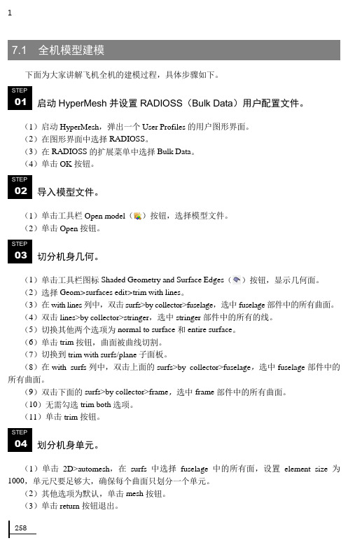
12587.1 全机模型建模下面为大家讲解飞机全机的建模过程,具体步骤如下。
启动HyperMesh 并设置RADIOSS (Bulk Data )用户配置文件。
(1)启动HyperMesh ,弹出一个User Profiles 的用户图形界面。
(2)在图形界面中选择RADIOSS 。
(3)在RADIOSS 的扩展菜单中选择Bulk Data 。
(4)单击OK 按钮。
导入模型文件。
(1)单击工具栏Open model ()按钮,选择模型文件。
(2)单击Open 按钮。
切分机身几何。
(1)单击工具栏图标Shaded Geometry and Surface Edges ()按钮,显示几何面。
(2)选择Geom >surfaces edit >trim with lines 。
(3)在with lines 列中,双击surfs>by collector>fuselage ,选中fuselage 部件中的所有曲面。
(4)双击lines>by collector>stringer ,选中stringer 部件中的所有的线。
(5)切换其他两个选项为normal to surface 和entire surface 。
(6)单击trim 按钮,曲面被曲线切割。
(7)切换到trim with surfs/plane 子面板。
(8)在with surfs 列中,双击上面的surfs>by collector>fuselage ,选中fuselage 部件中的所有曲面。
(9)双击下面的surfs>by collector>frame ,选中frame 部件中的所有曲面。
(10)无需勾选trim both 选项。
(11)单击trim 按钮。
划分机身单元。
(1)单击2D>automesh ,在surfs 中选择fuselage 中的所有面,设置element size 为1000,单元尺要足够大,确保每个曲面只划分一个单元。
Hyperworks 11.0培训word版本2 Morphing
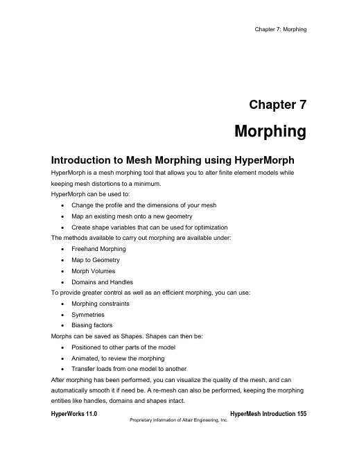
Chapter 7MorphingIntroduction to Mesh Morphing using HyperMorph HyperMorph is a mesh morphing tool that allows you to alter finite element models while keeping mesh distortions to a minimum.HyperMorph can be used to:∙Change the profile and the dimensions of your mesh∙Map an existing mesh onto a new geometry∙Create shape variables that can be used for optimizationThe methods available to carry out morphing are available under:∙Freehand Morphing∙Map to Geometry∙Morph Volumes∙Domains and HandlesTo provide greater control as well as an efficient morphing, you can use:∙Morphing constraints∙Symmetries∙Biasing factorsMorphs can be saved as Shapes. Shapes can then be:∙Positioned to other parts of the model∙Animated, to review the morphing∙Transfer loads from one model to anotherAfter morphing has been performed, you can visualize the quality of the mesh, and can automatically smooth it if need be. A re-mesh can also be performed, keeping the morphing entities like handles, domains and shapes intact.Accessing HyperMorphHyperMorph can be accessed in one of the following ways:∙From the menu bar, point to Morphing, and select the appropriate function:Figure 1: HyperMorph on the menu bar∙On the Tool page click on HyperMorph, and click on the appropriate panelFigure 2: HyperMorph on the Tool pageHyperMorph Online HelpThe on-line help for HyperMorph can be accessed as follows:1. On the Help menu, click HyperMesh, OptiStruct, and Batch Mesher.2. All files referenced in the HyperMorph tutorials are located in the HyperWorksinstallation directory under<install_directory>/tutorials/hm/hypermorph.Section 1: Morph VolumesA morph volume is a six-sided hexahedron whose shape can be manipulated to morph the mesh. The length and curvature of each edge of a morph volume can be modified independently. Adjacent morph volumes can be linked through tangency conditions. This allows you to update the characteristics of the morph volumes. Handles are placed at each of the vertices of the morph volumes. Morphing involves moving these handles. Morph volumes thus present a very simple, powerful, and intuitive way to morph.Morph volumes will only influence the nodes that are registered to it. You can either, register the nodes within a morph volume automatically when it is created, or you can select the nodes or nodes on selected elements to be registered. If the morph volumes do not appear to be morphing nodes inside them, you may need to register those nodes.Figure 1: Morph VolumesSection 2: Domains and HandlesThe domains and handles approach consists of dividing the mesh into regions called domains with associated handles.What are domains and handles?Domains consist of selected nodes and elements.Domains and handles are divided into two basic groups, global and local.The global group consists of global domains, each of which is associated with a number of global handles. Global handles will only influence the nodes in the global domain to which they are associated. Global handles and domains are best for making large scale shape changes to the model.The local group consists of five types of local domains: 1D domains, 2D domains, 3D domains, edge domains, and general domains. Local handles/edge domains can only influence nodes contained in the domains they are associated with. Local handles/edge domains are intended to be used to make small scale, parametric changes to the model. While a model can contain both global and local handles and domains, it is not necessary to have both types of domains and handles in a model.The following table describes the various domains and their symbols when they are createdWhen global domain and handles are generated using autogenerate or created with the create handles option turned on, HyperMorph generates eight global handles, one at each of the eight corners of a box laid out along the global axes surrounding the model. These global handles are named “corner” followed by a number from one to eight. HyperMorph willalso place at least one global handle w ithin the box in areas of the model’s peak nodal density. The se handles are named “handle,” f ollowed by a number.The automatic global handle generation works particularly well for space-frame models such as full car models. However, for small models such as a control arm or bracket, the recommendation is for you to build your own local domains and handles since you are more likely interested in changing the local area rather than the entire model.If the autogenerate process does not create handles in the positions where you want them to be, you can always delete them, reposition them, or create additional handles. Handles can be further classified as independent or dependent. An independent handle creates displacements to the model only when it is moved. A dependent handle creates displacements influenced from its own movements plus that of other handles it is linked to.A handle can be made dependent on one or more handles. This allows you to create as many layers of dependencies between your handles as you desire. For example, you can make all the handles at one cross section of a beam (modeling using 2D shell elements) dependent on a single handle allowing you to move an entire cross section while only having to select one independent handle.What is a partition?The most important factor in local morphing is partitioning. It is logically dividing a 2D domain into smaller 2D domains, such as where the angle between elements exceeds a certain value or where the domain changes from flat to curved, is called partitioning. Proper partitioning makes morphing faster and easier. By activating partition domains user can invoke partitioning when auto-generating or when creating a domain. If the user is unsatisfied with the results of the partitioning he/she can change the partitioning parameters namely domains angle and curve tolerance.Figure below shows an example of partitioning. For the model on the left, the 2D domain was created without partitioning. For the model on the right, partitioning was used. Note how the 2D domains divide along angle and curvature change boundaries.Figure 2: Partitioning domainsSection 3: Map to GeometryMap to Geometry provides quick ways of taking an existing mesh and conform it to a new geometry. Domains and handles can be used to provide better control on the morphing process. The geometry can be a line, node list, plane, surfaces, or elements using edge domains and handles to guide the process. Geometry can also be provided in the form of section lines, or surfaces.Some of the types of geometry that can be mapped are shown in figure 1.Figure 1: Types of geometry that can be mappedExercise 7a: Map To GeometryIn this exercise, you will use the line difference approach to morph a bumper toconform to a new section line.Figure 1: Bumper before and after morphingStep 1: Load and review the model.1. Open the HyperMesh file, Exercise_7a.hm.Step 2: Morph the bumper.1. Access the map to geom panel through the menu bar by selecting Morphing > Map toGeometry.2. Change the geometry selector to line difference.3. Select the from line and the to line as shown in figure 2.4. Toggle the morphing entity (2nd column) from map domains to map nodes.5. Select nodes >> displayed.6. Verify that no fixed nodes is selected under map nodes.7. Use map by line axis morphing with a 1.0mvbias and fxbias.Figure 2: The from line and the to line8. Click map.SummaryThe profile of the bumper is changed to follow the new section line.Exercise 7b: Using Domains and HandlesIn this exercise you will create domains and handles, and morph the model.Step 1: Load and review the model.Open and review the HyperMesh model morphing_7b.hm.Step 2: Auto generate 2-D domains and handles.1. Access the Domains panel,create subpanel through the menu bar by selecting Morphing >Create > Domains.2. Change the create method to auto functions.3. Click generate.Based on the model’s geometric features, all of the model’s elements are organized into various domains and local handles are created and associated with the domains.Step 3: Move elements into a new 2-D domain.1. Verify you are still in the Domains panel, create sub-panel.2. Set the selector to 2D domains.3. Use the toggle to switch from all elements to elems.3. Click to clear the elements that were automatically selected.4. Using elems >> by window, select the elements indicated in figure 1.Figure 1: Elements to select to move into a new domain5. Verify that partition 2D domains is active.6. Click create to create the domain.Local handles are created for the new domain. You should now have two local domains.Elements can only belong to one domain at a time. Thus, the elements you selected were moved into the new domain. This functionality makes it very easy to group elements into differentdomains.Step 4: Split the edge domain of the radius to have more control when morphing.1. While in the Domains panel, select the edit edges subpanel.2. Verify that the split option is selected.3. With the domain se lector active, select the edge domain of the part’s radius as indicated in theFigure 2.The node selector automatically becomes active once the edge domain is selected. Click the domain selector to make it active and see that you selected the desired edge domain.Figure 2: E dge domain to select4. Click the node selector to make it active.5. Select the node on the positive Y-axis end of the radius, as indicated in the image Figure 3.Figure 3: Node selection to split the edge domain of the radius6. Click split to split the edge domain at the node.7. Repeat the above process to further split the edge domain of the radius, this time at the nodeindicated in the Figure 4.Figure 4: Node selection to further split the edge domain of the radius8. When complete, click return to exit the panel.Step 5: Add local handles to the 2-D domain on the part’s left side.1. Go to the Handles panel,create subpanel through the menu bar by selecting Morphing >Create > Handles.2. For name =, enter local.3. Click the attached to: domain selector to make it active.4. Select the 2-D domain on the part’s left side by selecting its red icon, as indicated in the followingimage.Figure 5: Adding handles to a 2-D domain5. Click the by nodes: nodes selector to make it active.6. Select the two nodes as indicated in the previous image.7. Click create to create the handles and add them to the 2-D domain.8. Click return to exit the panel.Step 6: Perform basic morphing to understand how domains and handles interact with each other and the mesh.1. Go to Morph panel move handles subpanel through the menu bar by selecting Morphing >Morph and then select move handles.2. With the handles selector active, select the two handles that are on the most positive X-axis endof the part, as indicated in figure 6.If you select one or more handle, those handles follow the handle you drag (in Step 6.6, following).3. Switch from on domains to on plane.4. Click the N1 selector to make it active.5. For N1N2N3, select any three nodes on the model to define a plane.6. Click morph.7. The message, “pick handles and move to new location” appears in the message bar.8. Click on and drag one of the selected handles to morph the part.9. As you drag the handle, the mesh’s size and shape is adjusted.Notice that the following occurs as the selected local handle is moved:∙ The handles selected in Step 6.2 follow the handle you are dragging.∙ All of the elements belonging to the selected local handle’s 2-D domain are affected by moving that local handle.∙ The 2-D domain’s non-selected local handles act like anchors (they do not move).∙ The nodes on the edge domains and between any two non-selected local domains do not move.∙ None of the elements in the other 2-D domain are affected.10. Release the mouse button to complete the morphing operation.Figure 6: E xample result of morphing the model11. Click undo.The HyperMorph module allows for multiple levels of undo and redo for all morphing operations.This functionality is available for any particular HyperMesh session and its current model as long as the session and its model remain open.12. Click to clear the selected handles.13. (Optional) With the handles selector active, select one or more global handles14. Click morph.15. Click on and drag any global handle to morph the part.SummaryThe following occurs as the selected global handle is moved:∙ The handles selected in Step 6.2 follow the handle you are dragging.∙ The non-selected global handles act like anchors (they do not move).∙ All of the elements, local handles and edge domains are affected.Eercise 7c: of Morph VolumesThis exercise shows how to smoothly change the shape of a B-pillar via morph volumes.Figure 1: B-P illar before and after morphingStep 1: Load and review the model.Open the HyperMesh file, Exercise_7cStep 2: Create morph volumes.1. Access the Morph Volumes panel Create subpanel through the menu bar by selectingMorphing > Create > Morph Volumes.2. Switch the creation method to pick on screen.3. For handle placement, select corners only.4. Keep the auto-tangent check box selected.5. Draw a window by clicking at the four places shown in Figure 2.Figure 2: P oints for creating the morph volumeNote: A morph volume is created, enclosing the area.Step 3: Split the morph volumes.1. Select the split/combine subpanel.2. Verify the split toggle is set to split mvols : by edge s3. Select an edge of the morph volume close to location 1(Figure 3).Figure 3: Locations to split the morph volumeThe green colored cross moves to the location of the black dot.4. Click split.The morph volume is split into two.5. Follow the same steps to create another split at location 2.Step 4: Change the profile of the b-pillar.1. Access the Morph panel,move handles subpanel through the menu bar by selectingMorphing > Morph and then select move handles.2. Set the morphing method to translate.3. For direction use along xyz.4. Key in the following values:X =0Y =100.00Z =05. Select the eight handles by window as shown in Figure 4.Figure 4: Select handles for morphing6. Click morph.Rotate the model to observe that the b-pillar is morphed.SummaryThe b-pillar is morphed in a smooth fashion with minimum distortion to the elements.。
hypermesh帮助文档(中文)
Altair软件Hyperworks10.0Hypermesh功能操作中文版张燕华译一字一句打上,不妥之处难免,还望大家批评指正中文资料optistruct指南文档(付费)碰撞关键字(控制文件)中文版(免费)Hypermesh与abaqus接口文档(免费) Hypermesh与dyna接口文档(免费)Hypermesh指南文档(免费)ANSA(网格划分部分)(免费)疲劳Ncode7.0(design life) (免费)更多软件和法规,范例资料,慢慢翻译积累资料声明资料翻译费时费力,希望能让您的学习过程感到省时,给力!我本来不想发行电子版的,传到网上可能会被复制,粘贴,so easy的事情,我就得 “被雷锋”了。
个人建议:或许您能够偶尔得到一份只言片语的资料,或者是某个方面的资料,但是如果您想得到更多更全的学习资料,建议你亲自联系我们。
比如,做碰撞的,想学习NVH,学习流体,学习疲劳,电磁场等;做汽车行业的,想看看其他行业(如航空,重工,电子产品,生命科学)主打软件是什么,比如高薪的航空工业疲劳分析工程师,一汽,泛亚,上海大众,上汽,北汽疲劳工程师主要应用Ncode(疲劳软件的鼻祖,功能最全,最强大);还有船舶行业patran软件,很多经典资料(像Patran PCL Workshop Notes)还木有中文版。
在一个或两个方面特别精通的基础上,再对其它方面熟悉,或许您会更受业内欢迎。
如果您需要更多,关于Hyperworks,ansa,MSC.patran,nastran,dytran;LS-dyna,abaqus,adams,ansys,madymo,MoldFlow,MARC, Ncode,Optistruct帮助文档中文版。
请联系:QQ:290538306邮箱:zzuzhangyanhua@很多资料国内代理公司不公开或者根本没有。
到我们这里,某些已有中文版,暂时没有的资料可以从无到有,欢迎团购,更欢迎个人。
Hypermesh11.0HM-3550MorphVolume
Hypermesh11.0HM-3550MorphVolume预览说明:预览图片所展示的格式为文档的源格式展示,下载源文件没有水印,内容可编辑和复制HM-3550: Morph VolumeExercise: Changing the Shape of the B-pillar with the Help of Morph VolumeThis exercise shows how to smoothly change the shape of a B-pillar via morph volumes.Figure 1: B-Pillar before and after morphingStep 1: Load and review the model.Open the HyperMesh file, body_side.hm.Step 2: Create morph volumes.1. Click the Morphing menu in the menu bar and pick Create > Morph Volumes2. Switch the creation method to pick on screen.3. For handle placement, select corners only.4. Keep the auto-tangent check box selected.5. Draw a window by clicking at the four places shown in Figure 2.Figure 2: Points for creating the morph volumeNote: A morph volume is created, enclosing the area.Step 3: Split the morph volumes.1. Click the split/combine subpanel in the Morphing panel.2. Verify the split toggle is set to split mvols : by edges3. Select an edge of the morph volume close to location 1(Figure 3).Figure 3: Locations to split the morph volumeThe green colored cross moves to the location of the black dot.4. Click split.The morph volume is split into two. Follow the same steps to create another split at location2.Step 4: Change the profile of the b-pillar.1. Click the Morphing menu and pick Morph. Click the move handles subpanel if not already open.2. Set the morphing method to translate.3. For direction use along xyz.4. Key in the following values:x val =0y val =100.00z val =05. Select the eight handles by window as shown in Figure 4.Figure 4: Select handles for morphing6. Click morph.Rotate the model to observe that the b-pillar is morphed.SummaryThe b-pillar is morphed in a smooth fashion with minimum distortion to the elements.。
hypermesh常用面板及快捷键之令狐采学创编之欧阳家百创编
hypermesh 面板欧阳家百(2021.03.07)HyperMesh的主要面板1、几何面板Nodes(节点)子面板的选项及功能Lines(线)子面板的选项及功能Surfaces(曲面)子面板的选项及功能1、单元面板Onedimensional(一维单元)子面板的选项及功能shells(壳单元)子面板的选项及功能Solids子面板的选项及功能2、载荷和边界条件面板载荷和边界条件面板3、管理面板管理面板4、结果面板结果面板6、编辑面板编辑面板7、输入/输出面板输入/输出面板8、客户化面板客户化面板9、视图面板视图面板10、xy绘图面板Xy绘图面板11、混合面板混合面板12、优化面板优化面板13、安全性分析安全性分析面板14、求解器面板求解器面板Hypermesh中常用快捷键Hypermesh中常用快捷键F1 Hidden Line 隐藏线F2 Delete 删除(删除任何对象都用此命令)F3 Replace 合并两个节点F4 Distance 测量距离,角度等F5 Mask 隐藏F6 Element Edit 单元编辑(创建,合并,分割单元等)F7 Align Node 节点共线排列F8 Create Node 创建节点F9 Line Edit 线编辑(非边界编辑)F10 Check Elem 单元质量检查F11 collectorsF12 Automesh 自动网格划分Shift+F1F12 Ctrl+F1F6Key Function key only plus SHIFT plus CTRL keyF1 hidden line color print slideF2 delete temp nodes slide fileF3 replace edges print eps (Note: Works only on UNIX)F4 distance translate eps fileF5 mask find print b/w eps F6 element edit split JPEG file F7 align node projectF8 create node node editF9 line edit surf editF10 check element normalsF11 collectors organizeF12 automesh smootha arc 弧形b back返回以前视图c centerd display 进入显示面板f fill 以适当比例全图形窗口显示模型g global 进入Global参数设置面板h 打开在线帮助文件m 显示/关闭下面的工具面板o option 显示选项参数设置面板p plot 刷新显示r rotates slide 移动缩放,鼠标上下拖动时缩放t true view 设定视角显示v 进入user view dialogw windowsz zoom,按住鼠标在模型上画一个圈,松开鼠标后即显示圈内部分Hypermesh中常用英文关键词dangle 摇摆Warpage 翘曲, 扭曲, 热变形Aspect_Ratio 纵横比屏幕高宽比Split v.劈开, (使)裂开, 分裂, 分离 n.裂开, 裂口, 裂痕Tria Triaangle trigon n.三角形,ellipsoid n.椭圆体project 投影计划实施normals 法线align node 对齐节点surfaces and faces 曲面和表面duplicate adj.复制的 n.复制品 vt.复写, 复制reject 否定拒绝exponential 指数tol tolerance 公差mandatory 命令的, 强制的, 托管的retrieve v.重新得到 n.找回centroid n. 质心trim adj. 整齐的, 整洁的 vt. 整理, 修整, 装饰morph 变形Solid 体Connectors 焊点Loads (constraints, forces, pressures,etc.) 约束,集中力,面力等Equations (mathematical link between nodes) 约束方程Multibodies 多刚体equivalency n. 相等, 等价skew adj. 歪斜的abort 异常中断, 中途失败biasing 偏置, 偏压algorithm [数]运算法则curvature 弯曲, 曲率chordal 弦的似弦的Interior Angle 内角Aspect Ratio 长宽比Skew Angle 扭曲程度Warp Angle 翘曲度Chordal Deviation 弦差Jacobian 雅可比plate 面solid 体hexa hexahedral 六面体的TetraMesh 四面体网格划分detach 分开分离criteria 标准Drag 拉伸Spin 旋转Line Drag 沿线拉伸Element Offset 单元偏移Linear Solid 线性近似Solid Map 映射beamsectcols 保存梁截面信息的collectorbeamsects 梁截面nonrigid adj.非刚性的Moments of inertia 转动惯量arrow tip 箭头invoke 调用intersect vt. 横断 vi. (直线)相交, 交叉conics n.圆锥曲线论, 锥线论NURBS (nonuniform rational Bspline) Used to represent lines that are not straight or elliptical.piecewise adv.[数]分段地planar 平面的tangent 切线permute 序列改变 The permute panel allows you to permute node,element, point, line, surface, and component data. Use this function to exchange the axes of a coordinate system.reparam (reparameterize) 确定参数torus Used to represent a toroidal surface. 超环面cone 锥形物圆锥体nested 嵌套的pertaining to 属于关于附属menu buttongreen Functions or executable itemsyellow Collectorsred Return or abort (异常中断)cursor n. 指针rectangular adj. 矩形的, 成直角的tetrahedral adj. 有四面的, 四面体的specular adj. 镜子的weld vt.焊接 n.焊接, 焊缝thetaadjacent 邻近的, 接近的utility 效用有用pinhole n.针孔, 小孔filletbead 筋冲压beam 梁edge fillet 边缘倒圆过渡圆滑部分planar adj. 平面的, 平坦的contour 云图如果一个面和超过一个面以上共同使用一条边界,就认为是连续的(“HyperMe sh里称为:equivalenced”)toggle 一次合并一条边界(手工)–鼠标左键点击自由边可以变成共享边,点击共享边可以变成压缩边–鼠标右键点击共享边可以变成自由边,点击压缩边可以变成共享边equivalence 一次可以合并很多边界(自动)–按给定的条件查找曲面上的一对自由边界,并合成成共享边;toggle 一次合并一条边界(手工)–鼠标左键点击自由边可以变成共享边,点击共享边可以变成压缩边–鼠标右键点击共享边可以变成自由边,点击压缩边可以变成共享边Replace 一条边替代另一条(也是合并成一条)–合并两条带有一定间隙的自由边成一条共享边;–可以控制哪条边界保留,哪条边界移动;defeature: 面板duplicates: 重复面–查找并删除重复面quick edit : 面板filler surf:填补曲面–在自由曲面边界上,选择一条线来自动修补丢失的面。
Hypermesh分析设定ppt课件
力加载 forces
扭矩加载 moment
重力
创建接触属性及接触如下图所示
边界条件
gap
求解设置
设置分析步,包括分析所包含的特定的边界条件及分析类型。
Control card界面
提交运算
至此,可以将搭建好的模型提交给求解器求解。提交运算有两种方法: 1. 通过导出相应的求解器输入文件进行提交;
hypermesh直接支持多种主流求解器格式结构分析应力nvh疲劳非线性结构分析radiosslinearabaqusnastranansysmarcnsoft制造分析流动分析moldfilling挤压分moldflowcmoldhyperextrude安全性分析冲击碰撞乘员安全性分析dynapamcrashradiossmadymo优化分析拓扑形貌形状尺寸参数optistructnastran材料创建或编辑材料材料名称材料类型过滤材料类型材料名称
材料
材料名称:要创建或编辑的材料名称
材料类型过滤:快速选择材料类型
材料类型:所定义的材料类型,分别为:mat1、mat2、mat4、mat5、mat8、mat9和 mat10。 Mat1:为线性弹性材料。
创建或编 辑材料
材料名称
材料类型过滤
材料类型
材料属性
属性名称:要创建或编辑的材料名称 属性类型过滤:快速选择属性类型 属性类型:所定义的材料属性类型,常用的有pbar、pbeam、pshell、psolid 所用材料:属性所用的材料名称
Hypermesh教程
分析设定
分析设定
分析设定是指除网格之外的所有分析数据,包括:
• 创建材料、属性等. • 创建边界条件(约束、载荷、接触等) • 定义其它需要的信息(求解要求,运行参数等)
HyperMesh入门教程[3]
HyperMesh入门教程HyperMesh的安装和启动HyperMesh的界面和工具栏HyperMesh的文件管理和导入导出HyperMesh的几何建模和编辑HyperMesh的网格划分和质量检查HyperMesh的材料和截面定义HyperMesh的单元和集合管理HyperMesh的加载和约束设置HyperMesh的输出控制和求解器选择HyperMesh的后处理和结果分析HyperMesh的安装和启动要安装HyperMesh,您需要先HyperWorks套件的安装程序,然后按照提示进行安装。
安装过程中,您需要输入您的许可证信息,选择您需要的组件(包括HyperMesh),以及指定安装路径。
安装完成后,您可以在开始菜单或桌面上找到HyperMesh的图标,双击即可启动软件。
启动HyperMesh后,您会看到一个欢迎界面,上面有几个选项,如下图所示:![HyperMesh欢迎界面]New:创建一个新的HyperMesh项目,需要指定项目名称、工作目录、单位系统和求解器类型。
Open:打开一个已有的HyperMesh项目,需要选择项目文件(扩展名为.hm)。
Import: 导入一个外部文件,可以是几何文件(如.iges, .step, .stl等),网格文件(如.nas, .inp,.cdb等),或结果文件(如.op2, .odb, .h3d等)。
Recent:显示最近打开或创建的HyperMesh项目列表,可以直接其中一个进行打开。
Exit: 退出HyperMesh软件。
HyperMesh的界面和工具栏当您创建或打开一个HyperMesh项目后,您会进入主界面,如下图所示:![HyperMesh主界面]标题栏:显示当前项目的名称、单位系统和求解器类型。
菜单栏:提供各种菜单选项,如File, Edit, View,Tools等,可以进行文件管理、视图控制、工具设置等操作。
工具栏:提供各种快捷按钮,如New, Open, Save, Undo,Redo等,可以进行常用操作。
- 1、下载文档前请自行甄别文档内容的完整性,平台不提供额外的编辑、内容补充、找答案等附加服务。
- 2、"仅部分预览"的文档,不可在线预览部分如存在完整性等问题,可反馈申请退款(可完整预览的文档不适用该条件!)。
- 3、如文档侵犯您的权益,请联系客服反馈,我们会尽快为您处理(人工客服工作时间:9:00-18:30)。
HM-3590: Morph Adhesive Layers
Objective
Use morphing to change the thickness of the middle layers of a four-layered solid, while maintaining the thickness of the outer layers.
Tools
Domains will be created using 3D domains > by component. Thickness will be altered using alter dimensions.
Step 1: Open the file.
1. Open the file, Morph_Adhesive_Layers.hm.
Step 2: Create domains and handles.
1. Click the Morphing menu and pick Create >Domains.
2. Switch the domain type to 3D domains.
3. Toggle the element selector to all elements.
4. Activate the divide by comps and partition 2D domains options. The panel should appear as in the following image:
5. Click create to create the domains.
6. Click return to exit the Domains panel.
Step 3: Display only the morph faces of interest.
1. Using the Model Browser, hide all the components except ^morphface.
2. Mask all ^morphface elements except those on the outer layer and the layer between the Outer comp and the Adhesive_Outer to leave all the elements shown in the following
image.
HINT: Select a couple of elements on the face you want to keep. Select elements >> by face, and then select elements >> reverse. This will reverse the selection to the elements you do not want and will allow you to mask those elements with the mask button.
3. To reduce the number of domains and handles shown on the screen, click the Mask tab.
4. Click the + next to Morphing to expand it.
5. Click the + in the Show column for Local Domains/Handles to display the domains and handles for only the displayed elements.
6. Hide the ^morphface component in the Model Browser.
Step 4: Increase the thickness of the outer adhesive layer by 5 units.
1. Click the Morphing menu and pick Morph to open the Morph panel.
2. Open the alter dimensions subpanel.
3. Change the dimension type to radius.
4. Activate the add to current checkbox.
5. For domains, select the curved edge domains as well as the 2-D domains representing the curved surfaces as seen in the following image.
6. Set the center calculation to by axis.
7. For the axis, use the z-axis.
8. For B select the temp node that represents the center of the cylinder.
9. In radius= box, change value to 5 units.
10. Click morph.
11. Go to the save shape subpanel.
12. For name= enter sh1.
13. Switch to as node perturbations.
14. Click save.
15. Click undo all to revert back to the original model configuration.
16. Show all components except the ^morphface component.
17. Go to the apply shapes subpanel.
18. For shapes select sh1.
19. Click select.
20. Click animate.
This takes you to the Deformed Shape panel.
21. Change the animation scale from model units to scale factor.
22. Set the scale factor to 1.
23. Click linear to start the animation.
24. Once you are done viewing your animation and verifying that it is as intended, you can return to the main panel area.
With this step you have successfully completed morphing one of the middle layers of the four-layer model.
Optional: Using the process shown above, increase the thickness of Adhesive_Inner component by 5 units.。