法维莱制动系统培训课件
2024年制动系统课件

制动系统课件一、引言制动系统是汽车的重要组成部分,其性能直接关系到行车安全。
本课件旨在对制动系统进行全面、系统的介绍,帮助大家了解制动系统的原理、组成、类型及维护要点,提高行车安全意识。
二、制动系统原理1.制动系统的作用制动系统的主要作用是使汽车减速或停车,确保行车安全。
在行驶过程中,驾驶员通过踩踏制动踏板,将制动力传递到车轮,使车轮减速或停止转动,从而实现减速或停车。
2.制动力产生原理制动系统利用摩擦原理产生制动力。
当驾驶员踩踏制动踏板时,通过一系列传动装置,将制动力传递到车轮。
车轮与地面之间的摩擦力使车轮减速或停止转动,从而实现减速或停车。
三、制动系统组成1.制动踏板制动踏板是驾驶员操作制动系统的部件,通过踩踏制动踏板,将制动力传递到车轮。
2.制动主缸制动主缸是制动系统的核心部件,将驾驶员踩踏制动踏板产生的力转换为液压信号,传递到制动器。
3.制动器制动器是产生制动力的部件,根据类型不同,可分为鼓式制动器和盘式制动器。
4.制动助力器制动助力器是辅助驾驶员减小踩踏制动踏板力的装置,提高制动效果。
5.制动液制动液是传递制动力的介质,具有良好的热稳定性和抗压缩性。
6.制动片和制动鼓(或制动盘)制动片与制动鼓(或制动盘)之间的摩擦产生制动力,使车轮减速或停止转动。
四、制动系统类型1.鼓式制动系统鼓式制动系统采用制动鼓和制动片,通过摩擦产生制动力。
鼓式制动系统结构简单,制造成本低,但散热性能较差,适用于小型车辆。
2.盘式制动系统盘式制动系统采用制动盘和制动片,通过摩擦产生制动力。
盘式制动系统散热性能好,制动稳定性高,适用于高速行驶和大型车辆。
3.驻车制动系统驻车制动系统用于固定车辆位置,防止车辆在停车时意外滑动。
驻车制动系统通常采用机械式制动器,如手刹。
五、制动系统维护要点1.定期检查制动液制动液是传递制动力的介质,应定期检查其液位和品质。
若制动液不足或品质不佳,应及时补充或更换。
2.定期更换制动片和制动盘(或制动鼓)制动片和制动盘(或制动鼓)是产生制动力的关键部件,磨损程度会影响制动效果。
(2024年)制动系统学习课件

制动系统学习课件contents •制动系统概述•制动器类型与特点•液压与气压传动在制动系统中应用•制动系统关键零部件详解•故障诊断与排除方法•维护与保养注意事项•总结回顾与拓展延伸目录01制动系统概述定义与功能定义制动系统是一套使行驶中的汽车按照驾驶员的要求进行强制减速甚至停车的装置,或者使已停驶的汽车在各种道路条件下(包括在坡道上)稳定驻车,使下坡行驶的汽车速度保持稳定。
功能制动系统的主要功能是使行驶中的汽车减速甚至停车,保持下坡汽车的速度稳定,以及使已停驶的汽车保持不动。
产生制动动作、控制制动效果并将制动能量传输到制动器的各个部件,如制动踏板、制动主缸等。
制动操纵机构制动器制动传动装置产生阻碍车辆的运动或运动趋势的力(制动力)的部件,包括鼓式制动器和盘式制动器等。
将制动能量从制动操纵机构传输到制动器的部件,如制动油管、制动分泵等。
030201制动系统组成工作原理及过程工作原理驾驶员通过踩踏制动踏板,使制动主缸内的制动液产生压力,这个压力通过制动油管传递到各个制动分泵,推动制动分泵活塞向外移动,进而推动制动蹄或制动盘与车轮产生摩擦,实现减速停车的目的。
工作过程当驾驶员踩下制动踏板时,制动主缸内的活塞开始移动,将制动液压入制动油管中。
制动液在油管中传递压力,推动各个制动分泵的活塞向外移动。
活塞的移动使得制动蹄或制动盘与车轮产生摩擦,从而减缓车轮的旋转速度,实现车辆的减速或停车。
02制动器类型与特点结构简单,制造成本低鼓式制动器主要由制动鼓、制动蹄、制动底板等部件组成,结构相对简单,易于制造和维修。
制动效能稳定鼓式制动器在制动过程中,制动蹄与制动鼓的接触面积较大,能够产生稳定的制动力矩,使车辆平稳减速。
热衰退性能较差由于制动鼓散热性能不佳,长时间或频繁制动时,制动鼓容易过热,导致制动效能下降。
盘式制动器的制动盘暴露在空气中,散热面积大,散热性能好,不易出现热衰退现象。
散热性能好盘式制动器的制动钳能够迅速夹紧制动盘,产生制动力矩,使车辆快速减速。
法维莱制动系统培训课件
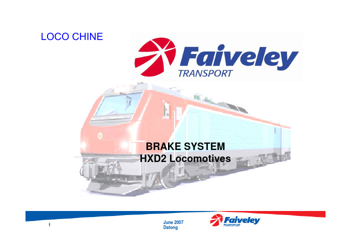
LOCO CHINEBRAKE SYSTEMHXD2 LocomotivesJune 2007General data of the locomotiveNormal service : 2 locomotives coupled togetherLocomotive 1 : master(generator of BP pressure active)Locomotive 2 : slave(generator of BP pressure no active)June 2007Type of brakes•Pneumatic friction brake•Electro-dynamic brake•Automatic parkingbrakeThe pneumatic friction brake is controlled by the driver’s brake valve (Eurotrol).June 2007Brake systemsDual brake pipe modes•Passengers (brake pipe 6 bar)•Freight (brake pipe 5 bar )Dual brake modes•Gradual control•Direct mode releaseJune 2007Brake commandsJune 2007LOCOTROL System•Multiple unit control system, installed on all units (leading & remote)•All traction and braking commands on the leading locomotive are transmitted to the others through the LOCOTROL systemJune 2007June 2007•Generic hardware & software platform called Gemini II •Controls the pneumatic equipment of the Eurotrol •Interfaced through :– A FIP bus to the train computer– A RS422 link to the LOCOTROL•Based on :–Time dependent inputs from the indirect brake manipulator –Brake demand from LOCOTROL systemBCUBCUJune 2007Brake system •dcwvJune 2007Brake system •Block schemeJune 2007June 2007•Receives its input from the BCU •Modulates the BP pressure–Calculates the internal pressure valve RE–Activates the control valves in a closed loop to obtain the desired pilotpressure REEUROTROLEUROTROL •First brake step pressureJune 2007EUROTROL •Brake applicationJune 2007EUROTROL •Brake releaseJune 2007EUROTROL •Stabilisation after braking or releasingJune 2007EUROTROL •Quick releaseJune 2007EUROTROL •Emergency brakeJune 2007EUROTROL •NeutralisationJune 2007June 2007•One distributor valve group per locomotive •This module :–Realises the automatic pneumatic brake,–Distributes air in the RADistributor valve group•Distributor SW4 G/P mode •Operation mode lever (management of BP reference pressure) :–M (freight) position : P BP = 500kPa–V (passenger) position : P BP = 600kPa•2 release modes : gradual & direct release ( RB(IS)RC cock position )June 2007•Cock RB(IS)RC open (switch closed)•Carried out in large flow (manipulator in GD position)•Only if P BP > 300kPa •If VV(RT)RC detectsa ΔP > 20kPabetween BP & R(T)↘RC discharge itselfinside BP↘The distributor is able to release the brake more quickly Direct release modeBrake releaseDirect release mode Brake releaseJune 2007Direct release mode Brake applicationJune 2007•Cock RB(IS)RC closed (switch open)Gradual release mode Brake applicationJune 2007LOCO CHINE DJ4Gradual release modeBrake releaseJune 2007HXD2 LocomotiveBrake releaseFor dynamic brake applicationJune 2007DIRECT BRAKEmanipulator•Controlled by the BCU onrequest of the LOCOTROLsystem, on the remotelocomotiveJune 2007DIRECT BRAKE •Brake applicationJune 2007DIRECT BRAKE •Release positionJune 2007DIRECT BRAKE •Brake cylinder pressure maintainingJune 2007HXD2 LocomotiveEMERGENCY BRAKE•Venting of the RE pilot pressure& of the brake pipeJune 2007EMERGENCY BRAKE•Action on the cabin’s emergencyequipment (push buttons)•Fast venting of the BPthrough a big hole(ø= 25mm)June 2007EMERGENCY BRAKE•Emergency brakingdone by the safety equipmentJune 2007PARKING BRAKE •Spring applied /pressure released type •Under the RA controlJune 2007PARKING BRAKE •The parking brake ventingJune 2007PARKING BRAKE •The parking brake ventingJune 2007PARKING BRAKE •The parking brake isolatingJune 2007Isolation •Parking brake isolationJune 2007•Parking brake isolationJune 2007Isolation •Direct brake isolationJune 2007•Direct brake isolationJune 2007•Brake cylinder isolationJune 2007•Brake cylinder isolationJune 2007Isolation •EUROTROL / CG isolating module (master / slave)June 2007•Eurotrol isolationJune 2007Isolation •Distributor / MP isolationJune 2007Isolation •Distributor / BP isolationJune 2007•MP/CG isolationJune 2007BRAKE PANEL •June 2007BRAKE PANEL •June 2007BRAKE PANEL (prototype)•June 2007。
《制动系培训讲义》PPT课件
培训讲义
2021/8/18
第31页
二、汽车制动系组成及原理
培训讲义
当向顶杆座a施加制动力时,平衡活塞c下移,关闭 排气阀门d,打开进气阀门j,从后桥贮气筒来的气压经 11口进入到A腔,从21口输出到后回路中的弹簧制动气 室的膜片腔。在A腔中的气压通过孔道D进入B腔,作用 在继动活塞f的上部,使继动活塞f下行,同时压缩回位 弹簧,关闭排气阀门h,打开进气阀门g,从前桥贮气筒 来的气压经12口到达C腔,从22口输出到前回路中。
实现汽车减速或停车。
2021/8/18
第3页
一、汽车制动系概述
3、制动系的要求
•具有良好的制动性能 •操作轻便 •制动稳定性好 •制动平顺性好 •散热性好
培训讲义
2021/8/18
第4页
一、汽车制动系概述
培训讲义
4、东风系列重型汽车制动系特点
1、采用先进的气压制动技术:引进德国 WABCO公司的全套制动阀类总成,大大提 高整车的安全性,可靠性,舒适性, 灵敏性。
制动系功用:视需要使汽车减速或在最短的 距离内停车,并保证汽车停放可靠,不至自动 滑溜。
2021/8/18
第2页
一、汽车制动系概述
2、制动系的组成
培训讲义
1、行车制动装置:行驶时减速和停车 2、驻车制动装置:使停驶的车辆驻留原地不动 3、辅助制动装置:基本制动的辅助部分,防止
因制动器过热而降低制动效能。 4、应急制动装置:在行车制动失效的情况下
上行 减小 上升 关闭 打开
2021/8/18
第8页
二、汽车制动系组成及原理
培训讲义
调压阀
作用:使储气筒保持在 规定的气压范围内,并在超 过规定气压后,实现空压 机的卸荷空转,以减小发 动机的功率消耗,延长空压 机寿命。另可向外取气。
制动系统培训——制动系统原理 PPT课件
第二节、全车制动系统分析
空压机将压缩空气经干燥器输到四回路阀。干燥器 将系统工作气压限制在0.87MPa(调压阀切断压力8.5 ± 0.2bar ),系统气压超过此极限时调压阀开启。
四回路保护阀的作用是将前桥制动系统、中后桥制 动系统、停车制动系统和辅助用气系统分成四个完全 独立的回路,当任何一回路发生故障时,可确保其它 三个回路能正常工作。
驻车制动手柄 Parking lever
挂车单独制动手柄 Hand brake lever for trailer
brake
注意: 只有在制动系统压力高于 0.55MPa时,驻车制动信 号灯熄灭后,驻车制动才 可完全解除。
济南卡车股份公司培训基地
中国重汽产品及营销服务培训
注意:
(1)、在制动灯熄灭后,可以操纵各助力系统(如离 合器助力器和副变速箱的换档等)。但在储气筒压力达到 0.7MPa(可在双针气压表上读得)之前,车辆还没有完全 达到适合于行使的状态。只有储气筒压力达到0.7MPa之后, 制动器才能达到所规定的制动性能。
(2)、当车辆停止时,必须拉上手制动! (3)、在起动发动机之前,必须将手制动阀手柄放在 制动位置,否则,制动系压力升高后,原有的驻车制动作 用将消除。
警告:在信号灯熄灭之前切勿开动汽车!
济南卡车股份公司培训基地
中国重汽产品及营销服务培训
弹簧制动缸的紧急解除
❖ 当连接弹簧制动缸的气管路因泄露而造成自行制动时, 只要将弹簧制动缸后端的螺栓拧出到解除位置,即可将 制动解除。
济南卡车股份公司培训基地
中国重汽产品及营销服务培训
1、前桥制动系统 压缩空气经四回路阀后一路不断地向前制动储
电力机车制动系统第六章 法维莱Eurotrol制动系统

BCU闭环控制流程
CPU显示管理
CPU显示允许 用户进入CPU 内部信息区,例 如软件版本和故 障代码,从而执 行特殊操作,如 重置故障和压力 传感器的设置。
综合作用简介
制动系统综合作用大致可分为自动 制动、直通制动、停放制动、无火 回送、故障处理、Locotrol控制的 集成式制动。
制动控制柜 Brake Frame
压缩机 Air Compressor
总风缸 Main Reservoir
制动控制器(大闸) Manipulator
总风管
Main Pipe
列车管 Brake Pipe
制动器 BFC/BFCF
3
制动机主要部件
► 制动机主要包括司机制动控制器、制
动显示屏、司机制动阀、作用阀模块、 BCU(制动控制单元)、备用制动模 块、直通制动模块、停放制动模块、 隔离模块、流量计、分配阀、转向架 中继阀等部件组成。
Eurotrol制动机制动控制柜
Eurotrol制动机司机制动控制器
司机制动控制器包括自动制动控制 器和直通制动控制器,是一个集成 在一起的制动操纵装置,左侧是自 动控制部分,俗称大闸,右侧是直 通制动控制部分,俗称小闸
Eurotrol制动机司机制动控制器
制动显示屏
1.实时显示与制动相关的压力及流量信息, 压力包括均衡风缸、列车管、总风及制动缸 的压力。 2.可以进行制动机模式切换
制动显示屏
司机制动阀
司机制动阀从BCU(制动控制单 元)接受输入信号,然后调整BP (列车管)压力信号,进而作原理
司机制动阀缓解位
司机制动阀快速缓解位
司机制动阀制动位
作用阀模块
紧急制动时快 速排出BP 压 缩空气
HXD2转型培训法维莱制动机课件教程文件
紧急位 (EMER): 手柄至于该位置则产生紧急制动。
迎机教育
独立制动(小闸)有3个位置分别为: 运转位(RUN): 用于缓解机车制动缸。 最大制动位(FULL): 该位用于产生机 车制动缸的最大制动压力,在运转位和 最大制动位之间则产生相应的制动和缓 解。 侧缓位: 将小闸搬至侧面则产生缓解 指令。
名称 紧急排风 隔离塞门
总风隔离塞 门
分配阀上的 机械塞门
位置 正常位 切除位 正常位
切除位 正常位 缓解位
管路的通、断 开通(垂直位) 切除(水平位) 开通(垂直位)
切除(水平位) 手柄垂直位 手柄扳动
作用或使用时机 开通紧急阀通路 切除紧急阀通路
开通总风至过滤器通 路
切除总风至过滤器通 路 控制风缸不通大气
迎机教育
转型培训
HXD2B电力机车转型培训
法维莱制动机
魏志勇
迎机教育
转型培训
一、认识法维莱制动机
法维莱制动机组成
法维莱制动机由制动控制器(大、小 闸)、制动显示屏、制动柜与基础制动 装置组成的。
迎机教育
转型培训
制动控制器的自动制动(大闸) 有6个位置分别为:
运转位 (RUN): 手柄置于该位置则列车管充气至500KPa或 600KPa并使列车管保持在该压力值。
迎机教育
转型培训
低压保护提示:制动系统具有总风低压保护功能,当显示 屏顶部出现“总风低”提示时,不允许缓解。
紧急制动倒计时:机车无论什么原因发生紧急制动后,都 会产生60s倒计时,60s内禁止缓解,制动控制屏的顶部出现 60s倒计时提示信息,当计时结束时,红色信息框不会消失 ,可以进行缓解。
HXD2转型培训法维莱制动机课件

名称 紧急排风 隔离塞门
总风隔离塞 门
分配阀上的 机械塞门
位置 正常位 切除位 正常位
切除位 正常位 缓解位
管路的通、断 开通(垂直位) 切除(水平位) 开通(垂直位)
切除(水平位) 手柄垂直位 手柄扳动
作用或使用时机 开通紧急阀通路 切除紧急阀通路
开通总风至过滤器通 路
切除总风至过滤器通 路 控制风缸不通大气 控制风缸通大气,闸 缸缓解
转向架2 闸缸塞门
位置 正常位 切换位 正常位
切除位
正常位
切除位
管路的通、断 作用或使用时机
开通(垂直位) 正常运用位
切除(水平位) 切除弹停
开通(垂直位)
开通转向架1闸缸通 路
切除(水平位)
切除转向架1闸缸通 路
开通(垂直位)
开通转向架2闸缸通 路
切除(水平位)
切除转向架2闸缸通 路
迎机教育
转型培训
重联位(MU): 在换端作业时,将大闸手柄推重联位, 当手柄推至重联位时,列车管减压至0KPa。
紧急位 (EMER): 手柄至于该位置则产生紧急制动。
迎机教育
独立制动(小闸)有3个位置分别为: 运转位(RUN): 用于缓解机车制动缸。 最大制动位(FULL): 该位用于产生机 车制动缸的最大制动压力,在运转位和 最大制动位之间则产生相应的制动和缓 解。 侧缓位: 将小闸搬至侧面则产生缓解 指令。
迎机教育
转型培训
低压保护提示:制动系统具有总风低压保护功能,当显示 屏顶部出现“总风低”提示时,不允许缓解。
紧急制动倒计时:机车无论什么原因发生紧急制动后,都 会产生60s倒计时,60s内禁止缓解,制动控制屏的顶部出现 60s倒计时提示信息,当计时结束时,红色信息框不会消失 ,可以进行缓解。
- 1、下载文档前请自行甄别文档内容的完整性,平台不提供额外的编辑、内容补充、找答案等附加服务。
- 2、"仅部分预览"的文档,不可在线预览部分如存在完整性等问题,可反馈申请退款(可完整预览的文档不适用该条件!)。
- 3、如文档侵犯您的权益,请联系客服反馈,我们会尽快为您处理(人工客服工作时间:9:00-18:30)。
LOCO CHINEBRAKE SYSTEMHXD2 LocomotivesJune 2007General data of the locomotiveNormal service : 2 locomotives coupled togetherLocomotive 1 : master(generator of BP pressure active)Locomotive 2 : slave(generator of BP pressure no active)June 2007Type of brakes•Pneumatic friction brake•Electro-dynamic brake•Automatic parkingbrakeThe pneumatic friction brake is controlled by the driver’s brake valve (Eurotrol).June 2007Brake systemsDual brake pipe modes•Passengers (brake pipe 6 bar)•Freight (brake pipe 5 bar )Dual brake modes•Gradual control•Direct mode releaseJune 2007Brake commandsJune 2007LOCOTROL System•Multiple unit control system, installed on all units (leading & remote)•All traction and braking commands on the leading locomotive are transmitted to the others through the LOCOTROL systemJune 2007June 2007•Generic hardware & software platform called Gemini II •Controls the pneumatic equipment of the Eurotrol •Interfaced through :– A FIP bus to the train computer– A RS422 link to the LOCOTROL•Based on :–Time dependent inputs from the indirect brake manipulator –Brake demand from LOCOTROL systemBCUBCUJune 2007Brake system •dcwvJune 2007Brake system •Block schemeJune 2007June 2007•Receives its input from the BCU •Modulates the BP pressure–Calculates the internal pressure valve RE–Activates the control valves in a closed loop to obtain the desired pilotpressure REEUROTROLEUROTROL •First brake step pressureJune 2007EUROTROL •Brake applicationJune 2007EUROTROL •Brake releaseJune 2007EUROTROL •Stabilisation after braking or releasingJune 2007EUROTROL •Quick releaseJune 2007EUROTROL •Emergency brakeJune 2007EUROTROL •NeutralisationJune 2007June 2007•One distributor valve group per locomotive •This module :–Realises the automatic pneumatic brake,–Distributes air in the RADistributor valve group•Distributor SW4 G/P mode •Operation mode lever (management of BP reference pressure) :–M (freight) position : P BP = 500kPa–V (passenger) position : P BP = 600kPa•2 release modes : gradual & direct release ( RB(IS)RC cock position )June 2007•Cock RB(IS)RC open (switch closed)•Carried out in large flow (manipulator in GD position)•Only if P BP > 300kPa •If VV(RT)RC detectsa ΔP > 20kPabetween BP & R(T)↘RC discharge itselfinside BP↘The distributor is able to release the brake more quickly Direct release modeBrake releaseDirect release mode Brake releaseJune 2007Direct release mode Brake applicationJune 2007•Cock RB(IS)RC closed (switch open)Gradual release mode Brake applicationJune 2007LOCO CHINE DJ4Gradual release modeBrake releaseJune 2007HXD2 LocomotiveBrake releaseFor dynamic brake applicationJune 2007DIRECT BRAKEmanipulator•Controlled by the BCU onrequest of the LOCOTROLsystem, on the remotelocomotiveJune 2007DIRECT BRAKE •Brake applicationJune 2007DIRECT BRAKE •Release positionJune 2007DIRECT BRAKE •Brake cylinder pressure maintainingJune 2007HXD2 LocomotiveEMERGENCY BRAKE•Venting of the RE pilot pressure& of the brake pipeJune 2007EMERGENCY BRAKE•Action on the cabin’s emergencyequipment (push buttons)•Fast venting of the BPthrough a big hole(ø= 25mm)June 2007EMERGENCY BRAKE•Emergency brakingdone by the safety equipmentJune 2007PARKING BRAKE •Spring applied /pressure released type •Under the RA controlJune 2007PARKING BRAKE •The parking brake ventingJune 2007PARKING BRAKE •The parking brake ventingJune 2007PARKING BRAKE •The parking brake isolatingJune 2007Isolation •Parking brake isolationJune 2007•Parking brake isolationJune 2007Isolation •Direct brake isolationJune 2007•Direct brake isolationJune 2007•Brake cylinder isolationJune 2007•Brake cylinder isolationJune 2007Isolation •EUROTROL / CG isolating module (master / slave)June 2007•Eurotrol isolationJune 2007Isolation •Distributor / MP isolationJune 2007Isolation •Distributor / BP isolationJune 2007•MP/CG isolationJune 2007BRAKE PANEL •June 2007BRAKE PANEL •June 2007BRAKE PANEL (prototype)•June 2007。