二重齿轮箱使用维护说明书
(整理)齿轮箱的维护与故障分析
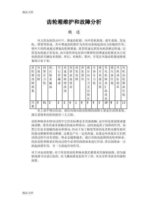
齿轮箱维护和故障分析概述风力发电机组由叶片、增速齿轮箱、风叶控制系统、刹车系统、发电机、塔架等组成。
其中增速齿轮箱作为其传动系统起到动力传输的作用,使叶片的转速通过增速齿轮箱增速,使其转速达到发电机的额定转速,以供发电机能正常发电。
高可靠性和良好的可维修性的增速齿轮箱是风力发电机组的关键技术保障。
所以,对海阳、莱州、开发区风场齿轮箱故障现象统计如下表:液压系统和齿轮的损坏三大方面。
齿轮和轴承在转动过程中它们实际都是非直接接触,这中间是靠润滑油建成油膜,使其形成非接触式的滚动和滑动,这时油起到了润滑的作用。
虽然它们是非接触的滚动和滑动,但由于加工精度等原因是其转动都有相对的滚动摩擦和滑动摩擦,这都会产生一定的热量。
如果这些热量在它们转动的过程中没有消除,势必会越集越多,最后导致高温烧毁齿轮和轴承。
因此齿轮和轴承在转动过程中必须用润滑油来进行冷却。
所以润滑油一方面起润滑作用,另一方面起冷却作用。
对于风电齿轮箱,对于所有的齿轮和轴承我们都要采用强制润滑。
因为强制润滑可以进行监控,而飞溅润滑是监控不了的。
从安全性考虑采用强制润滑。
一、风电齿轮的损坏类型及其判断下表为齿轮轮齿的主要故障形式及其原因根据裂纹扩展的情况和断齿原因断齿包括过载折断(包括冲击折断)疲劳折断以及随机断裂等断齿常由细微裂纹逐步扩展而成。
疲劳折断发生从危险截面(如齿根)的疲劳源起始的疲劳裂纹不断扩展,使轮齿剩余截面上的应力超过其极限应力,造成瞬时折断其根本原因是轮齿在过高的交变应力重复作用,在疲劳折断处,是贝状纹扩展的出发点并向外辐射产生的原因有很多。
主要是材料选用不当,齿轮精度过低,热处理裂纹,磨削烧伤,齿根应力集中等等因此在设计时需要考虑传动的动载荷谱,优选齿轮参数,正确选用材料和齿轮精度,充分保证加工精度消除应力集中集中因素等等。
过载折断总是由于作用在轮齿上的应力超过其极限应力,导致裂纹迅速扩展,常见的原因有轴承损坏突然冲击超载轴弯曲或较、大硬物挤入啮合区等断齿断口有两种形式一种呈放射状花样的。
A-1 齿轮箱的安装操作及维护说明

安装、操作和维护说明书保证书注意:保证范围内的维护和维修必须由NUTALL授权的服务商进行,否则本保证无效。
NUTTALL GEAR保证它所提供的产品自安装起一年内,或交付给买方18个月内,在材料上和工艺上都不会有任何缺陷。
一经收到设备也已按照NUTTALL的推荐和工业惯例标准储存、安装、运行和维修的书面通知,如发现任何不合格之处,NUTTALL将自行选择予以修复或更换,条款为F.O.B工厂交货。
保证中规定是唯一的,取代所有其他保证,不论是法定的、明示的或暗示的(包括所有机械保证和特殊目的适用性以及处理过程或贸易过程的保证),但涉及权属和专利侵权的情况除外。
上述补救措施将构成NUTTALL对买方根据合同投诉侵权(包括过失),或其它关于产品的投诉的全部责任的履行。
连接的转动部件系统-原动力和附件,齿轮单元和从动设备-必须兼容;避免临界速率、扭矩或其它类型的振动,在运行范围内,不管摆动源和/或原因。
NUTTALL GEAR公司的责任限定在提供正常商务水平的引起摆动的齿轮单元,不负责由于转动部件不兼容引起的不正确的运行或驱动系统的故障,也不负责分析原因。
除非NUTTALL GEAR同意作分析,一般买方、制造商和设计者对系统负责任,NUTTALL GEAR不负责任何摆动性质的分析。
提供安装电机/齿轮耦合器的单元应由安装人员负责校正,NUTTALL GEAR 验证电机和齿轮可以校正,但是不负责最后的校正工作,因为运输途中可能引起变化,基础的情况也不同。
用户负责提供和安装护板或其它保护操作人员的安全设备,尽管该安全设备不由卖方随设备提供。
NUTTALL,以及其各级承包商和供货商,不负责合同、侵权(或过失)、其它财产或设备的损失、损坏,利润或收益的损失、使用设备或动力系统的损失、成本、购买价格、更换动力、临时设备(包括使用当前设备发生的额外费用)、买方客户的投诉、以及特定的、间接的、引发的或引起的任何损失。
这里规定的买方补救措施是独占的,对于合同、与合同相关的事项,如违约等,或生产、销售、交货、零售或使用按合同交付的设备,不论是否在合同中、是否侵权(或过失)或其他,NUTTALL的责任不超过所投诉设备或零件的价格。
齿轮箱操作手册.
用以驱动风力发电机的PPSC1290-MY型齿轮箱操作手册Jahnel-Kestermann Getriebewerke 有限公司Hunscheidtstrasse 街116号44789 Bochum市(德国)操作手册内容目录技术数据----------------------------------------------------安全------------------------------------------------------------100-0003-01 综述------------------------------------------------------------100-0003-02 运输------------------------------------------------------------100-0012-03 结构和功能---------------------------------------------------350-0019-04 装配-------------------------------------------------------------100-0006-05 准备工作-------------------------------------------------------100-0004-06 启动-------------------------------------------------------------100-0001-07 运行-------------------------------------------------------------100-0001-08 维护-------------------------------------------------------------100-0006-11 推荐的润滑剂-------------------------------------------------100-0006-11在运行之前请仔细阅读并遵守操作手册和安全措施1,采购订货数据客户名称客户编号合同编号2,订货数据齿轮箱型号-------------------------------------------------PPSC1290-MY 外形尺寸图纸编号-----------------------------------------零件图纸编号----------------------------------------------零件表编号------------------------------------------------- 40 267 691 00 订货编号3,齿轮箱数据3.1 齿轮箱使用范围齿轮箱应使用在满足规范中规定的载荷和条件的风力发电机中。
齿轮箱说明书
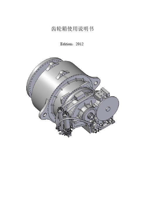
齿轮箱使用说明书Edition:2012版本升级记录从Edtion:2011升级到Edtion:2012版本的主要内容:1.在6.4章节中增加了严禁对齿轮箱进行敲击装配的提醒;2.在8.2章节中增加了对风机传动链长时间锁死对齿轮箱会造成严重损害的重要提示;3.在9.1章节中进一步明确了电机泵的启动关闭控制流程,删去了单速电机泵的控制流程;4.在9.2章节中进一步明确了风扇的启动和关闭控制流程,删去了单速风扇或水冷的的控制流程;5.在10章中重新整合本章的内容,并增加了10.9级螺栓预紧力矩检查标准。
目录1 前言 (5)2 开箱 (6)3技术参数 (7)3.1 铭牌 (7)3.2 应用领域 (7)4 安全事项 (8)4.1正常使用 (8)4.2客户义务 (8)4.3环境保护 (9)4.4特殊危险 (10)5 运输和储藏 (11)5.1运输 (11)5.2 储藏 (12)6齿轮箱的安装 (14)6.1 拆箱 (14)6.2 排油、去除防腐剂 (14)6.3高速轴连轴器的安装 (14)6.4 加油 (16)6.5 连接电路 (16)6.6 机舱试车前的检查 (16)6.7 机舱试车 (17)6.8 齿轮箱随机舱的运输 (17)7齿轮箱拆卸 (18)7.1拆除高速轴连轴器 (18)7.2防腐防锈处理 (18)8启动与停机 (19)8.1启动 (19)8.2齿轮箱的停机 (20)9监控要求 (22)9.1 电机泵的控制 (23)9.2 风扇或水冷的控制 (24)9.3运行温度 (24)9.4 油位检查 (25)9.5 取油样 (26)9.6油压 (26)9.7 齿轮箱内部检查 (27)10维护和修复 (28)10.1中分面及齿圈螺栓的检查 (28)10.2必须维护的项目 (29)10.3齿轮箱常见故障 (30)11润滑系统 (32)11.1润滑油 (32)11.2 换油 (33)11.3更换滤芯 (33)11.4安装滤芯 (34)12 重要事项 (35)12.1 空气滤清器 (35)12.2 滤芯 (35)12.3 润滑油 (35)1 前言用户在安装使用前请详细阅读本说明书。
风机齿轮箱的 使用和维护

风力发电机齿轮箱的使用与维护王朝阳一、基本原理及结构风力发电机是将风能转化为电能的机械装置。
目前可分为:有齿轮箱和无齿轮箱两类风力发电机。
商业化的风力发电机以有齿轮箱的居多。
齿轮箱是风机中的一个重要部件,它承担着将风轮的转速增加到发电机转速的任务,所以该齿轮箱也称为增速齿轮箱。
风力发电机用齿轮箱种类繁多,从传动方式来分,齿轮箱可划分为行星齿轮箱,平行轴齿轮箱,混合式(行星+平行轴)齿轮箱。
行星齿轮箱:如万电600KW为两级行星结构。
平行轴齿轮箱:如浙江机电院的250KW风机为两级平行轴结构,美德660KW为三级平行轴功率双分流结构。
混合式:该类齿轮箱为使用最广泛的结构类型,图1.1为其典型结构图。
具体可分为:1.金风600KW、Vestas V47、Nordex N43、保定惠阳1000KW等均为此类结构----一级行星(NGW)+两级平行轴结构;2.金风750KW,浙江机电院750KW为一级行星(NW)+一级平行轴结构;3.大重1500KW为两级行星(NGW)+一级平行轴结构。
图1.1 齿轮箱结构简图叶轮的转矩通过主轴传入齿轮箱行星架,行星级的太阳轮通过花键与平行级相联,经平行级齿轮将转矩传给发电机。
二、齿轮箱的使用与维护在风力发电机中,齿轮箱是最重要的部件之一,也是目前故障率最高的部件之一,正确的使用与维护可以减少故障率,延长其使用寿命。
1. 齿轮箱的安装1.1通常齿轮箱厂家在供货时为整体供货,在现场不必进行重新解体装配。
1.2齿轮箱起吊时应有防护措施,防止其表面被钢丝绳等物碰伤。
1.3 齿轮箱的输出轴(高速轴)采用联轴器连接,安装时应严格找中,其对中误差必须控制在弹性联轴器允许值的下限以内,一般应≤0.20mm,角度误差≤30″。
(弹性联轴器允许的对中偏差是用于补偿在工作过程中由于受载、温升和离心力所产生的变形,及无法避免的制造和对中偏差的并不是安装的允许偏差,要求安装的允许偏差≤0.05mm)。
齿轮箱说明书

齿轮箱使用说明书Edition:2012版本升级记录从Edtion:2011升级到Edtion:2012版本的主要内容:1.在6.4章节中增加了严禁对齿轮箱进行敲击装配的提醒;2.在8.2章节中增加了对风机传动链长时间锁死对齿轮箱会造成严重损害的重要提示;3.在9.1章节中进一步明确了电机泵的启动关闭控制流程,删去了单速电机泵的控制流程;4.在9.2章节中进一步明确了风扇的启动和关闭控制流程,删去了单速风扇或水冷的的控制流程;5.在10章中重新整合本章的内容,并增加了10.9级螺栓预紧力矩检查标准。
目录1 前言 (5)2 开箱 (6)3技术参数 (7)3.1 铭牌 (7)3.2 应用领域 (7)4 安全事项 (8)4.1正常使用 (8)4.2客户义务 (8)4.3环境保护 (9)4.4特殊危险 (10)5 运输和储藏 (11)5.1运输 (11)5.2 储藏 (12)6齿轮箱的安装 (14)6.1 拆箱 (14)6.2 排油、去除防腐剂 (14)6.3高速轴连轴器的安装 (14)6.4 加油 (16)6.5 连接电路 (16)6.6 机舱试车前的检查 (16)6.7 机舱试车 (17)6.8 齿轮箱随机舱的运输 (17)7齿轮箱拆卸 (18)7.1拆除高速轴连轴器 (18)7.2防腐防锈处理 (18)8启动与停机 (19)8.1启动 (19)8.2齿轮箱的停机 (20)9监控要求 (22)9.1 电机泵的控制 (23)9.2 风扇或水冷的控制 (24)9.3运行温度 (24)9.4 油位检查 (25)9.5 取油样 (26)9.6油压 (26)9.7 齿轮箱内部检查 (27)10维护和修复 (28)10.1中分面及齿圈螺栓的检查 (28)10.2必须维护的项目 (29)10.3齿轮箱常见故障 (30)11润滑系统 (32)11.1润滑油 (32)11.2 换油 (33)11.3更换滤芯 (33)11.4安装滤芯 (34)12 重要事项 (35)12.1 空气滤清器 (35)12.2 滤芯 (35)12.3 润滑油 (35)1 前言用户在安装使用前请详细阅读本说明书。
齿轮箱操作控制说明书
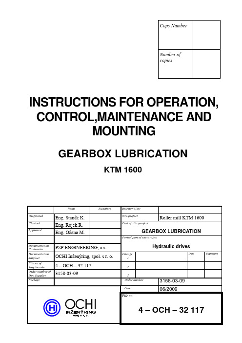
INSTRUCTIONS FOR OPERATION, CONTROL,MAINTENANCE ANDMOUNTINGGEARBOX LUBRICATIONKTM 1600CONTENT0. INTRODUCTION 31. EQUIPMENT DESCRIPTION 3 1.1 Technical parameters 3 1.2 Packaging, transportation, conservation 3 1.3 Mounting 41.4 Documentation 42. DESCRIPTION OF FUNCTION 43. ELECTRIC CONTROL 4 3.1 Electric appliances 43.2 Interlocking, signaling, control 54. PUTTING INTO OPERATION 5 4.1 Oil filling of gearbox 5 4.2 Flushing and testing 5 4.3 Working pressure set up 6 4.4 Flow rate signaling 6 4.5 Pressure control 6 4.6 Oil filtration 6 4.7 Temperature control 64.8 Level control 65. EQUIPMENT OPERATION 66. EQUIPMENT MAINTENANCE 77. SPARE PARTS AND GASKETS 8 7.1 Instructions for spare parts and gaskets ordering 80. INTRODUCTIONWe provide you this accompanying documentation to supplied equipment. You will find technical parameters and instructions for correct putting the equipment into operation, for control and maintenance.1. EQUIPMENT DESCRIPTIONThe equipment consists of the following parts : - aggregate- pipe distributionLubrication aggregate is a source of lubrication oil. It consists of the frame on which lubrication unit is placed (pump and electric motor), filter, cooler, contact thermometer, safety valve and flow rate switch.Pipe distribution is made with the pipes connected with flat flanges and closing valves. Pipe distribution is connected to the gearbox with hoses or rubber compensators for vibration compensation. On the gearbox body there is a level gauge with level switch and ball valve for discharge.Lubrication function is shown on the functional diagram dr.no. 4-OCH-31 011.1.1 Technical parametersLubrication aggregate∙Tank capacity -∙Delivered quantity 43 dm3min-1∙Safety pressure 10 bar∙Max. input 1,5 kW∙Electric motor revolutions 1400 min-1∙Working liquid Mineral oil ISO VG 100 ( according to DIN 51 519 ) ∙Working temperature 20 - 55 °C.∙Filtration rate 25 μm∙Heating In gearbox – 2 x 750 W∙Cooling Water cooler, P CH=18 kWat ∆t=25°C∙Electric motors voltage ~400 V, 50 Hz∙Elements voltage 24 V DC1.2 Packaging, transportation, conservationAll the parts of lubrication system are conserved with the lubrication oil and the parts of pipe distribution and the outlets from the aggregate and separate elements are plugged for transportation. Lubrication aggregate is possible to replace only for the lower part of the frame.1.3 MountingEquipment mounting is performed by the specialists for lubrication equipment or by the staff properly trained. Mounting shall be done in accordance with attached technical documentation.All parts of the pipe distribution shall be properly cleaned prior to mounting.The lubrication aggregate is mounted to the machine prior to the assembly of pipe distribution and is fixed with anchor bolts to the footing. After proper cleaning of the inlets the lubric. aggregate is connected with the gearbox by means of pipe distribution. Connection spots are shown on the lubrication aggregate layout drawing dr.no. 3-OCH-31 128and piping distribution is connected according to the functional diagram dr.no. 4-OCH-31 011.Mounting shall be documented with the assembly book mentioning the firm that performed mounting.1.4 DocumentationThe lubrication aggregate is usually supplied with :∙The instructions for operation, control, maintenance and mounting∙functional diagram∙specification of elements∙layout drawing of lubrication aggregate∙motor list2. DESCRIPTION OF FUNCTIONLubrication liquid is sucked with gear hydrogenerator (pos. 103) from the gearbox housing. Liquid flows further under pressure about 1÷3 bar through double filter (pos. 107) and the cooler (pos. 119) back to the gearbox housing on three lubricated spots. Filter clogging signal is electric.Pressure part of lubrication circuit is secured with pressure about 10 bar by means of pressure valve mounted on gear hydrogenerator (pos. 103).Working pressure is possible to control visually by means of manometer (pos. 109).Flow rate of lubrication oil is controlled with flow rate switch (pos. 114).Liquid temperature in gearbox is remote controlled with temperature sensor (pos. 117).Minimal oil level in the gearbox is signaled with level switch (pos. 122) mounted on gearbox.Remote control of pickup values is terminated on control panel.3. ELECTRIC CONTROL3.1 Electric appliancesPos. 102 - electric motor FCPA 90 L-4, 1,5 kW, 1400 min-1, 400 VPos. 106 - terminal switch DIN EN 50 041 – A1 250 VPos. 107 - filter clogging indicator AE.70.P.-.B, 3 VA, 24 VPos. 114 - flow rate sensor SI5000, 0,4 A, 24 VPos. 117 - temperature sensor T1005, 4÷20 mA, 230 VPos. 119 - water valve AB 21-23 / G3/4-G24 Z4, 12W, 24 VDCPos. 122 - level switch SNK 176 V-C-O-12-R, 0,5A, 24 VPos. 124 - heating element type 14070, 750 W, 230 V3.2 Interlocking, signaling, control-oil level drop in the gearbox below MIN –level switch SL1=0(pos.122) –electric motor run interlock M1 (pos.102) – FAILURE-closed ball valve SQ1=0(pos.106) –electric motor run interlock M1(pos.102) –FAILURE-insufficient lubrication – flow rate switch SQ2=0(pos.114) for a period more than 2 min. – electric motor run interlock M1 (pos.102) – FAILURE-filter clogging SF1=1 (pos.107) – signaling-low oil temperature (<15︒C) – temperature sensor BT1 (pos.117) – electric motor run interlock M1 (pos.102) – FAILURE-high oil temperature (>55︒C) – temperature sensor BT1 (pos.117) – water valve Y1=1 switched (pos.119)-high oil temperature (=60︒C) –temperature sensor BT1(pos.117) - visualization - warning-very high oil temperature (>70︒C) –temperature sensor BT1(pos.117) - electric motor run interlock M1 (pos.102) – FAILURE-oil heating – is automatically on at electric motor start M1 (pos.102) in case that oil temperature in the gearbox BT1 < 25 °C. It is off at BT1 = 35 °C4. PUTTING INTO OPERATIONPutting into operation is performed at the customer after it is connected to the machine lubrication and electric circuit. After transportation it is necessary to check the assembly of the aggregate parts, especially seating of electric motors and pumps.Putting into operation shall be done only by the equipment fabricator or by the persons trained by the fabricator who will be approved by the fabricator in written.During putting into operation the whole course of putting into operation shall be documented in the book. Putting into operation shall be done in accordance with the following points:4.1 Oil filling of gearboxGearbox filling shall be done with filtration filling unit with possibility of filtration min. 25 μm. Prescribed liquid is mentioned in technical parameters p.1.1. Level shall be checked on the level indicator (pos. 122)4.2 Flushing and testingPrior to putting into operation it shall be checked, whether the direction of electric motor turning corresponds to the data on the pump plate, on right-handed pump the direction of turning is in clockwise direction, with a view from electric motor to the pump. Pressure valve is released. Having performed the check, start the pump and let it run without pressure. During commissioning check and refill working fluid.After flushing it is necessary to take off oil sample from the gearbox to estimate liquid purity. If oil meets purity class 9 according to NAS 1638, it is possible to start with the lubrication equipment testing.Flushing shall be done also after long shut-downs and bigger repairs that involve pipe distribution.4.3 Working pressure set upMax. working pressure in lubrication circuit shall be set up by means of safety valve to 10 bar. Pressure is adjusted with the screw turning ( supply – pressure raise).Maximal working pressure can be adjusted at closed closing valve (pos. 120) at the outlet from the lubrication aggregate.4.4 Flow rate signalingFlow rate switch (pos. 114) signals liquid flow rate at the outlet from the aggregate.4.5 Pressure controlPressure can be controlled by means of built-in pressure gauge (pos. 109).4.6 Oil filtrationOil filtration is assured with double outlet filter (pos. 117). Filter is equipped with electric sensor of clogging and by-pass valve in case of clogging. Filtration degree is mentioned in technical parameters.Filtration insert substitution shall be done in case of :- impurity indicator signal (for more than 2 minutes)- after the first 500 hours after putting equipment into operation or once a year (according to the laboratory oil analysis – performs specialized firm ) -oil substitution4.7 Temperature controlOil temperature is measured with temperature sensor (pos. 117). Oil temperature can be checked with thermometer (pos. 118) – only when the pump runs.4.8 Level controlOil level height is controlled with level switch (pos. 122) that sends electrical signal if oil level in the gearbox is minimal and interlocks the drive, when oil level drops below emergency level.5. EQUIPMENT OPERATIONThe equipment operators shall be familiar with:a) the work of lubrication circuit in accordance with the functional diagramb) have basic knowledge about maintenance of lubrication equipmentc) safety rules and principles of safe work during manipulation with mineral oilsd) the function of lubrication elements and the way of their controlThe operators duties are :-performance of preventive examinations of equipment-control of hydraulic elements at adjustment-determination of requirements for equipment maintenance-maintain the book documenting running of the lubrication equipment and performed repairs6. EQUIPMENT MAINTENANCEMaintenance is an important condition for operation of the lubrication equipment. Any interferences for the maintenance of equipment are performed when it is out of operation (without pressure) and by the workers specially assigned for this work who are responsible for this work and properly trained for this activity.A part of the equipment maintenance Is the implementation of so called inspection system, duly documented with the book and checked, in which the following data are especially mentioned :-examination of equipment, in particular connections of pipe distribution-record of finding the first drop or oil leakage and the way of removal-assignment of repair date and responsible worker-confirmation about performance of the repair and its control-parallel oil check performed by specialized firm at least once a month and oil refill, as requiredImplementation of the inspection system is a necessary presumption foreventual claim procedure.Prior to eventual repair all lubrication equipment shall be cleaned in order to prevent from dirty entry into oil during repair. All the repairs are performed when agreed with the equipment operators.Especially for the first 3 months after passing-over the equipment to the User it is necessary to follow-up leaks of the pipe distribution and the connections shall be regularly retightened.At each long equipment shut-down it is useful :-to check the level height, or refill oil (only assigned quality with auxiliary hydrogenerator through the filter 25 m)At each repeated start :-to check oil level-to check filter cloggingFurthermore, during operation it is necessary to follow-up :-operation oil temperature-equipment noise7. SPARE PARTS AND GASKETSFor the equipment it is possible to order from the firm OCHI –INŽENÝRING, s.r.o. any spare parts or gaskets in accordance with the specification of elements dr.no. 4-OCH-31 129.7.1 Instructions for spare parts and gaskets orderingWhen ordering the spare parts you must mention :-production number of aggregate and number of the order as per the plate-date of production-name and marking of the element or the gasket in accordance with the specification of elements-number of pieces。
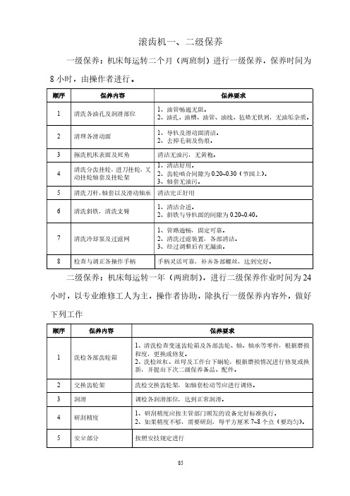
滚齿机一、二级保养操作与维护规程
清洁无油污,无黄袍。
清洗分齿挂轮,进刀挂轮,叉 1、清洁好用。
4 动挂轮轴套及挂轮架
2、齿轮啮合间隙为 0.20~0.30(节园上)。
3、轴套无油污。
5 清洗刀杆,轴套以及滑动轴承 清洁完正好用
6 清洗斜铁,清洗支臂
1、清洁合适。 2、斜铁与导轨面的间隙为 0.20~0.40。
7 清洗冷却泵及过滤网
滚齿机一、二级保养ຫໍສະໝຸດ 一级保养:机床每运转二个月(两班制)进行一级保养,保养时间为
8 小时,由操作者进行。
顺序
保养内容
保养要求
1 清洗各油孔及润滑部位
1、油管畅通无阻。 2、油孔、油槽、油管、油线、毡垫无铁屑,无油垢杂质。
2 清理各滑动面
1、导轨及滑动面清洁。 2、去掉毛刺及伤痕。
3 擦洗机床表面及死角
5 安全部分
按照安技规定进行
85
1、管路通畅,固定可靠。 2、清洗过滤装置,各部清洁。 3、经过调整后有无漏油。
8 检查与调正各操作手柄
手柄灵活可靠,补齐各部螺丝,达到完好。
二级保养:机床每运转一年(两班制),进行二级保养作业时间为 24
小时,以专业维修工人为主,操作者协助,除执行一级保养内容外,做好
下列工作
顺序
保养内容
1 洗检各部齿轮箱
2 交换齿轮架 3 润滑 4 研刮精度
保养要求
1、清洗检查变速齿轮箱及各部齿轮、轴、轴承等零件,根据磨损 程度,更换或修复。 2、洗检丝杠、丝母及工作台下蜗轮,根据磨损情况进行修复或换 新,并提出下次二级保养备品、配件。
洗检交换齿轮架,如轴套松动等应进行调修。
调检各润滑部位,达到正常润滑。
1、研刮精度应按主管部门颁发的设备完好标准执行。 2、如果精度不够,需要研刮,每平方厘米 7~8 个点(要均匀)。
- 1、下载文档前请自行甄别文档内容的完整性,平台不提供额外的编辑、内容补充、找答案等附加服务。
- 2、"仅部分预览"的文档,不可在线预览部分如存在完整性等问题,可反馈申请退款(可完整预览的文档不适用该条件!)。
- 3、如文档侵犯您的权益,请联系客服反馈,我们会尽快为您处理(人工客服工作时间:9:00-18:30)。
开关
操作
设置 设置
点
齿轮装置 电阻 S1.1255 45°C 冷却器70: 风扇打开
入口处的 温度
↑
油温
计
35°C 冷却器70: 风扇关闭
↓
65°C 70°C ↑
↑
轴承温度
S1.1256 S1.1254
85°C 95°C ↑ ↑
齿轮箱油
S1.1253
温度
温度开关 温度 S1.1253 0°C 油泵启动
73,6 16,642
73,6 18,826
17,3 5,997
17,3 4,434
277
82,166
277
82,166
1800 294,339
1800 341,087
1800 341,087
294
34,654
f_out Hz 9,693 12,803 15,526 5,227 3,624 70,142 70,142 215,661 258,913 258,913 24,185
调节
↑
70°C 80°C
10/23
1.5MW风电增速机操作说明书
装置
35°C 浸没式加热器关闭
↑
33°C 浸没式加热器开启
↓
油泵压力 压力 S1.1258
传感
器
差压过滤 污染 S1.1250
器
指示
器
在齿轮装 压力 S1.1259 1.5 bar 启动电泵
置入口处 传感
↓
润滑油的 器
压力
3 .5bar 停用电泵
Hale Waihona Puke f1/minHz
转子
19,0
0,32
行星轴
80,8
1,35
恒星/传动齿
304,1
5,07
轮
传动小齿轮
1800,0
30,00
8/23
1.5MW风电增速机操作说明书
齿轮齿激励频率
f
Hz
空心抡-行星齿
25,6
行星轴-恒星齿
106,4
传动齿轮级
1110,0
滚柱轴承的激励频率
n
f_in
f_out
2*f_rolel f_cage
14/23
1.5MW风电增速机操作说明书
见下表。每级载荷试运转之后要观察齿轮啮合。
时间[min]
载荷等级
60
1/3 标准载荷
120
2/3 标准载荷
240
标准载荷
满载荷运行之后,齿轮的接触要符合设计要求。如果出现异常情
最低值 10.00
9.10
额定值 19,04
17,3
最高转速[rpm]
最高值 26
26
空载转速[rpm]
空载
0…2
额定转速[rpm]
1800
传动比
94.54
104.02
冷却[制冷]能力 [kW]
25
油量 [l]
约390
润滑油量[l/min]
67
润滑油牌号
Shell Omala HD
320(new foemulation)
位移原因 热位移 弹性位移(满载荷) 总位移
x [mm]
-0.75 0.00 -0.75
y [mm]
-0.15 0.85 0.7
z [mm]
0.15 0.85 1.0
在联轴器的轴向调整时要考虑到总的位移量,以及转轴的轴向热 膨胀,。
九 、 试 运 转 必须立即通知制造厂家试运转的日期!
13/23
l 正确的使用还包括遵守制造商规定的安装、拆卸、调试、操 作和维护的相关规则。
l 假如对影响安全(比较高的噪音水平、比正常温度高的温度 等)的齿轮装置做改动,必须马上说明其原因以便消除错误。 同时,必须向系统操作者通报这一变动情况,操作人员必须 负责做这项工作。
l 未经批准不得对齿轮箱进行改进。尤其是禁止添加或去除部 件。
虑连接件的操作偏差(基础,转子轴,发电机轴)。 坐标系
发动机的偏移量按图 4-1 图示方向定义如下: • 正 x-方向:转子方向的纵向转子轴 • 正 y-方向:水平轴,朝转子左方 • 正 z-方向:垂直轴,朝上方向
图 4-1: 发动机的坐标示意图 扭矩臂
弹性轴承座套的扭矩臂在转子轴和齿轮装置传动轴的同一平面。
2/23
1.5MW风电增速机操作说明书
一 、 概 述 : 1.5MW 增速箱是用于风力发电机组中的增速装置,其工作效率
可达 97%以上。风电增速齿轮箱主要由箱体、空心输入轴、力矩支撑、 内齿圈、太阳轮、行星轮、齿轮、齿轮轴、轴承等零件组成。
增速箱包含一个行星齿轮级和一个圆柱齿轮级的两级传动。行 星齿轮的特点是有一个中间双联齿轮,这也是增速机最有特点的地方; 整个齿轮装置与转子轴刚性联接,作为转子轴的第二支承(活动支承), 圆锥滚子轴承可以很方便地调整齿轮装置的啮合侧隙。
12/23
1.5MW风电增速机操作说明书
所以不出现 z-方向的热位移。工作温度下与转子固定轴承有关的齿轮 装置轴向偏移如下:
∆x = -0.25mm ︱∆y ︱= 0.53mm;x - 轴的两个方向 当对弹性元件的轴向调整时都要考虑到这些偏移量,以及转子轴 向的热膨胀。 发电机 发电机的调整要考虑操作温度时的热位移和弹性元件的弹性位 移。 下表表明了分别和总的齿轮从动轴与转子固定轴承有关的位移。 在发电机轴与齿轮装置连接时要考虑到总的位移量,以及发电机轴的 位移。
齿轮装置的驱动从转子轴开始,经由空心输入轴到齿圈。行星齿 轮架和壳体为一体,因此不旋转。
二 、 声 明 l 齿轮装置交付时箱体内无润滑油。 l 齿轮装置外表涂有特殊油漆,法兰、轴端涂有防锈油。 l 输入转向及输出转向均有转向标牌,且用箭头表示。 l 齿轮装置的可调部位在出厂前均已调定(如阀件、喷嘴)。在
↑
14 bar ↑
2.5 bar ↑
0.9 bar 0.7 bar↓ ↓
八 、 调 整 总则
齿轮装置的调整要用弹性轴承座套来进行且对发动机要考虑操作
11/23
1.5MW风电增速机操作说明书
连接点重定位置。造成这些位移的原因是: • 热偏移, • 弹性轴承座套的位移。 列出的偏差和偏移值完全参照齿轮装置的连接点。调整时也要考
1.5MW风电增速机操作说明书
1 准备 启动设备之前,必须核查齿轮装置的油位;见部分 6。整个油系
统必须冲洗。应该使用新的干净油(润滑;见部分 6)填充冲洗。 油系统的冲洗必须是油的纯度获得规定的技术数据(部分 2)为
止。 由于行星齿轮油腔的润滑功能压力腔的作用,可以在润滑系统故
障时,在一定的时间内为齿轮箱提供润滑,压力腔容积大约为 100L。 根据机械设备运行一般规程,润滑系统应先于齿轮箱启动,考虑有 100L 的油在压力腔中,如果没有停机时的间歇工作制度,润滑系统 应先于齿轮箱启动 10 分钟~30 分钟(时间根据系统温度会有所不同), 待齿轮箱润滑压力达到规定值后方可运转齿轮箱。因为如果长时间停 机后,突然启动齿轮箱会因润滑油没有充分到达各润滑点而造成齿轮 箱齿轮和轴承的严重伤害。 2 试运转
1.5MW风电增速机操作说明书
1.5MW风电增速机 操作说明书
编制:李学明 审核:田川宝 批准:吕万铭
二重集团(德阳)重型装备股份有限公司
1/23
1.5MW风电增速机操作说明书
目录
一. 概 述 二 . 声 明 三 . 运 输 、 保 管 和 安 装 四. 基 本 数 据 五. 加 热 六 . 运 动 齿 轮 齿 的 激 励 频 率 七 . 齿 轮 装 置 转 换 开 关 和 监 测 仪 器 八 . 调 整 九 . 试 运 转 十 . 维 护 和 润 滑
特殊情况下现场可作进一步调整。 l 不允许超出给定的工作特性范围进行操作。 l 必须严格遵守操作说明以避免损坏齿轮装置和由此引起的停
机。 l 必须严格按照齿轮装置的技术参数。超出这一范围的任何使
用被认为是不正确的使用。制造商不负责因此而导致的损坏, 操作者对这种违规操作承担责任。
3/23
1.5MW风电增速机操作说明书
24,805
2,213
9/23
1.5MW风电增速机操作说明书
七 、 齿 轮 装 置 转 换 开 关 和 监 测 仪 器
安装所有仪器,以便它们防油防水。将它们接到共享终端盒中。
数据放大器和逻辑开关不属于交货部件的范围。开关和报警点见表
2-1。
装置、开关和报警点
参数
装置 编号 开关功能
报警 系统停止
压。 l 未经许可,擅自拆开齿轮箱,本公司恕不承担责任。 三 、 运 输 、 保 管 和 安 装 l 齿轮箱运输、保存时应小心操作,避免粗暴放置所带来的损害。 l 齿轮箱运输时用专用销轴固定输入法兰,防止低速振荡对齿轮
箱内部件的损坏。
4/23
1.5MW风电增速机操作说明书
l 起吊整台齿轮箱时必须同时用箱体上的 3 个专用吊耳孔进行 起吊。
2*f_rolel f_cage
Hz
Hz
7,415
0,138
9,252
0,533
12,500
0,555
4,002
0,134
2,734
0,129
58,097
2,126
58,097
2,126
189,836
12,686
207,458
12,946
207,458
12,946
22,588
2,015
轴的转速频率
n
77,028
63,801
2,334
304
90,233
77,028
63,801
2,334
1800 294,339