美国omega欧米茄容积式流量计简介
OMEGA FPD 系列流量计说明书

1
IMPORTANT INFORMATION
▲!
Please read this information carefully use, confirm the fluid to be used is compatible with the meter or consult with OMEGA for advice.
To prevent damage to the meter, slowly fill the system with fluid. This will prevent damage caused by air purge.
NOTE: Failure to do this could damage the meter.
Installation................................................... 2
Operation.................................................... 3
Electrical Connections................................ 4
NOTE: When a strainer is installed it should be regularly inspected and cleaned. Failure to keep the strainer clean will dramatically effect flowmeter performance.
INSTALLATION
1. OMEGA recommends that when setting up pipework for meter installations, a bypass line be included in the design. This provides the ability for a meter to be removed for maintenance without interrupting production. (See Figure 1)
OMEGA FTB-4100A 流量计说明书
FTB-4107A-P 195 0.22 11.0 20.0 3⁄4 MNPT 257 (10.1) 77.0 (3.03) 69.9 (2.75) 3.6 0.6 (1.4) 93.3 (200)
FTB-4110A 229 0.5 26.4 50.0 1 MNPT 394 (15.5) 140.0 (5.51) 91.9 (3.62) 3.6 2.5 (5.5) 93.3 (200)
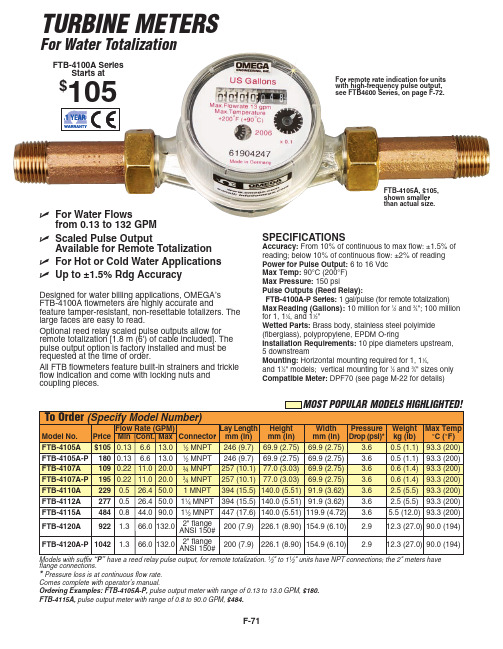
ߜ For Water Flows from 0.13 to 132 GPM
ߜ Scaled Pulse Output Available for Remote Totalization
ߜ For Hot or Cold Water Applications
ߜ Up to ±1.5% Rdg Accuracy
SPECIFICATIONS
Accuracy: From 10% of continuous to max flow: ±1.5% of reading; below 10% of continuous flow: ±2% of reading Power for Pulse Output: 6 to 16 Vdc Max Temp: 90°C (200°F) Max Pressure: 150 psi Pulse Outputs (Reed Relay): FTB-4100A-P Series: 1 gal/pulse (for remote totalization) Max Reading (Gallons): 10 million for 1⁄2 and 3⁄4"; 100 million for 1, 11⁄4, and 11⁄2" Wetted Parts: Brass body, stainless steel polyimide (fiberglass), polypropylene, EPDM O-ring Installation Requirements: 10 pipe diameters upstream, 5 downstream Mounting: Horizontal mounting required for 1, 11⁄4, and 11⁄2" models; vertical mounting for 1⁄2 and 3⁄4" sizes only Compatible Meter: DPF70 (see page M-22 for details)
Omega FTB3000系列流量计说明书

FTB3000 SeriesPositive Displacement Meters e-mail:**************For latest product manuals:Contents1.Introduction (3)2.Specifications (5)3.Operation (7)3.1Principle (7)3.2Precautions (7)4.Installation (9)5.Maintenance (11)5.1General (11)5.2Trouble Shooting (11)5.3Spare Parts (12)1.IntroductionThe FTB3000 Series of positive displacement meters incorporates smooth oval rotors in their design. The oval rotor principle has proven to be a reliable and highly accurate method of measuring flow. Along with the smooth oval rotors, exceptional repeatability and high accuracy over a wide range of viscosities and flow rates are features of the FTB3000 Series flow meter design.The low pressure drop and high pressure rating means the Omega FTB3000 Series flow meter is suitable for both gravity and pump (in line) applications.Please take a few minutes to read through this manual before installing and operating your meter. If you have any problems with the meter, refer to the maintenance and troubleshooting sections of this manual.If you need further assistance, contact Omega’s customer service department by telephone or fax for advice.2.SpecificationsService Fluids: Clean liquids, max particle size .125" Accuracy: ± 0.25% of reading or better above 100 cstk Repeatability:± 0.05%Flow Range:w/ Mag Coil Pickup 2 to 20 GPMw/ Hall Effect Pickup 0.02 to 20 GPMK-factor: 460 pulses per gallon (approximate)Operating Temperature:w/ Mag Coil Pickup: -268°C to +232°C (-450°F to +450°F)w/ Hall Effect Pickup: -40°C to +150°C (-40°F to +302°F)Operating Pressure: 3000 PSIG standardMinimum Fluid Viscosity: 100 cstkWetted Parts: 316 SS body and gears with peek gear seats Bearings: Shielded, self lubricating 440 SS ball bearings Connections:Flange Option: 1" MNPT STDPickup Coil: Magnetic Type or Hall Effect (6 to 24 vdc power) Calibration: 10-point calibration traceable to NIST @ 100 cstks3.Operation3.1PrincipleThe FTB3000 Series of positive displacement meters use a pair of smooth oval rotors to provide a reliable and highly accurate measurement of flow. The smooth oval rotors displace a precise volume of fluid which is passed through the measurement chamber during each revolution. The smooth oval rotor design along with the viscosity of the fluid provides a complete viscous seal within the measurement chamber.The unique patented design ofOmega’s Oval Gear meterincorporates two smooth ovalrotors 90 degrees out of phase.The phase relationship of therotors is maintained by twooval timing gears which areout of the flow path. The ovaltiming gears have a pitchdiameter equal to the outsidediameter of the smooth oval rotors.The flow through the meter measurement chamber follows the path of least resistance. Therefore no liquid passes through the center cavity between the rotors. The fluid is displaced from the inlet to the outlet via the area between the smooth oval rotors and the inner diameter of the meter housing.3.2Precautions▪Before use, confirm the fluid to be used is compatible with the meter and make certain that the operating conditions conform to the meter specifications.▪To prevent damage to the meter slowly fill the system with fluid (this will prevent damage that may be caused by air purge).▪Keep the flowrate within the meter ratings.▪Remove meter from the piping, replacing with a short pipe, when cleaning the piping system by flushing. Costly damage to the meter may result if the assembly is cleaned by flushing with the meter installed.4.Installation▪Use thread sealant on all pipe threads.▪Install the meter carefully to avoid pipe strains.▪The meter must be installed on the discharge side of the pump.▪In tank-head operation, the head of the fluid must be higher than the pressure loss of the meter.▪The flow direction must conform to the arrow mark on the meter body.▪The meter must be installed in the correct orientation (see figure below).▪Connect appropriate connector from pick-up from DCS or electronics.Pickup ConnectionsStandard MAGHall Effect(Open Collector) Redi-Pulse(Open Collector)A - Signal (+)B - Common (-)A - 8 - 30 Vdc (+)B - Common (-)C - Pulse OutputA - 3.5 - 24 Vdc (+)B - Common (-)C - Pulse Output5.Maintenance5.1GeneralThe Omega FTB3000 Series flowmeters do not require routine maintenance and do not contain any field serviceable or replaceableparts.5.2Trouble ShootingRefer to the following troubleshooting guide for assistance withpossible meter malfunctions:TROUBLE CAUSE REMEDYFluid will not flow through the meter ▪Meter installedwith incorrectorientation.Re-orientate the meter.▪Line to meterblocked.Clear line to meter.▪Insufficientdifferentialpressure.Increase upstreampressure.Reduced flow through the meter ▪Line to meterpartially blocked.Clear line to meter. ▪Insufficientdifferentialpressure.Increase upstreampressure.Meter readings inaccurate ▪Fluid flowrate istoo low.See “Specifications” formin and max flowrates. ▪Fluid viscosity toolow.Check fluidspecifications.▪Air in fluid. Bleed air from system. ▪Meter drag due toincorrectinstallation.Re-adjust meterinstallation.Meter not giving pulse signal ▪Faulty pickupsensor.Replace pickup sensor.Due to the precision alignment of the Omega FTB3000 Series flowmeter internals, field repairs are not recommended. Should the meter require internal repairs, return the meter to the factory.5.3Spare PartsThe following table contains the recommended spare parts for the Omega FTB3000 Series flowmeters:Item No. Qty Part No. Part Description1 1 300-6005 MAG Coil Pickup; PC24-45G1 1 300-6026 Intrinsically Safe MAGPickup; ISM-0011 1 300-6041 MAG Redi-Pulse Pickup;RPM01S1 1 300-6052 Hall Effect Pickup; HE01S NOTE:The meter pickup must be replaced with a pickup of the same type. Refer to the meter model number for the type of pickupbeing used.M3585/0411。
Omega FDH-1A Series 混合超声流量计说明书

HYBRID ULTRASONICFLOW METER Doppler or Transit Time in One UnitFDH-1A SeriesU S electableDoppler or Transit Time Operating Mode U Q uick and EasyClamp-On Transducer Installation U U ser Programmable Via 5-Button Menu Driven Interface U H igh Quality 320 x 240 Pixel QVGA Backlit LCD U D ata Logging toStandard SD Card Format U I solated 4 to 20 mA or 0 to 1 Khz PulseOutput (Fully Configurable)U O ptional Relays and CommunicationsDoppler technology is used to measure the flow rate of liquids with particulate and/or bubbles suspended in it. Transit timetechnology is used for clean liquids OMEGA’s FDH-1A Series hybrid ultrasonic flow meter allows customers to select betweendoppler and transit time technology with a single instrument. Isolated analog output, frequency output and the ability to data-log to standard SD cards are standard included features. The FDH-1A isprogrammed via a menu driven QVGA LCD display with a 5 button interface panel. Optional control functions with relay outputs are optional (-R3). The communications option package (-COMM) gives user’s RS232, RS485, USB andEthernet for interfacing to a PC.SPECIFICATIONSMeasuring Principle: Hybrid; user selectable doppler or transit time operating modes Fluid Types: Virtually any acoustically conductive fluid Transit Time Mode: 0 to 10% (0 to 100,000 ppm) particulate Doppler: 0.02 to 15% (200 to 150,000 ppm) 50 micron particles Fluid Velocity Range: 0.07 to 9.14 m (0.25 to 30') per second Flow Sensitivity: 0.0003 m (0.001') per second Nominal Pipe Sizes: 63 to 2500 mm (2.0 to 100")Enclosure: NEMA 4X (IP66), powder coated aluminum, SS clamps and hardware Dimensions: 279 H x 218 W x 127 mm D (11.00 x 8.60 x 5.00")Weight: 9.5 lb. (4.3 Kg)Mounting: Wall, pipe (vertical or horizontal) or panel mounting. Hardware included Panel Opening: 270 H x 206 W mm (10.63 x 8.10") Panel Depth Rear: 71 mm (2.78") Front: 55 mm (2.18")Power Requirements: 95 to 264 Vac50/60 Hz or 15 to 30 Vdc; 30 watts max Operating Temperature: -10 to 60ºC (14 to 140ºF) Storage: -40 to 70ºC (-40 to 158ºF)Display: 320 x 240 pixel QVGA backlit LCD, UV resistant. Simultaneous rate and Total; 10 digit max + exponent to E+32 decimal location configurable to 10 places Display Languages: English, Spanish, French or German selectable Keypad: Five-button positive action tactile switch keypad Security: Programmable master password and individual configuration passwords Display Volume Units: Independently configurable rate and total display units in U.S. Gallons, ounces, barrels (US liquid), barrels (US oil), cubic ft, acre ft, Imperial (British) gallons, liter, cubic meter, or user defined “custom” units. Rate display in feet or meters per second.Display Time Units: Seconds, minutes, hours, days Display/Output Response Time:Selectable; 0.25, 0.50, 1.0 (default), 2.5, 5.0 secondsFDH-1A, shownsmaller than actual size.Flow Rate Display Averaging:Selectable; 0.50, 1.0, 2.5, 5.0 (default), 10.0 secData Outputs: Isolated 4 to 20 mA output fully configurable, invertible; 0 to 1000 Hz pulse output fully configurable, invertibleData Logging: Date/time stamped flow rate and flow total data in FAT32 file format, easily imported into Excel. Configurable to trigger on time interval (1-999,999 sec), rate and/or total set-point values. Over 500,000 log events possible with included 32 MB SD card.Process Control (-R3 option): Three independently configurable 10 amp Form C, NO/NC relays.Configure to flow rate for high/low/ range rate alarm. Programmablerelease values enable auto release or manual latching operation.Configure to flow total for manual trigger batch operations or automatically triggered, timed batch operations.External Communications(-COMM Option): Computer connection via RS232, RS485, USB, Ethernet. Includes user communication and configuration software. Permits remote internet access through local network set-up. Remotely access and upload data logging files.Clamp-On TransducersHousing: NEMA 6P (IP67),Plastic: (PVDF base with Polypropylene cover), SS clamps and hardwareDimensions: 79 H x 75 W x 41 mm D (3.12 x 2.95 x 1.60")Weight (Excluding Cable): 0.8 lb (0.4 kg) eachCable: Shielded coaxial RG/U Type; 59. PVC jacket, black. RoHS Compliant Standard length: 3 m (10')Optional Lengths Available: 15 m (50'), 30 m (100')Pipe Surface Temperature: -34 to 121ºC (-20 to 250ºF)Shipping SpecificationsCarton Dimensions:533 H x 432 W x 241 mm D (21 x 17 x 9.5")Carton Weight: 24 lb (10.9 kg)before installing the transducers. The inside surface of the pipe must be smooth to properly reflect the sound wave.Note: For fluid, flow stream, minimum straight pipe and mounting requirements see the FDH-1A operator’s manual available online.Communications OptionsAny FDH-1A can be equipped with a communications package (-COMM) that includes Ethernet, USB, RS232, and RS485 connections, and proprietar user PC Software. When connected to a PC running the software, the user can access the configuration menu for program editing and data logging downloads directly into a PC.The software user interface mimics the 5-button touch pad so learning to use the software application is simple. Simply clicking on the buttons is the same as pressing the buttons on the FDH-1A touch pad. Pressing and holding shift while clicking on a button simulates pressing and holding a button on the touch padProcess Control OptionsAny FDH-1A model can be equipped with a process control relay package (-R3) that includes threeindependently programmable 10 A relays. Each relay can be configured to respond to changes in either the measured rate of flow or the accumulated total flow value. When assigned to monitor flow rate, high/low/range rate alarms are possible. When assigned to monitor accumulated total, manual trigger batch operations or automatically triggered, timed batch (proportional feed) operations are possible.(8.6)(5)(9.2)199(7.8)38(1.5)20(0.8) TYP.(0.75)33(1.30)(10.38)(2.5)264(10.4)75(2.95)Transducer (Series A)With Wall Mount HardwareComes complete with mounting hardware, stainless steel clamps, and operator’s manual.For units with 250V power and a CEE 7/VII plug add “-250VE” to the model number, no additional charge.For units with 250V power and a NEMA 6/15 plug add “-250V” to the model number, no additional charge.For units with 15.2 m (50') of sensor cable add “-50FT” to the model number for additional cost.For units with 30.5 m (100') of sensor cable add “-100FT” to the model number for additional cost.Ordering Examples: FDH-1A-50FT, hybrid doppler or transit time ultrasonic flow meter with 50' of transducer cable.FDH-1A-R3-250V, hybrid doppler of transit time ultrasonic flow meter with relay outputs, 250V power and NEMA 4X (IP66) electrical plug.。
OMEGA流量仪表产品说明书

Comes complete with operator’s manual. Other materials and lengths (up to 120") available. Consult OMEGA flow Engineering Department.For 230 Vac operation, add suffix “-230V” to model number, for additional cost. For 24 Vdc operation, add suffix “-24V” to model number, no additional cost. For 12 Vdc operation, add suffix “-12V” to model number, for additional cost.Ordering Examples: LVU-265S, 316 stainless steel, 2-wire, 4 to 20 mA output sensor,91.44 cm (36")�sensor immersion length. LVU-230S, 316 SS sensor with 10 A relay.K-34K LVU-230/260 Series U 1000:1 Wet-to-Dry Ratiowith 316 SS Machined Body SensorU E poxy Painted EnclosureU N o Calibration orSpecial Installation RequirementsU A C or 9 to 36 VdcPowered Models U Standard 3⁄4 NPT FittingsThe LVU-230 and LVU-260 liquid level switches are the ideal solution to a host of liquid-level sensing and control applications. Their small size and standard 3⁄4 NPT fittings make them suitable for new or existing applications. The LVU-230 models have a relay output along with a 316 SS or PVDF sensor and an integral miniaturized, encapsulated electronic control unit mounted in a cast aluminum, explosion-proof, watertight enclosure. The LVU-260 is a 2-wire, 4 or 20 mA output system.Both use an ultrasonic wave propagation sensor mounted in the liquid medium. The electronics generates a continuous wave ultrasonic signal that completely illuminates the liquid-sensing area. The absence of liquid in the sensing area causes the ultrasonic signal to dissipate, which the electronics senses as a “dry” condition (and provides a 4 mA output signal in the LVU-260). When liquid is present, the amplitude of the ultrasonic signal increases, indicating a “wet” condition. This signal is converted by the electronics and energizes the 10 A relay (LVU-230) or a 20 mA output signal (LVU-260). The LVU-230 electronics may be set to provide the control output to an alarm, pump, or other device on either a dry or wet condition.SPECIFICATIoNS Repeatability: 2 mm (0.08") typical Delay (on): 0.5 s Input Power: LVU-230: 115 Vac 50/60 Hz standard; 230 Vac 12 Vdc, or 24 Vdc (optional) LVU-260: 9 to 36 Vdc outputs: LVU-230: 10 A DPDT LVU-260: Low-level fail-safe: 4 ±1 mA dry; 20 ±1 mA wet; high level: 20 ±1 dry, 4 ±1 wet ¾ NPT THREAD Ultrasonic liqUid level switchesLVU-230S, shown smaller than actual size.Housing: NEMA 4/NEMA 7 watertight, explosion-proof enclosure, cast aluminum Class I, Group C and D, Class II, Groups E, F and G; and Class III, Division I and 2Sensor Material: L VU-230S, L VU-260S: 316 L SS L VU-230K, L VU-260K: PVDF Temperature: Sensor: -40 to 149°C (-40 to 300°F) Electronics: -29 to 77°C (-20 to 170°F)operating Pressure: Up to 1000 psig Mounting: 3⁄4 NPT standard Weight:453 g (1 lb)。
Omega FDP10 Series 电子流量计说明书

FDP10 Series Starts at
$414
ߜ Quick Response Time
ߜ Attitude Insensitive
ߜ Easy Maintenance
ߜ Bi-Directional Flow Passage
ߜ Volumetric Flow Measurement
This standard high-accuracy unit is supplied with an aluminum body flow block and 1⁄4" compression fittings. The upper case is molded of high-impact polycarbonate. Air flow from 50 ccm to 5 LPM can be accommodated with 50:1 turndown.
414
0 to 200 cc/min
FDP14-(**)-(*)
414
0 to 500 cc/min
FDP15-(**)-(*)
414
0 to 1 LPM
FDP16-(**)-(*)
414
0 to 2 LPM
FDP17-(**)-(*)
414
0 to 5 LPM
Comes complete with operator’s manual. Note: Not for use with flammable gases. (*) Replace asterisk in model number with regulated outlet pressure in psig. (**) Replace double asterisk in model number with one of the following gas codes: A = air; CO2 = carbon dioxide; N = nitrogen; AR = argon; O2 = oxygen (add $75 cleaning charge for oxygen service).
Omega 流量计产品说明书

FTB500 Series Low Flowrate MetersIt is the policy of OMEGA Engineering, Inc. to comply with all worldwide safety and EMC/EMI regulations that apply. OMEGA is constantly pursuing certification of its products to the European New Approach Directives. OMEGA will add the CE mark to every appropriate device upon certification.The information contained in this document is believed to be correct, but OMEGA accepts no liability for anyCONTENTS1. Introduction (2)2. Operation (3)2.1 Principle (3)2.2 Precautions (3)3. Installation (4)3.1 General Piping (4)3.2 Strainers/Filters (5)3.3 Installation Kits (5)4. Maintenance (6)4.1 General (6)4.2 Disassembly (6)4.3 Inspection & Repair (6)4.4 Assembly (8)4.5 Pickup Coil Testing (8)4.6 Trouble Shooting (10)4.7 Spare Parts (11)1IntroductionWe are proud that you have selected an Omega Low Flowrate Meter, the finest precision flow transducer on the market.The Omega FTB500 Series of Low Flowrate Meters are designed to meet the need for a high quality low flow measurement device for service in low to moderate viscosity clean liquids and for gas applications.The information in this manual is provided to assist in the proper installation, use, and maintenance of your instrument.Please take a few minutes to read through this manual before installing and operating your meter. If you have any problems with the meter, refer to the maintenance and troubleshooting sections of this manual.If you need further assistance, contact your local Omega Representative or contact the Omega customer service department by telephone, fax, or email for advice.2Operation2.1PrincipleThe Omega FTB500 Series of Low Flowrate Meters has been developed to meet the need for a low flow measurement device for use with low to moderate viscosity clean liquids and for gas measurement applications.The Omega FTB500 Series of Low Flowrate Meters is a family of low flow rate measurement devices whose design is based on a Pelton Wheel-like rotor. The measured fluid is directed tangentially through a velocity nozzle against the rotor causing it to spin. The pickup coil senses the spinning motion of the rotor through the housing and converts it into a pulsing electrical signal. Summation of the pulsing electrical signal relates directly to the total flow, while the frequency is related to the flow rate.2.2Precautions♦Do not drop the meter. Dropping the meter may result in damage to the meter housing and/or internals.♦Do not operate the meter at flowrates greater than the maximum flowrate marked on the meter. Operating atflowrates greater than the maximum flowrate may over-spin the meter. Over-spinning may result in damage tothe meter.CAUTION:Avoid over-spinning the meter. Over-spinning the meter may result in damage to the meter internals and lead to meterfailure.3 InstallationUpon receipt of the flowmeter carefully inspected it, checking for any indications of damage which may have occurred during shipment. Inspect all packing material carefully for parts or components which may have been packed with the shipment. Refer to the packing list/invoice for a detailed list of items included in the shipment.3.1 General PipingThe Omega FTB500 Series of Low Flowrate Meters is capable of sensing fluid flow in one direction only. The meter housing is marked by a flow direction arrow to indicate the direction of flow through the meter. The meter must be installed in the piping in the correct orientation to ensure the most accurate and reliable operation. Care should be taken in the proper selection of the mating fittings. Size, type of material, and pressure rating should be the same as the flowmeter supplied.When it is expected that flow will be intermittent, the meter should not be mounted at a low point in the piping system. Solids which settle or congeal in the meter may affect meter performance.In order to achieve optimum electrical signal output from the flowmeter, due consideration must be given to its isolation from ambient electrical interference such as nearby motors, trans-formers, and solenoids.A typical flowmeter installation is shown below:Blocking and Bypass valves should be installed if it is necessary to do preventive maintenance on the flowmeter without shutting down the flow system. The Bypass valve can be opened before the Blocking valves are closed allowing the flow to continue while removing the turbine flowmeter for service.BYPASS RUN METER RUNIMPORTANT: All flow lines should be purged prior to installing themeter. To prevent possible damage to the meter, install themeter ONLY in flow lines that are clean and free of debris.Upon initial start-up of the system a spool piece should be installed in place of the flowmeter so that purging of the system can be performed to remove all particle debris which could cause damage to the meter internals. In applications where meter flushing is required after meter service, care should be taken as to not over-spin the meter, as severe meter damage may occur.CAUTION:Avoid over-spinning the meter. Over-spinning the meter may result in damage to the meter internals and lead to meterfailure.3.2Strainers/FiltersThe Omega FTB500 Series of Low Flowrate Meters is designed for use in a clean fluid service. However, the service fluid may carry some particulate material which would need to be removed before reaching the flowmeter. Under these conditions a strainer/filter may be required to reduce the potential hazard of fouling or damage that may be caused by foreign matter.METER SIZE MESH SIZE PARTICLE SIZE(Maximum)¼" to ½"100 .00555/" to 1¼"70 .00881½" to 3"40 .015If a strainer/filter is required in the system, it should be located upstream of the flowmeter taking care that the proper minimum distance is kept between the strainer and flowmeter.3.3Installation KitsInstallation kits for the Omega FTB500 Series of Low Flowrate Meters consist of two lengths of appropriate tubing cut to a length appropriate for the upstream and downstream straight pipe run with appropriate end fittings.4Maintenance4.1GeneralPreventive maintenance for the Omega FTB500 Series of LowFlowrate Meters consists of a thorough general inspection.Remove the meter from the service line and take to a clean workarea. Use the following procedures and exploded component views to remove, inspect, and reinsert the flowmeter internals.4.2Disassembly1.Hold the meter securely using a vise. Meter orientationshould be such that the threaded plug is facing up. Useextreme care not to damage the meter housing or pipingconnections when placing in the vise.ing a large-blade screwdriver, turn the plugcounterclockwise to remove.3.To remove the shaft assembly, carefully thread a 10-32screw into the hole provided in insert. Thread the screwinto the insert until it bottoms out (finger tight only).4.Turn the housing over and slowly and carefully pull theshaft assembly and internals out of the housing. Takecare not to damage the shaft, rotor, and/or bearings.5.Remove and discard the gasket/seal.4.3Inspection & Repair1.Examine the flowmeter internals for signs of corrosionor fouling by foreign materials.2.Examine the shaft, rotor, and bearings for signs of wearand/or damage.3.If wear or damage is present, replace with new parts.NOTE: Clean all of the internals in an approved cleaning solution.Exploded View: C – Hard Carbon Bearing ModelsExploded View: BB - Ball Bearing ModelsRotorRotor4.4 Assembly1.Install any new parts.2.Guide the rotor and bearing assembly onto the shaft.Make sure the rotor is installed with the cup side of thePelton wheel facing the “IN” side of the housing.3.Place a new gasket on the insert. Always use a newgasket.4.Place the shaft assembly insert, gasket, and rotorassembly back into housing by inverting the housing tokeep gasket and rotor assembly in place.5.Install the threaded plug and tighten to 50 ft-lb.4.5Pickup Coil TestingTesting the MAG and MCP (RF) coils consists of measuring the resistance with an ohmmeter. Resistance measurements are to be made when there is no flow through the meter or with the coil removed from the meter housing.1.Measure the resistance between pin A and pin B. Theresistance should be approximately as listed in thefollowing table of some common coils.2.The resistance from any pin to the case should be greaterthan 1 Mohm.COIL DC RESISTANCE(Ohms)MC2PAHT 15.0 ±10%MCP3A 11.5 ±10%PC13-74G 1800 ±10%PC13-74S 1850 ±15%PC24-45G 1350 ±10%PC24-45S 1850 ±15%PC28-13G 120 ±20%PC28-14G 180 ±20%If either resistance measurement fails, replace the pickup coil. Firmly seat the new coil in the flowmeter and tighten the locking nut.4.6Trouble ShootingRefer to the following troubleshooting guide for assistance with possible meter malfunctions:TROUBLE CAUSE REMEDY Fluid will not flow ▪Meter clogged. Clear meter.through the meter ▪Line to meterblocked.Clear line to meter.Reduced flow through the meter ▪Meter partiallyclogged.Clear meter.▪Line to meterpartially blocked.Clear line to meter.Meter readings inaccurate ▪Fluid flowrate isnot within meterflow range.See “Specifications” formin and max flowrates. ▪Meter drag due toworn or damagedparts.Replace worn ordamaged parts.Meter not giving pulse ▪Faulty pickup coil. Replace pickup coil.signal ▪Meter internals notturning due toworn or damagedparts. Replace worn or damaged parts.4.7Spare PartsThe following table contains the suggested spare parts for the Omega FTB500 Series of Low Flowrate Meters:Item No. Qty Part Description1 1 PickupCoil1 1 Seal/GasketAssembly1 1 Rotor1 1 BearingsAssembly1 1 ShaftSpecific meter parts are dependent upon the meter size and model, always have the complete meter model number or serial number available when consulting the factory.WARRANTY/DISCLAIMEROMEGA ENGINEERING, INC. warrants this unit to be free of defects in materials and workmanship for a period of 13 months from date of purchase. OMEGA’s WARRANTY adds an additional one (1) month grace period to the normal one (1) year product warranty to cover handling and shipping time. This ensures that OMEGA’s customers receive maximum coverage on each product.If the unit malfunctions, it must be returned to the factory for evaluation. OMEGA’s Customer Service Department will issue an Authorized Return (AR) number immediately upon phone or written request. U pon examination by OMEGA, if the unit is found to be defective, it will be repaired or replaced at no charge. OMEGA’s WARRANTY does not apply to defects resulting from any action of the purchaser, including but not limited to mishandling, improper interfacing, operation outside of design limits, improper repair, or unauthorized modification.This WARRANTY is VOID if the unit shows evidence of having been tampered with or shows evidence of having been damaged as a result of excessive corrosion; or current, heat, moisture or vibration; improper specification; misapplication; misuse or other operating conditions outside of OMEGA’s control. Components in which wear is not warranted, include but are not limited to contact points, fuses, and triacs.OMEGA is pleased to offer suggestions on the use of its various products. However, OMEGA neither assumes responsibility for any omissions or errors nor assumes liability for any damages that result from the use of its products in accordance with information provided by OMEGA, either verbal or written. OMEGA warrants only that the parts manufactured by the company will be as specified and free of defects. OMEGA MAKES NO OTHER WARRANTIES OR REPRESENTATIONS OF ANY KIND W HATSOEVER, EXPRESSED OR IMPLIED, EXCEPT THAT OF TITLE, AND ALL IMPLIED W ARRANTIES INCLUDING ANY W ARRANTY OF MERCHANTABILITY AND FITNESS FOR A PARTICULAR PURPOSE ARE HEREBY DISCLAIMED. LIMITATION OF LIABILITY: The remedies of purchaser set forth herein are exclusive, and the total liability of OMEGA with respect to this order, whether based on contract, warranty,negligence, indemnification, strict liability or otherwise, shall not exceed the purchase price of the component upon which liability is based. In no event shall OMEGA be liable for consequential, incidental or special damages.CONDITIONS: Equipment sold by OMEGA is not intended to be used, nor shall it be used: (1)as a “Basic Component” under 10 CFR 21 (NRC), used in or with any nuclear installation or activity; or (2) in medical applications or used on humans. Should any Product(s) be used in or with any nuclear installation or activity, medical application, used on humans, or misused in any way, OMEGA assumes no responsibility as set forth in our basic WARRANTY/ DISCLAIMER language, and, additionally, purchaser will indemnify OMEGA and hold OMEGA harmless from any liability or damage whatsoever arising out of the use of the Product(s) in such a manner.RETURN REQUESTS/INQUIRIESDirect all warranty and repair requests/inquiries to the OMEGA Customer Service Department.BEFORE RETU RNING ANY PRODU CT(S) TO OMEGA, PU RCHASER MU ST OBTAIN AN AU THORIZED RETU RN (AR) NU MBER FROM OMEGA’S CU STOMER SERVICE DEPARTMENT (IN ORDER TO AVOID PROCESSING DELAYS). The assigned AR number should then be marked on the outside of the return package and on any correspondence.The purchaser is responsible for shipping charges, freight, insurance and proper packaging to prevent breakage in transit.FOR WARRANTY RETURNS, please havethe following information available BEFOREcontacting OMEGA:1.Purchase Order number under whichthe product was PURCHASED,2.Model and serial number of the productunder warranty, and3.Repair instructions and/or specificproblems relative to the product.FOR NON-WARRANTY REPAIRS,consult OMEGA for current repair charges. Have the following information available BEFORE contacting OMEGA:1. Purchase Order number to cover the COST of the repair,2.Model and serial number of theproduct, and 3.Repair instructions and/or specific problemsrelative to the product.OMEGA’s policy is to make running changes, not model changes, whenever an improvement is possible. This affords our customers the latest in technology and engineering.OMEGA is a registered trademark of OMEGA ENGINEERING, INC.© Copyright 2011 OMEGA ENGINEERING, INC. All rights reserved. This document may not be copied, photocopied,Where Do I Find Everything I Need for Process Measurement and Control?OMEGA…Of Course!Shop online at SMTEMPERATUREⅪߜThermocouple, RTD & Thermistor Probes, Connectors, Panels & AssembliesⅪߜWire: Thermocouple, RTD & ThermistorⅪߜCalibrators & Ice Point ReferencesⅪߜRecorders, Controllers & Process MonitorsⅪߜInfrared PyrometersPRESSURE, STRAIN AND FORCEⅪߜTransducers & Strain GagesⅪߜLoad Cells & Pressure GagesⅪߜDisplacement TransducersⅪߜInstrumentation & AccessoriesFLOW/LEVELⅪߜRotameters, Gas Mass Flowmeters & Flow ComputersⅪߜAir Velocity IndicatorsⅪߜTurbine/Paddlewheel SystemsⅪߜTotalizers & Batch ControllerspH/CONDUCTIVITYⅪߜpH Electrodes, Testers & AccessoriesⅪߜBenchtop/Laboratory MetersⅪߜControllers, Calibrators, Simulators & PumpsⅪߜIndustrial pH & Conductivity EquipmentDATA ACQUISITIONⅪߜData Acquisition & Engineering SoftwareⅪߜCommunications-Based Acquisition SystemsⅪߜPlug-in Cards for Apple, IBM & CompatiblesⅪߜData Logging SystemsⅪߜRecorders, Printers & PlottersHEATERSⅪߜHeating CableⅪߜCartridge & Strip HeatersⅪߜImmersion & Band HeatersⅪߜFlexible HeatersⅪߜLaboratory HeatersENVIRONMENTALMONITORING AND CONTROLⅪߜMetering & Control InstrumentationⅪߜRefractometersⅪߜPumps & TubingⅪߜAir, Soil & Water MonitorsⅪߜIndustrial Water & Wastewater Treatment。
美国omega欧米茄微流量流量计简介

F-86F微流量流量计FTB300系列数字式叶轮流量计是适合低流量应用的经济实惠之选。
它们采用了红外线光束技术。
提供的连接口有¹⁄₈ FNPT 、¹⁄₄ FNPT 和³⁄₈"外径的管接头。
从低至30 mL/min 到7000 mL/min ,共有6种流量范围可供选择。
不带显示屏的型号可提供5 Vdc 灌电流脉冲输出信号。
带显示屏的流量计配有6位数字LCD 显示屏,最多可有4个十进制数位显示流速和累加流量。
所有流量计都有集电极开路警报输出。
可供用户选择的标度因子包括:流量单位(加仑、升、盎司和毫升);时间单位(分钟、小时、天)。
用户还可以设定自定义单位。
设定值和累加流量存储在非易失性内存中。
也可以禁用累加流量复位功能。
标准配置的流量计带有透明的PVC 观察透镜;耐化学品腐蚀的PVDF 透镜作为选件提供。
外壳采用耐候性Valox TM PBT ,达到NEMA 4X (IP56)等级。
规格最大工作压力:PVC 透镜:9 bar (130 psig) @ 21°C (70°F)P VDF 透镜(“-PVDF”选件): 150 psig (10 bar) @ 21°C (70°F)液体最高温度:PVC 透镜、FNPT 接头:0 psi 时可达54°C (130°F)P VDF 透镜(“-PVDF”选件)、管接头:0 psi 时可达 93°C (200°F)精度:满量程的±6%工作电源:9 ~ 28 Vdc 传感器类型:红外线光束警报输出:集电极开路,最高30 Vdc 外壳:NEMA 4X (IP56)运输重量:0.45 kg (1 lb)材质壳体、叶轮、轴材质:PVDF连接处材质FNPT 连接:PVC 管接头:PVDF 可选观察透镜材质 透明型:PVC不透明、耐化学品腐蚀型:PVDF (可选)O 形圈密封:氟橡胶(可选EPDM 橡胶)泵的压合密封:PVC 仅传感器型号:5 Vdc 数字方波(三芯)输出:三芯屏蔽电缆, 1.8 m (6')FTB321D ,图片小于实际尺寸。
- 1、下载文档前请自行甄别文档内容的完整性,平台不提供额外的编辑、内容补充、找答案等附加服务。
- 2、"仅部分预览"的文档,不可在线预览部分如存在完整性等问题,可反馈申请退款(可完整预览的文档不适用该条件!)。
- 3、如文档侵犯您的权益,请联系客服反馈,我们会尽快为您处理(人工客服工作时间:9:00-18:30)。
适用于粘稠液体的容积式流量计
FPD1000B系列是椭圆齿轮流量计产品线中三种紧凑型流量计之一。
有铝质、316不锈钢或PPS(聚苯硫醚)壳体可供选择。
FPD1000B系列可处理各种液体粘度。
FPD1000B系列
U标配0 ~ 1000 cP粘度转子,1⁄4"不锈钢型号上可提供1,000,000 cP高粘度转子
U外形紧凑、结实耐用并且可在现场维修
U即便在测量粘稠液体时,也能保持极高精度
U流量计设计最大限度减少了磨损部件——延长了产品
寿命
U配备簧片开关和霍尔效应传感器组合
U可处理最大尺寸为0.127 mm
(0.005")的颗粒
U出厂校准
U 易于安装
U可选多种输出和显示选件
U流量计随付有测量精度证书规格
精度:读数的±1.0%
重复性:±0.03%
接头类型:NPT(内螺纹)
外形尺寸:65(长)x 50 mm(高)
(2.58 x 1.97")
传感器选项:簧片开关(两线制SPST常
开簧片开关,额定功率3瓦特,最大150
Vdc)和霍尔效应传感器(25 mA NPN集
电极开路)
霍尔效应传感器的电源
要求:4.5 ~ 24 Vdc
(4.6 ~ 9 mA)
FPD1002B,脉冲
输出,图片小于实
际尺寸。
FPD1000D-TX,远程4 ~ 20 mA
输出,带可编程显示屏(回路供
电),图片小于实际尺寸。
输出选项:脉冲输出(标配);可选
4 ~ 20 mA变送器(-A型号)
显示屏:6位
最大粘度:1000 cP(标配);为316不
锈钢和铝质型号可选1,000,000 cP高粘
度转子(-HV)
滤网尺寸:200目[可滤除最小0.127 mm
(0.005”)的颗粒]
安装方式:轴必须安装在水平面中。
F-77
F-78
F3
不建议将铝质型号用于水流量测量。
欲购全氟橡胶O 形圈,请将后缀“-K”添加到型号中(需付额外费用)。
欲购1,000,000 cP 高粘度转子选件,请将后缀“-HV”添加到型号中(需付额外费用)(仅为FPD1003B 、FPD1203B 和FPD1103B 系列提供-HV 选项)。
订购示例:FPD1102B ,PPS 流量计,量程为0.53 ~ 26.40 GPH 。
FPD1203B ,316不锈钢流量计,量程为4 ~ 132 GPH 。
耐扭电缆固定头:Hubble PG7电气连接:
1⁄2
-20 UNF-2B (母)电缆:Belden 9363电缆长度:6 m (20')
安装方式:墙壁、面板或管道安装 工作电源:
-TX 型号:两线,回路供电 -BAT 型号:9 Vdc 锂电池
配置:2种累加流量(1种累计、1种批量),流速(GAL 、LTR 、2种用户定义单位)
工作环境:-18 ~ 60°C (0 ~ 140°F)材质:
外壳:乙缩醛、无定型尼龙(仅显示装置)、硅树脂、聚酯 密封:氟橡胶 紧固件:不锈钢 电缆绝缘层:
PVC 运输重量:0.9 kg (2 lb)
外壳:NEMA 4X (IP66)防护等级
FPD1002B ,脉冲输出,
图片小于实际尺寸。
FPD1000D-TX,远程4 ~ 20 mA输出,带可编程显示屏(回路供电),
图片小于实际尺寸。