CAP1系列自动转换开关说明书
常熟双电源开关 CAP1

The ambient temperature is -5℃ ~+ 40℃ and the average value within 24 hours isn't above +35℃.
The elevation isn't above 2000m. The relative humidity of the air isn't above 50% at the max. temperature of + 40℃ , it may be higher at the lower temperature. For example, it can be up to 90% at 20℃. Dew on the switch due to temperature alteration should be removed. Pollution protection:grade 3. Installing category: Ⅲ. Be suitable in electromagnic environment A.
{ J:基本型
Basic Type
E:电子型
控制器类型:
Electronic Type
Z:智能型
Con troller Type Intelligent Type
ZT:智能可通信型
Intelligent and Communicative Type
1
正 常 工 作 条 件 NORMAL WORKING CONDITION
6
自动转换开关操作性能 Operation function of automatic tranfer switch
8
自动转换开关与短路保护电器配合参考表 The referrence table for cooperating between Automatic Trasfer Switch and fuse
施耐德CAP1自动转换开关电器安装使用说明书

CAP1自动转换开关电器安装使用说明书开关本体:打开包装,应有下列零部件Open the package, there are following partsCAP1 AUTOMATIC TRANSFER SWITCHING EQUIPMENT MOUNTING OPERATION MANUALBasic switchNote: the relevent outline diagrams of detailedspecifications are seen this pages of outline andmounting dimensions of the operation manual.1)J type controller of 2-pole product is internal type, without this accessory.2)There is accessory when E or Z type controller is selected.3)The busbars are optionally equipped, when selecting, there are accessories.4)There are fasteners specifications in bracket.5)xA/B: number is A for 3-pole product, B for 4-pole product.6)The number of screws, spring washers and flat washers for assemble screws is respectively counted.7)The number is counted according recommended number.请检查开关和附件各零部件是否完好,如有缺损请及时与本公司联系解决。
保险杠隔离自动转换开关100-1000普通电流说明书

Technical Data Effective: August 2007Page 1T able of Contents Page Introduction . . . . . . . . . . . . . . . . . . . .2 Switch Application Section . . . . . . . .2 Features, Benefits andAccessories . . . . . . . . . . . . . . .2-3 Description . . . . . . . . . . . . . . . . . . .3-4 Functional/OperationalCapabilities . . . . . . . . . . . . . . . . .5 Logic . . . . . . . . . . . . . . . . . . . . . . . . .6 Switch and Feature Selection . . . .7-9 Transfer Switch Dimensions . . . . . .10 Dimensions and Weights . . . . . . . .11 Combination Bypass Isolation and Automatic T ransfer Switches100-1000 AmperesProven switch designed to ensure reliable transfer from normal to auxiliary power sources - for rapid restoration of essential power in critical applications.IntroductionCombination Bypass Isolation and Automatic Transfer Switches are designed for applications where preventative maintenance,inspection and testing must be accomplished while maintaining continuity of power to the load.This is typically required in standby power situations that require safe maintenance of the system with minimal disruption of power. Combination BypassIsolation and Automatic Transfer Switches meet or exceed allindustry standards for endurance,reliability and performance.Cutler-Hammer Maintenance Bypass Isolation Transfer Switches meet or exceed allindustry standards for endurance,reliability, and performance. They are listed under CSA 22.2 No 178and UL1008 standards for transfer switches.Design Highlights •Overcurrent protection available •Simple test circuit •Designed to safelywithstand fault currents •Manufactured in an ISO 9002/14001 facility and designed in an ISO 9001 facility•Seismic qualified for UBC Zone 4Switch Application SectionTransfer switch equipment offers flexibility and versatility to the system designer and user.Cutler-Hammer Bypass Isolation Transfer Switches are offered in two basic designs, doublesided (USA and Canada) and single-sided configuration (Canada Only). A double-sided bypass isolation transfer switchcompletely isolates the transfer switch while providing the user the ability to bypass the load to only one source, either the utility source or the emergency source as specified when ordered. In accordance with CSA C282-00(Institutional and ResidentialBuilding Occupancy Group B and Group C) require as a minimum a single sided bypass on emergency supply.All Switches include the basic features necessary for normal operation as standard ( see next page). Cutler-Hammer also offers an extensive array of optional features and accessories that permits the user to customize a new transfer switch to match the application. The customization process is simple. Select theappropriate catalogue number for your application from the charts.Then choose any optional features or accessories needed to complete the project requirements.Technical DataEffective: August 2007Page 2Bypass Isolation Transfer Switches 100 - 1000 Amperes25kA 35kA 42kA 50kA 65kA 100kA 200kA 30 - 2002,3,4Any*Any*Any*Any*Any*Any*FDC,JDC,KDC 2252Any*Any*Any*Any*Any*Any*FDC,JDC,KDC 3002,3,4Any*Any*Any*Any*Any*Any*KDC 4002,3,4Any*Any*Any*Any*Any*Any*KDC 6002,3,4Any*Any*Any*Any*Any*Any*LDC 800 - 10002,3,4Any*Any*Any*Any*Any*Any*---(FDB/FD)+LFD 150kA FDC,JDC,KDC FCL***,LCL***200 - 3002,3,4Any*Any*Any*Any*Any*KDC,NB-TP**LCL***4002,3,4Any*Any*Any*Any*Any*------6002,3Any*Any*Any*Any*Any*NB-TP ---8002,3Any*Any*Any*Any*---NB-TP ---600 - 10004Any*Any*Any*Any*---------10002,3Any*Any*Any*Any*---------(FD/FDB)+LFD (FD/FDB)+LFD (FD/FDB)+LFD (FD/FDB)+LFD KDC KDC KDC LCL 200 - 3002,3,4Any*Any*Any*KDC KDC LCL ---4002,3,4Any*Any*Any*KDC KDC ------6002,3Any*Any*Any*LDC ---------6004Any*------------------800 - 10002,3,4Any*------------------*Any manufacturers' breaker ** with P12 limiter *** 150kA maximum 04/16/07Any*Any*Any*480Y/277 and48030 - 1502,3,4Any*Any*WWhen protected by an upstream, any manufacturers' breaker or Cutler-Hammer circuit breaker as shown, the transfer switch is rated for use on a circuit capable of delivering not more than the RMS Symmetrical amps at the voltage shown below.Maximum fault level available at upstream device (kA symmetrical)Upstream any manufacturers' breaker or Cutler-Hammer circuit breaker typeVoltageTransfer Switch Ampere Rating Number of PolesSwitched---600Y/347 and60030 - 150120/240 and 240, 208Y/1202,3,4Any*Any*Features,Benefits and accessoriesSuperior main Contact Structure The combination Bypass Isolation and Automatic transfer Switch meets or exceeds the standards set forth in UL 1008, UL489, CSA 22.2 No 178 and CSA 22.2 No 5.No other transfer switchmanufacturer has met the rigid testing requirements of this combination of pletely enclosed contactsprovide both safety and reliability.They also ensure the integrity of the contact assemblies and minimize the need for periodic maintenance of the contacts,reducing downtime and maintenance time.Long-Life DesignMain contacts employ developed DE-ION® arc quenchers andcontact arcing horns for extended in-service life and reduced pitting and burning of contact services.Simple,Reliable OperationThe automatic transfer switch is operated by a single,unidirectional gear motor transfermechanism that receives itspower from the source to which is being transferred. Bypass and Isolating Mechanisms aremanually operated by handles which ensure true quick-break,quick-make operation under full load conditions.Secure IsolationInterlocking of ATS main contacts ensure that both power sources cannot be simultaneouslyconnected to the load. Bypass switches are mechanicallyinterlocked to prevent paralleling of sources.Versatile ControlControl Logic Panel interconnects with Power Switching Panel via insulated keyed plug connectors to permit total isolation ofcontrols for routine maintenance.Engine Starting ContactProvides a 10 ampere, 30 Vdc contact closure to initiate engine starting upon failure of the Normal Power Source. Thisfeature, specifically designed for low current applications, is wired to red terminal blocks on the identification and maintenance.Full Phase ProtectionProvides phase failure protection on each phase of Normal Power Source. Should voltage drop below a pre-selected, fullyadjustable value on any phase, a signal is sent to initiate engine start.Time Delay Normal to Emergency Delays the retransfer from Emergency/Standby PowerSource to Normal Power Source to permit stabilization of the Normal Power source before retransfer is made. Timing is adjustable 0-30 minutes and begins when the Normal Power Source appears. If theEmergency/Standby PowerSource is immediate, overriding the time delay.Time Delay Engine Cooldown Permits the engine to continue to run unloaded after transfer to the Normal Power Source has been made. Timing is adjustable 0-30minutes and begins when retransfer is completed.Technical DataEffective: August 2007Page 3100kA 200kA---J, T 200AJ, T ---400A R J, T 400A J, T ---600A J, T R 600A L ---1200A L ---800A ---L 1600A800 - 10002,3,4---L 1600A---J, T 200AJ,T ---400A R J, T 400A J, T ---600A J, T R 600A L ---1200A L ---800A ---L 1600A6004---L 1600A800 - 10002,3,4---L 1600A04/10/07When protected by an upstream fuse type shown, the transfer switch is rated for use on a circuit capable of delivering not more than the RMS Symmetrical amps at the voltage shown below.VoltageTransfer Switch Ampere RatingNumber of PolesSwitchedUpstream Fuse Type Maximum fault level available at upstream deviceMax FuseAmperes (kA symmetrical)120/240 and 240, 208Y/12030 - 2252,3,44002,3,43002,3,46002,3,4480Y/277, 480, 600Y/347 and60030 - 1502,3,4200 - 3002,3,44002,3,46002,3Fully rated NeutralProvides a fully rated solid neutral for all 2 and 3 pole switches. All 4 pole switches are supplied with switched neutral contacts of identical construction and rating as the power poles and are mounted on the power contact shaft, integral to the completely enclose contact assemblies.Emergency/Standby Source MonitoringRelay monitor prevents transfer from the Normal Power Source to the Emergency/Standby Power Source until that source has attained 90% of nominal voltage and frequency. In addition, when the switch is in theEmergency/Standby position and that source falls outside the monitored parameters, a load retransfer is initiated to the Normal Power Source if it is present.Indicating LightsIndicate source availability, switch position, transfer switch isolation position, and bypass modes.Description:Switch Operation:Bypass to Normal (Utility power) Turn “ENGINE SELECTOR” switch to “OFF” positionPlace isolating handle mechanism in “OFF”positionPosition bypass switch interlocking plate for “NORMAL BYPASS” operationPlace “NORMAL BYPASS” switch to “ON” position Bypass to emergency (standbypower)Turn “ENGINE SELECTOR” switchto “RUN” positionPlace isolating handle mechanismin “OFF”positionPosition bypass switch interlockingplate for “EMERGENCY BYPASS”operationPlace “EMERGENCY BYPASS”switch to “ON” positionReturn to Normal OperationPlace appropriate bypass switchin “OFF”positionPlace isolating handle mechanismin the “ON”positionTurn “ENGINE”switch to “AUTO”positionBenefitsThe combination Bypass Isolationand Automatic Transfer Switcheliminates all of the complicateddrawout mechanisms required oncompetitive products for totalisolation of the transfer switch,and instead utilizes foolproofmechanical interlocking platecombined with a positive TotalIsolation Mechanism. The result isthe safest, easiest-to-operatebypass isolation switch availablein the marketplace today.When the transfer switch is in theIsolated position, complete testingof the ATS can be accomplishedvia a special insulated keyedconnector.This allows theoperator to completely test theentire operating sequence of theATS while maintaining power tothe connected load.The combination Bypass Isolationand Automatic Transfer Switchutilizes modified moulded caseswitches, designed specifically forhigh duty repetitive load transfer,as a means to bypass and totallyisolate the transfer switch. Thisdevice provides for a reliable ,rugged installation that canwithstand very high level shortcircuits. In addition, 100-600ampere units utilize Series CTechnology that offers a highestWithstand, Closing andInterrupting Rating available inthe marketplace today.Technical Data Effective: August 2007Page 4Bypass Isolation Transfer Switches100 - 1000 AmperesEffective: August 2007Page 5Figure 2: Double Sided Bypass Double Line Diagram (available in Canada & USA)Functional and Operational CapabilitiesOur overall design criteria is to provide a you with a Combination Bypass Isolation and Automatic transfer Switch that offers theutmost in flexibility, reliability and value. The long list of standards and codes below illustrates the versatility of our unit. Thecombination Bypass Isolation and Automatic Transfer Switch meets or exceeds many national and international standards. It is also designed and built in accordance with the following:CSA 22.2 No 178 and UL1008-Standard for Automatic Transfer Switches.CSA 22.2 No 5 and UL489 -Standard for Moulded Case Circuit Breakers and Moulded Case Switches.CSA C282-Emergency Electrical supply for building.ISO 9000-International Organization for Standards.ISO 4001-Manufacturing Facility.UBC -Uniform building code for Seismic Zone 4Basic Switch DesignCombination Bypass Isolation and automatic Transfer Switchesconsist of Normal Bypass Switch,Emergency Bypass Switch, aPositive Isolating Mechanism and an Automatic Transfer Switch. All subassemblies are testedindividually, and the complete assembly is subjected to full operational testing beforeshipment from Cutler-Hammer’s Transfer Switch manufacturing facility.Technical DataEffective: August 2007Page 6Double Sided Bypass Isolation Transfer Switch shownLogic ControllerEmergency Bypass SwitchNormal Bypass SwitchIsolating MechanismAutomatic Transfer SwitchLogicApplication VersatilityWhether the application calls for open or closed transition, manual or automatic operation, Cutler-Hammer has the right logic controller for the task. ATC300 and ATC600 Controller has set a new standard for transfer switch technology featuring:•Microprocessor- based logic •Digital LCD display•Field programmable set-points •Voltmeter and frequency meter •True rms voltage sensing •Mimic BUS/LED display •Delayed transition capability •Plant exerciserAutomatic T ransfer Open T ransitionAvailable with:•Time delayed neutral•Pre-transfer signal•Manual Re-transfer (ATC600only)•In Phase monitor (ATC600 only)•Delayed transition low voltage decay (ATC600 only)Ease of maintenanceKeyed quick disconnect plugs areprovided for easy and completeisolation of the control circuitry.Maintenance can be performed onthe logic independent from thepower sections and still allow theuser to manually transfer powerunder full load conditions.Technical DataEffective: August 2007Page 7Logic Disconnect PlugsEase of MaintenanceAutomatic Transfer Open TransitionMP1 ControllerKeyed quick-disconnect plugs are pro-vided for easy and complete isolationof the control circuitry.Maintenance can be performed onthe logic independent from the powersections and still allow the user tomanually transfer power under fullload conditions.Available with:Time delayed neutralPre-transfer signalPreferred Source SelectionManual Re-tansferTechnical DataEffective: August 2007Page 8Catalogue Number Selection Guide (Canada transfer switches only)1.Single Sided Bypass Isolation Transfer Switches come standard with emergency bypass. If normal bypass is required, please specify when ordering.2.In accordance with CSA C282-00, Institutional and residential building occupancy (Group B and Group C) require a minimum a Single SidedBypass on Emergency supply.Catalogue Number Selection Guide (USA transfer switches only)Technical DataEffective: August 2007Page 9Table 2: Switch and Feature SelectionATC300 ATC600 Std.Std. Std.Std.Std. Std. Std. Std. Std. Std. Std. Std. Std. Std. Std. O Std. Std. Std. O O O O O Std. Std. Std.Std.Std. Std. O O O O N/A O N/A O Std.Std.O O Std.Std.O O Std.Std.O O Std.Std.O O O O O O O O O O O O O O O O O O O O O O Std.Std.Std. Std. O O O O ATS FEATURE Description1Time Delay Normal to Emergency (TDNE)2Time Delay Engine Start (TDES) 3Time Delay Emergency to Normal (TDEN)4Time Delay Engine Cooldown (TDEC) 5H Source2 - Phase Reversal Sensing5J Source2 - All Phase Undervoltage/Underfrequency 5K Source2 - All Phase Overvoltage/Overfrequency5L Source2 - All Phase Voltage unbalance and phase loss S6B Test Operator (Controller Faceplate)Std. Std.6D 2-Position Selector Selector Switch (Test/Auto)Std. O 6H 4-Position Selector Switch (Test/Auto/Manual/Engine Start)O O 6J Keyed 4-Position Selector Switch (Test/Auto/Manual/Engine Start) OO 7A Time Delay Emergency Fail (TDEF) Adjustable 0 - 6 Seconds)S 8C Time Delay Bypass EN Pushbutton (Controller Faceplate) Std.Std. 8D Time Delay Bypass NE Pushbutton (Controller Faceplate) Std. Std. 9B Maintenance / Electrical Operator Isolator Selector SwitchO O 9D Keyed Maintenance / Electrical Operator Isolator Selector Switch O O 10B Preferred Source Selector - Utility to Utility or Utility to Generator N/A O 10D Preferred Source Selector - Generator to Generator N/A O 12C Source1 Connected (LED)S 12CC Source1 Connected (30mm Pilot Light) O O 12D Source2 Connected (LED)S 12DD Source2 Connected (30mm Pilot Light) O O 12G Source1 Available (LED)S 12GG Source1 Available (30mm Pilot Light) O O 12H Source2 Available (LED)S 12HH Source2 Available (30mm Pilot Light)O O 12L Source1 Device Tripped (Selectable with option 16 only) O O 12M Source2 Device Tripped (Selectable with option 16 only) O O 14A Source1 Connected Auxiliary Relay (2NO/2NC Form C)O O 14B Source2 Connected Auxiliary Relay (2NO/2NC Form C)O O 14C Source1 Available (4NO/4NC Form C)O O 14D Source2 Available (4NO/4NC Form C)O O 14E Source1 Available (1NO/1NC Form C)O O 14F Source2 Available (1NO/1NC Form C)O O 14G Source1 Available (2NO/2NC Form C)O O 14H Source2 Available (2NO/2NC Form C)O O 15A Source1 Connected (2NO/2NC Form C)Std.Std. 15B Source2 Connected (2NO/2NC Form C)Std. Std. 15C Source1 Connected (4NO/4NC Form C)O O 15D Source2 Connected (4NO/4NC Form C)OOTTechnical DataEffective: August 2007Page 10 Table 2: Switch and Feature SelectionTechnical DataEffective: August 2007Page 11Table 2: Switch and Feature SelectionO O OOREFER REFERN/A O N/A O N/A O N/A O N/A O N/A O N/A O N/A O N/A O N/A O N/A N/A N/A N/A N/A N/A N/A O N/A O O O O O OO REFER REFER REFER REFER O O O O O O OO REFER REFER REFER REFER REFER REFER REFER REFER REFER REFER REFER REFER REFER REFER REFER REFER REFERREFER41A 100W Space Heater (c/w:Thermostat)41C 400W Space Heater (c/w:Thermostat)42Seismic Zone 4Certified (CBC,IBC,UBC,BOCA)45A Load Sequencing Contacts (1)45B Load Sequencing Contacts (2)45C Load Sequencing Contacts (3)45D Load Sequencing Contacts (4)45E Load Sequencing Contacts (5)45F Load Sequencing Contacts (6)45G Load Sequencing Contacts (7)45H Load Sequencing Contacts (8)45I Load Sequencing Contacts (9)45J Load Sequencing Contacts (10)47C Closed Transition In-Phase with default to Load Voltage Decay 47D Closed Transition OnlyN 47E Closed Transition In-Phase with default to Time Delay Neutral N 48A Communications -IPONI ModuleN 48F Communications -MPONI Module (MODBUS)N 51D150kA -Clipper device Connected to Source 1O 51E180kA -Clipper device Connected to Source 1O 51F1100kA -Clipper device Connected to Source 1O 51G150kA -CHSP device Connected to Source 1(240/120Vac single phase Only)R 51H175kA -CHSP device Connected to Source 1(240/120Vac single phase Only)R 51J4Telephone/Modem/DSL (4Lines Total)O 51K4Cable TV/Satellite Cable/Cable Modem (2Lines Total)Lines Total)O 51M4A 12Vdc Generator Start Circuit Protection O 51M4B 24Vdc Generator Start Circuit ProtectionO51NA151na1.100KA Surge Device w/Advisor Source1R 51NN151nn1.100KA Surge Device w/NetVisor Source 1R 51NS151ns1.100KA Surge Device w/SuperVisor Source 1R 51NS151sn1.200KA Surge Device w/NetVisor Source 1R 51QA151qa1.160KA Surge Device w/Advisor Source1R 51QN151qn1.160KA Surge Device w/NetVisor Source 1R 51QS151qs1.160KA Surge Device w/SuperVisor Source 1R 51SA151sa1.200KA Surge Device w/Advisor Source1R 51SS151ss1.200KA Surge Device w/SuperVisor Source 1R Std.=Standard Option on ControllerO =Optional*=Customer selects required transfer mode of operation.REFER =Please refer to Eaton sales office or BidmanagerÆpricing tool.N/A =Feature "Not Available"with selected controller.Technical DataEffective: August 2007Page 12Transfer Switch Dimensions in Inches (mm)Technical Data Effective: August 2007Page 13M a x M a x S w i t c h C S A A m p s V o lt sF r a m e B y p a s s F r a m e A B C D E F GH I J 150480F F 21/53382.5/20952.4/615.3/1357.5/19125.5/64824.5/62330/96579.5/201918/457150600F F 21/53382.5/20952.4/615.3/1357.5/19125.5/64824.5/62330/96579.5/201918/457200240F F 21/53382.5/20952.4/615.3/1357.5/19125.5/64824.5/62330/96579.5/201918/457225*240F F 21/53382.5/20952.4/615.3/1357.5/19125.5/64824.5/62330/96579.5/201918/457300480K K 21/53382.5/20952.4/615.3/1357.5/19133.2/84324.5/62338/96579.5/201918/457300600K K 21/53382.5/20952.4/615.3/1357.5/19133.2/84324.5/62338/96579.5/201918/457400240K K 21/53382.5/20952.4/615.3/1357.5/19133.2/84324.5/62338/96579.5/201918/457400480L K 21/53382.5/20952.4/615.3/1357.5/19133.2/84324.5/62338/96579.5/201918/457400600L K 21/53382.5/20952.4/615.3/1357.5/19133.2/84324.5/62338/96579.5/201918/457600240L L 21/53382.5/20952.4/615.3/1357.5/19133.2/84324.5/62338/96579.5/201918/457600480M L 21/53382.5/20952.4/615.3/1357.5/19133.2/84324.5/62338/96579.5/201918/457600600M L 21/53382.5/20952.4/615.3/1357.5/19133.2/84324.5/62338/96579.5/201918/457800240N B M D 27.12/68994.5/23252.4/615.3/13513.5/34333.2/84330.5/77538/96591.5/232424/610800480N B M D 27.12/68994.5/23252.4/615.3/13513.5/34333.2/84330.5/77538/96591.5/232424/610800600N B M D 27.12/68994.5/23252.4/615.3/13513.5/34333.2/84330.5/77538/96591.5/232424/6101000240N B N D 27.12/68994.5/23252.4/615.3/13513.5/34333.2/84330.5/77538/96591.5/232424/6101000480N B N D 27.12/68994.5/23252.4/615.3/13513.5/34333.2/84330.5/77538/96591.5/232424/6101000600N B N D 27.12/68994.5/23252.4/615.3/13513.5/34333.2/84330.5/77538/96591.5/232424/610M a x M a x S w i t c h C S A A m p sV o l t s F r a m e B y p a s s F r a m eA B C D E F GHIJ150480F F 21/53382.5/20952.4/615.3/1357.5/19125.5/64824.5/62330/96579.5/201918/457150600F F 21/53382.5/20952.4/615.3/1357.5/19125.5/64824.5/62330/96579.5/201918/457200240F F 21/53382.5/20952.4/615.3/1357.5/19125.5/64824.5/62330/96579.5/201918/457300480K K 21/53382.5/20952.4/615.3/1357.5/19133.2/84324.5/62338/96579.5/201918/457300600K K 21/53382.5/20952.4/615.3/1357.5/19133.2/84324.5/62338/96579.5/201918/457400240K K 21/53382.5/20952.4/615.3/1357.5/19133.2/84324.5/62338/96579.5/201918/457400480L K 21/53382.5/20952.4/615.3/1357.5/19133.2/84324.5/62338/96579.5/201918/457400600L K 21/53382.5/20952.4/615.3/1357.5/19133.2/84324.5/62338/96579.5/201918/457600240L L 21/53382.5/20952.4/615.3/1357.5/19143.2/109724.5/62348/121979.5/201918/457600480N B N D 27.12/68994.5/23252.4/615.3/13513.5/34343.2/109730.5/77548/121991.5/232424/610600600N B N D 27.12/68994.5/23252.4/615.3/13513.5/34343.2/109730.5/77548/121991.5/232424/610800240N B N D 27.12/68994.5/23252.4/615.3/13513.5/34343.2/109730.5/77548/121991.5/232424/610800480N B N D 27.12/68994.5/23252.4/615.3/13513.5/34343.2/109730.5/77548/121991.5/232424/610800600N B N D 27.12/68994.5/23252.4/615.3/13513.5/34343.2/109730.5/77548/121991.5/232424/6101000240N B N D 27.12/68994.5/23252.4/615.3/13513.5/34343.2/109730.5/77548/121991.5/232424/6101000480N B N D 27.12/68994.5/23252.4/615.3/13513.5/34343.2/109730.5/77548/121991.5/232424/6101000600N B N D 27.12/68994.5/23252.4/615.3/13513.5/34343.2/109730.5/77548/121991.5/232424/610*S i n g l e P h a s e O n l yB Y P A S S I S O L A T I O N A T S (4P O L E )D I M E N S I O N S (I NC H E S /M M )B Y P A S S I S O L A T I O N A T S (2&3P O L E )D I ME N S I O N S (I N C H E S /M M )Technical DataEffective: August 2007Page 14C S A C 22.2S p e c 178C e r t i f i e d A T S。
单相电力调整器PAC01A说明书

选型表单相调压器负载电源220VAC 恒阻负载电流80A 加热器断线报警,无特殊调功★负载电源和同步电压:调压工作方式时,负载电源和同步电压必须同相位.一. PAC01A主要技术指标:1.4~20mA输入: 接收阻抗500Ω~1.5K;调压分辨力: 0.1% 。
2.负载电源: 50Hz 单相110VAC/220VAC/380VAC 移相范围:0~170°3. 同步电源:110VAC/220VAC/380VAC,见标牌4. 外部电压调整: 10K带刻度盘电位器调整范围 0~100% 。
5.缓启、缓停: 起停开关控制缓启动、缓停时间均固定为15秒。
无起停开关控制时,第一次上电自动缓启动。
6.80℃超温保护:散热器温度大于80℃±3℃禁止输出并报警解除:故障排除后,重新上电。
7.电流容量: 40A 、 60A 、 80A 、 120A 、150A AC8. 报警输出: 光电隔离OC门输出,隔离电压1500V (5~24VDC的外供电源)。
二.三. 安装及使用须知:● 使用前请认真阅读本说明书,严格按要求接线使用。
● 本电压调整器需垂直安装在通风良好,不受日光直射或热辐射,无腐蚀性无可燃性的环境中。
● 工作电流 >30A,需采用强制风冷。
高温高湿以及海拔大于1000米,应降额使用。
● 装置过热保护后,如要再运行,需排除故障后,再送电运行。
● 工作环境温度:-10℃~+55℃ 通风良好的位置。
工作环境相对湿度: 90%。
● 负载短路保护:一般按额定负载电流的1.5倍选择,外配RS0快速熔断器作为短路保护。
● 感性负载必须使用外部起停开关和加热器断线报警HB 功能(选件) 四. 初步调试1. 初始接线:参照最简接线图接线,为调试可靠,一般先接100~200W 灯泡假负载并将仪表置手动状态。
手动电压输出范围为0~100%。
此时,负载电压应均匀变化。
仪表无手动,输入20mA ,可利用外部电压调整电位器重复试验。
ca1系列自动转换开关技术参数表-ca1系列自动转换开关主要性能、控制

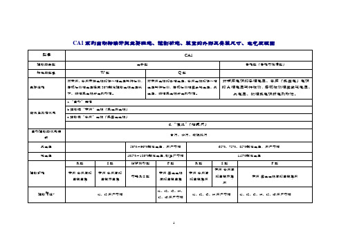
CA1系列自动转换开关主要性能、控制功能、装置的外形及安装尺寸、电气原理图∙CA1系列自动转换开关控制器R型、S型、F型三种控制功能简介∙电网-电网间的自投自复(R型)R型的控制器对两路电源(分别称为常用电源和备用电源)进行自动切换。
正常状态时应由常用电源供电,当常用电源出现异常(被检测相电压发生过压、欠压、缺相或电源断电)时,经已设定的延时时间自动切换至备用电源供电;当常用电源恢复正常后,经已设定的延时时间自动返回至常用电源供电。
注:Q1合及Q1分表示控制常用电源的断路器合闸或分闸;Q2合及Q2分表示控制备用电源的断路器合闸或分闸。
∙电网-电网间的自投不自复(S型)自投不自复的控制器对两路电源(分别称为常用电源和备用电源)进行自动切换。
在常用电源出现异常(被检测相电压发生过压、欠压、缺相或电源断电)时,经已设定的延时自动切换至备用电源,但当常用电源恢复正常后,不能自动回复。
只有当备用电源出现异常才进行切换。
注:Q1合及Q1分表示控制常用电源的断路器合闸或分闸;Q2合及Q2分表示控制备用电源的断路器合闸或分闸。
∙电网-发电电源间的自投自复(F型)F型控制器对两路电源(分别为电网电源和发电电源)进行自动切换。
在电网电源出现异常(被检测相电压发生过压、欠压、缺相或电源断电)时,控制器经发电指令延时发出发电指令请求发电。
当发电电源电压至50%~90%额定电压(对Q型转换器)或70%额定控制电源电压(对W型转接器),装置从电网断开负载电路,自动切换到发电电源。
当电网电压恢复正常后,则又自动返回到电网供电,并发出停止发电指令。
注:Q1合及Q1分表示控制电网电源的断路器合闸或分闸;Q2合及Q2分表示控制备用电源的断路器合闸或分闸。
CA1自动转换开关主要规格及执行断路器选用。
LMR PLUS电力火栓控制器与自动转换开关1-1说明书
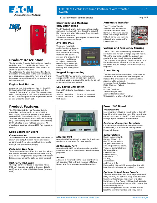
The Automatic Transfer Switch Option may be added to any FD type Fire Pump Controller whenever automatic transfer from normal to alternate power is required.The automatic Transfer Switch and Fire Pump Controller are mounted in the same enclosure or in separate enclosures to form one unit and interwired - depending on the horsepower and voltage required.Product DescriptionProduct Features Engine Test Button Logic Controller BoardPower I/O BoardElectrically and Mechani-cally InterlockedATC-300 PlusAutomatic TransferVoltage and Frequency SensingAlarm RelayKeypad ProgrammingLED Status IndicationAn engine test button is provided on the ATC-300 controller that can be used to test the Source 2 (generator) engine. The operator can select the engine run test time (0-600 minutes). As well, a silence pushbutton is provided which de-energizes the alarm bell.The FT Series transfer switch operating mecha-nisms are mechanically interlocked to preventthe normal and alternate source from connect-ing at the same time.The switch operates upon signals received fromthe ATC-300 Plus controller.The panel mounted,multi-function, micropro-cessor based ATC-300Plus controller accuratelymonitors two powersources and provides thenecessary intelligenceto reliably operate thetransfer switch througha series of programmedsensing and timing func-tions.The ATC-300 Plus controller membrane isequipped with seven keypad input buttonswhich are used to program the controller as wellas set operating parameters.Five LED’s indicate the status of the powersources.Source 1 Available Source 1 ConnectedSource 2 Available Source 2 ConnectedUnit StatusThe FT Series TransferSwitches will perform anautomatic transfer fromNormal to Alternate sourcewhen the Voltage drops to85% of normal, or there isa loss of any phase and/orPhase Reversal.The ATC-300 Plus continuously monitors thenormal source for out of range setpoint values.When the source is outside the dropout set-points, the source will become unavailable.This prompts a transfer to the alternate source.Retransfer occurs when the normal source’sfrequency and/or voltage return within pickupsetpoints.The alarm relay is de-energized to indicate anabsence of an alarm state and energized toindicate the presence of an alarm condition.Alarm conditions include:Improper Circuit Breaker OperationMotor Operator FailureLockoutFailsafe ConditionAborted Engine TestAborted Plant ExerciserUnsuccessful in-phase TransitionThe FT20 Limited Service Transfer Switch Controller can be used for motors 30HP or less, driving special fire service pumps where acceptable to the authority having jurisdiction. They are available with across-the-line starting only, with starting inrush current approximately 600% of rated motor full load amperes. All models are supplied with an LMR Plus micropro-cessor.CommunicationThe controller can be ordered with the option to display and output current values and status, on command, from various software protocols through the appropriate port(s).Embedded Web PageThe web page is a multifunction tool that allows the user to view the controller’s current status, data values, programmed set points and history. It is accessed using the optional ethernet port.USB Port / USB DriveThe logic controller board is equipped with a USB port that can be used to transfer data to and from a portable USB Drive device (memory stick).Ethernet PortAn optional ethernet port is used for direct con-nection to a computer for data transfer.RS485 Serial PortAn optional RS485 serial port can be providedfor communication to various external softwareprograms.BuzzerA buzzer is mounted on the logic board whichwill operate if Fail to Start, Hardware Malfunc-tion or any Common Alarm condition exists.TransformersIncoming line voltage is run directly to the I/Oboard from the incoming lines. The three trans-formers mounted on the I/O board will acceptvoltage inputs between 100 and 600V.Customer Connection TerminalsConnection terminals for external customerconnections, are located on the top of thePower I/O board.Output RelaysSeven socket mount,8 Amp, 2 Form - C(DPDT) output relaysare provided standardon each power I/O board.They are designated for:Common Alarm,Phase Failure,Phase Reversal,Pump Run,Startup,Accelerationand Future # 1.Each socket has an LED mounted on the I/Oboard which indicates each relay’s coil status.Optional Output Relay BoardsT here is provision to add up to eight additionalrelay outputs, via optional relay output boards.Each board contains a maximum of 2 addi-tional relays. The Power I/O Board will accept amaximum of 4 optional boards which mount in asnap-on configuration.Each board provides an area for the user tolabel the terminal number and relay name.Door MountThe membrane keypad is accessible from the front door of the controller.NEMA RatingThe standard membrane keypad is rated for NEMA 2, 3R, 4, 4X and 12.LCD DisplayThe Logic Control Board contains a 4 Line by 40 Characters wide, backlit, LCD display which is capable of generating multiple languages.Alarm & Status LED’sA total of 20, ( 10 Status - 10 Alarm ) LED’sprovide indication on the membrane keypad.Power OnPump RunningLocal StartRemote StartDeluge Valve Emergency Start Interlock OnLow PressureAuto Shutdown Enabled Programmable LED # 1Phase Reversal Phase FailureFail To Start Undervoltage OvervoltageLow Room Temperature Locked Rotor TripLow Suction Pressure Source 2 Disconnected Programmable LED # 2Status LED’s Alarm LED’sSilence ButtonA silence pushbutton on the membrane canbe used to silence the buzzer. When an alarm condition exists, the alarm buzzer will sound. If the Silence Alarm button is pressed, the alarm buzzer will turn off. If a subsequent alarm con-dition occurs after the silence button is pressed, the buzzer will re-sound. Pressing the Silence Alarm button again, will silence the buzzer. Motor Test ButtonThe motor test button on the membrane can be used to simulate an automatic start. Automatic Shutdown EnabledWhen the Automatic Shutdown function is en-abled, a Green LED will indicate on the control-ler membrane.MAIN DISPLAYGeneralThe main display will show the current systempressure, time and date, voltage and ampsreading for all three phases, the system fre-quency and any custom messages, alarms ortimers.Programmed Set-PointThe set-point display will show programmedpressure start point, pressure stop point andweekly test timer setting.StatisticsThe statistics display will allow the user to scrollthrough all of the measured statistics stored inmemory. Refer to LMR Plus operation manualIM05805020K for specific details.DiagnosticsThe diagnostics display will allow the user toscroll thorough eleven diagnostic points to assistwith troubleshooting the system.Message HistoryThe user will be able to scroll through all ofthe messages stored in the memory of thecontroller with the most recent message beingdisplayed first.PRINT MenuDescriptionAll fault and alarm information is sent to theUSB and Printer ports on demand, as well asthe status of each output. The LMR Plus willstore up to 10K events which are time and datestamped. All information can also be retrievedand displayed on the LCD display.Saving to USB DriveThe controller will save four separate text files,one CSV file and the embedded webpage to theUSB external drive. The files, at maximum size,can be saved multiple times on one 128MB USBdrive.Files to be saved are: Status Report, DiagnosticsReport, Statistics Report, Configuration File andLast 10K Messages.Print MenuThe printer menu is accessed in order to selectthe desired print function.Functions include: Print Messages, Last XX Mes-sages, Date & Time, Status Report, DiagnosticsReport and Statistics Report.Custom MessagesWhen this item is selected, custom messagescan be cleared from memory or downloadedfrom the USB external drive.Firmware UpdateFirmware revisions are updated from an ex-ternal USB drive. All previously programmedsettings will remain intact when updating iscompleted. Should there be an update failure,the controller will automatically revert back tothe previous version of firmware.Embedded WebpageGeneralThe embedded webpage is a multifunction toolthat will allow the user to view the current sta-tus of the controller as well as display all currentreadings, set points, and history. An externalcomputer can be connected via the optional Eth-ernet port to access the page. When connected,the controller set points can be programmed viathe webpage.Multiple PagesThere are 5 viewable pages that show the MainDisplay, Statistics, Diagnostics, History andProgrammed Set Points.Pressure PointsThe pressure reports recorded in memory canbe graphed and/or sorted based on date andtime.Programmed Set PointsAll of the programmed set points and their cur-rent status can be viewed via the webpage.Custom MessagesUsers can create custom messages on acomputer and upload to the controller using aUSB Drive (memory stick). Up to 10 custommessages of up to 100 characters each, willcontinuously scroll across the fourth line of theLCD display once uploaded.Trigger PointsThe message can be programmed to appear atspecific trigger points such as specific date andtime, specific number of operations, specificnumber of hours run or at any individual alarmpoint.All of the trigger points can be selected as And/Or values.The LMR Plus Electric Fire Pump Controllers meet or exceed the requirements of Under-writers Laboratories, Underwriters Laboratories Canada, the Canadian Standards Asso-ciation, New York City building code, CE mark and U.B.C / C.B.C. Seismic requirements, and are built to NFPA 20 standards.Standards & CertificationProduct FeaturesProgramming Menu GeneralThe LMR Plus programming menu isdivided into 8 different sub-menus. Each sub-menu contains information relative to it’s particular function. A brief description of each sub-menu is listed below.LanguageThe language sub-menu allows the user to select English, French or Spanish or Other languages to be viewed on the LCD Display. Several other languages can be uploaded into the controller . Contact the factory for details.RegionalRegional settings include the ability to program the date by adjusting the Month, Day, Year and Day of Week. As well, the Current Time can be adjusted on the 24 hour clock.PressureA variety of pressure settings can be programmed in the pressure sub-menu. These settings include disabling thepressure transducer; setting of the start point, stop point, low pressure alarm, high pressure alarm, stop mode, proof pres-sure switch (for foam units), low suction shutdown (low foam shutdown), pressure deviation and hourly pressure recording. Refer to the LMR Plus operation manual IM05805020K for details.TimersTimers in the LMR Plus that can beprogrammed include: Run Period Timer (RPT), RPT Start Mode, Acceleration Timer (AT), Weekly Test Timer , Fail to Start Timer (FST) and Sequential Start Timer (SST). Refer to the LMR Plus operation manual IM05805020K for details.Alarm Set PointsThere are five settable alarm points that can be programmed by the user . They in-clude: Phase Rotation, Over Voltage (OV), Under Voltage (UV), Over Frequency (OF) and Under Frequency (UF). Refer to the LMR Plus operation manual IM05805020K for details.Custom Inputs / OutputsThere is provision on the Power I/O Board to accept up to 9 additional inputs and 9 additional outputs. The inputs can be labeled using one of 11 pre-set inputdescriptions or assigned a custom descrip-tion that is programmed by the user . The optional outputs can be programmed to indicate up to 25 output conditions. As well, two optional alarm LED’s can be pro-grammed for up to 12 alarm conditions.All optional inputs, outputs and LED’s can be linked, as required.Inputs can be programmed to energize the common alarm output, link to relays and optional LED’s and latch until reset by the user . Outputs can be programmed for fail safe and latch until reset by the user . Optional inputs and outputs can be programmed with time delay B External Drive GeneralWhen using an external USB Drive, the drive should conform to the following minimum specifications:Min: 128mb Max: 2 Gig FAT16 protocol USB 1.0 or 2.0Drain Valve SolenoidAll LMR Plus electric controllers areequipped with a drain valve solenoid used for weekly test purposes.NEMA 2 EnclosuresAll LMR Plus controllers come standard with NEMA 2 enclosures unless otherwise ordered. Available options include: NEMA 3R, 4, 4X, 12.Emergency Start OperatorA mechanically operated emergency start handle activates the motor contactor inde-pendent of any electrical control circuits orpressure switch input.。
ca1系列自动转换开关技术参数表-ca1系列自动转换开关主要性能、控制
CA1系列自动转换开关主要性能、控制功能、装置的外形及安装尺寸、电气原理图∙CA1系列自动转换开关控制器R型、S型、F型三种控制功能简介∙电网-电网间的自投自复(R型)R型的控制器对两路电源(分别称为常用电源和备用电源)进行自动切换。
正常状态时应由常用电源供电,当常用电源出现异常(被检测相电压发生过压、欠压、缺相或电源断电)时,经已设定的延时时间自动切换至备用电源供电;当常用电源恢复正常后,经已设定的延时时间自动返回至常用电源供电。
R型控制器的功能见下表:注:Q1合及Q1分表示控制常用电源的断路器合闸或分闸;Q2合及Q2分表示控制备用电源的断路器合闸或分闸。
∙电网-电网间的自投不自复(S型)自投不自复的控制器对两路电源(分别称为常用电源和备用电源)进行自动切换。
在常用电源出现异常(被检测相电压发生过压、欠压、缺相或电源断电)时,经已设定的延时自动切换至备用电源,但当常用电源恢复正常后,不能自动回复。
只有当备用电源出现异常才进行切换。
S型控制器的功能见下表::Q1合及Q1分表示控制常用电源的断路器合闸或分闸;Q2合及Q2分表示控制备用电源的断路器合闸或分闸。
电网-发电电源间的自投自复(F型)F型控制器对两路电源(分别为电网电源和发电电源)进行自动切换。
在电网电源出现异常(被检测相电压发生过压、欠压、缺相或电源断电)时,控制器经发电指令延时发出发电指令请求发电。
当发电电源电压至50%~90%额定电压(对Q型转换器)或70%额定控制电源电压(对W型转接器),装置从电网断开负载电路,自动切换到发电电源。
当电网电压恢复正常后,则又自动返回到电网供电,并发出停止发电指令。
Q1合及Q1分表示控制电网电源的断路器合闸或分闸;Q2合及Q2分表示控制备用电源的断路器合闸或分闸。
R型、S型、F型自动控制器控制特性:CA1自动转换开关主要规格及执行断路器选用。
ABB CAP 501 保护设备参数设置工具说明书
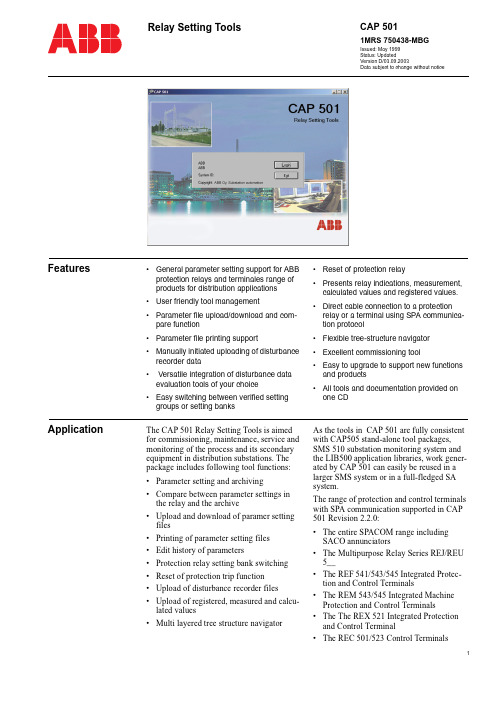
11MRS 750438-MBGIssued: May 1999Status: UpdatedVersion D/03.09.2003Data subject to change without noticeCAP 501Relay Setting ToolsFeatures•General parameter setting support for ABB protection relays and terminales range of products for distribution applications •User friendly tool management•Parameter file upload/download and com-pare function •Parameter file printing support•Manually initiated uploading of disturbance recorder data • Versatile integration of disturbance data evaluation tools of your choice •Easy switching between verified setting groups or setting banks•Reset of protection relay•Presents relay indications, measurement, calculated values and registered values.•Direct cable connection to a protection relay or a terminal using SPA communica-tion protocol •Flexible tree-structure navigator •Excellent commissioning tool•Easy to upgrade to support new functions and products •All tools and documentation provided on one CDApplicationThe CAP 501 Relay Setting Tools is aimed for commissioning, maintenance, service and monitoring of the process and its secondary equipment in distribution substations. The package includes following tool functions:•Parameter setting and archiving •Compare between parameter settings in the relay and the archive •Upload and download of paramer setting files •Printing of parameter setting files •Edit history of parameters•Protection relay setting bank switching •Reset of protection trip function •Upload of disturbance recorder files •Upload of registered, measured and calcu-lated values •Multi layered tree structure navigatorAs the tools in CAP 501 are fully consistent with CAP505 stand-alone tool packages, SMS 510 substation monitoring system and the LIB500 application libraries, work gener-ated by CAP 501 can easily be reused in a larger SMS system or in a full-fledged SA system.The range of protection and control terminals with SPA communication supported in CAP 501 Revision 2.2.0:•The entire SPACOM range including SACO annunciators•The Multipurpose Relay Series REJ/REU 5__•The REF 541/543/545 Integrated Protec-tion and Control Terminals•The REM 543/545 Integrated Machine Protection and Control Terminals•The The REX 521 Integrated Protection and Control Terminal•The REC 501/523 Control Terminals2Further information about CAP 501 and its application in single relay applications and in local and remote system solutions can be found in the full product documentation on the product CD-ROM.Design The CAP 501 product consists of a base sys-tem with a navigator on which support toolsfor the protection and control terminals arerunCategorization of the software parts Base SystemKernel software, navigator, communicationconfiguration, additional base tools and ser-vices are providing a framework for theobject types and tools.Fig. 1CAP 501 Navigation windowRelay setting toolIncluding all functions belonging to parame-ter, register- and input values and reset func-tions. The package include one tool forSPACOM products and one tool for all otherterminals.Fig. 2Relay setting tool REMMIDisturbance recorder toolIncludes the functionality to upload and pre-sent disturbance recordings..Fig. 3Recorder tool windowFig. 4DR tool windowSystem configurationThe tool package is delivered on a CD whichcan be installed on a PC with Win NT or Win2000 operating system.The PC communicates to the protection relayor terminal using the SPA protocol via a prod-uct specific cable connected between the PC,sCOM port and the communication interfaceof the relay. The communication is alwayspoint to point.Document files CAP 501 documentation in PDF format andan installer for installing the Acrobat Readerfrom Adobe Corporation are included on theCD. The Acrobat Reader is needed to viewthe documentationTechnical data CAP 501 v.2.2.0 sets the following hardwareand software requirements for the PC:Software requirementsHardware requirementsOrdering The following alternatives are available:•CAP 501 version v.2.2.0. tool packageCD-ROM is delivered free of charge witha protection relay or terminal whenrequested. •If ordered separately, an order handling fee will be charged.Ordering number: 1MRS151019Operating system Microsoft Windows NT 4.0 Workstation.It is recommended to have Service Pack 5 installed.Microsoft Windows 2000 .It is recommended to have Service Pack 3 installed.Network Operating system network software installed with at least one networkprotocol (e.g. TCP/IP)Item Minimum RecommendedProcessor 233 MHz or higher Pentiumcompatible CPU 1 GHz or higher Pentium compatible CPUMemory128 MB256 MBDisplay SVGA, 800x600, 256 colours SVGA, 1024x768, 256 colours File system NTFS file system on theinstallation driveHard disk space300 MB500 MBCD-ROM drive Any device supported by theoperating system. Required forinstallationMouse Any device supported by theoperating systemPCI slots One slot for each PCLTA-20 cardPCMCIA slots One slot for each PCC-10 cardNetwork adapter card Any device supported by theoperating systemTRADEMARKS.Intel and Pentium are registered trademarks of Intel Corporation.Neuron, LON and L ON W ORKS are registered trademarks of Echelon CorporationAcrobat is a registered trademark of Adobe Systems Incorporated.All Microsoft products referenced in this document are either trademarks or registered trademarks of Microsoft Corpo-ration.Other brand or product names are trademarks or registered trademarks of their respective holders.3ABB OySubstation Automation P.O. Box 699FIN-65101 Vaasa, Finland Tel +3581022 11Fax +358102241094/substationautomationThe communication cables listed in the next table are not included in the CAP 501 delivery. Required communication cables can be acquired by placing a separate order, see the table below:Table 1: Communication harwareRelayTypeOrder numberREF 541, 543, 545REM 54_REC REX A-series Opto1MCK950001-1REM 610Opto (Please contact your nearest ABB representative for availability.)1MRS050698SPTO front connector SPCR front connector RS 232 - RS 232SPA-ZP 17A3SPACOM 100/300 series RS 232 - TTL connector SPA-ZP 5A3SPAC 300/500/600 series rear RS 232 - RS 485SPA-ZP 6A2SACO 16A3, 16D1, 16D3 and 64D4Connection cable for SPA-ZP 6A2 to SACO srew terminalsSPA-ZP 21A and SPA-ZP 6A2。