天然气汽车操作及维护手册
车用燃气CNG汽车保养作业指导书

车用燃气CNG汽车保养作业指导书
天然气汽车各级保养周期及作业内容:
1、按照汽车《使用说明书》和国家相关规定对汽车进行定期维护保养。
2、汽车每行驶3000km,维护保养内容;清洁空滤器、混合器皮膜;检查燃气装置、高低压管线、管接头、阀是否有漏气和损坏,安装是否可靠,高低压管线是否和其他部件磨蹭,橡胶软管是否损坏、老化;汽油管及接头是否渗漏。
3、每行驶7500km 维护保养内容;拆高压过滤器,用高压气体对滤芯进行反冲;检查燃气装置系统各部分是否渗漏;更换损坏的()形图;检查一级减压器输出压力是否正常,减压器安全卸压阀工作是否正常,三级调压器输出压力是否正常;
4、汽车每行驶15000km 维护保养内容;更换天然气过滤器芯,检修减压调节器,更换一级减压器上的滤芯;检修混合器,检修各种气阀;清洁发动机冷却第,检查循环水胶管有损坏和老化现象;发动机排气管,消声器是否松动、漏气和燃气管线、阀的隔热装置是否可靠;
5、汽车每行驶25000km维护和保养内容:检查二级三角膜片,二级杠杆是否磨损,必要时更换。
解体情洗化
油器,松果浮子室、加速泵等部件的工作性能;
6、汽车每行驶50000km维护保养内容;检查二级内盖及三级杠杆、钻孔是否磨损,必要时更换;
7、每次维护时,检查钢瓶的完好、坚固情况,支架、螺栓是否牢固可靠,如发现钢支架不符合安全使用条件,必须及时更换和检修。
压缩天然气钢瓶使用1-2年后应由专业部门检定。
天然气汽车驾驶员操作规程

一、充装天然气的要求:(1)充气时严格执行加气站安全制度、充气安全操作规程。
挂上排档和拉上手刹车,关闭车上所有电气装置(包括收音机、CD等)断开电源。
充气时系统及气瓶内压力不得超过额定工作压力(CNG不大于20Mpa;LPG不大于2.2Mpa)。
警告:严禁违反安全操作规程!!!(2)充气后,应注意检查系统接口是否有漏气现象,若发现漏气和其他异常故障,先关气瓶阀断掉气源、再排出或烧尽余气,使用汽油到改装厂排除故障及隐患。
要求:每辆燃气车配试漏瓶。
(3)打开瓶口阀时,人不得站在瓶口阀的正面,截止阀应缓慢开启,防止冲击压力表、阀和其他零件。
要求:每辆燃气车驾驶员掌握气瓶截止阀的开、关及正确使用。
二、出车前例检:检查燃气系统高压表指示压力,和停车前比较有无明显的下降,燃气储存情况,装置和管线是否有漏气现象,各部件,管线有无松动及异常情况,如有松动漏气及时排除。
三、发动机起动操作要求:1、用汽油起动打开点火钥匙到发动机运行档,打开转换开关至用油档,数秒后,将点火钥匙转到起动档,即可用汽油起动行驶。
2、用燃气起动(1)化油器车:由于化油器中有汽油,这时压缩天然气不易发动,需将化油器中汽油用完后,方可用天燃气起动,首先,将转换开关至空档,起动发动机,当发动机内汽油即将用完时,迅速将转换开关至用气档,即可用燃气运行。
或将转换开关至空档,起动发动机将化油器中的汽油用完,发动机停止运转后,将转换开关至用气档,重新起动发动机,用天然气运行。
(2)电喷车:将转换开关至自动切换档,按汽油车正常起动,转速超过设定值即可用压缩天然气运行。
3、用燃气作燃料起步,应以起步档位起步;起步前应切换至气态,发动机水温应在40℃以上,否则会造成发动机磨损和减压器因冰堵冻裂的不良后果。
警告:燃气的车辆必须使用防冻液。
四、行驶中的要求:(1)用燃气运行时,发动机水温应保持在60℃—90℃为宜,水温过低易造成一级减压器冰堵或蒸发减压器工作不正常,至使空挡滑行熄火、有严重安全隐患!燃气耗气量上升。
天然气汽车使用及保养
天然气汽车使用及保养摘要:随着我国经济的不断发展,交通状况越来越复杂,如何降低汽车排放对环境的影响,保护环境已成为全社会亟待解决的重大问题。
天然气汽车以其环保、经济、安全等优势应运而生,并得到了广泛的推广和普及。
本文将从车辆的使用和保养两方面进行探讨,旨在为广大用户提供有关天然气汽车的使用和保养知识,以确保其安全、经济、环保出行。
关键词:天然气汽车、使用、保养正文:一、天然气汽车的优势天然气汽车的使用优势非常明显:(1)环保:使用天然气汽车可以减少大气污染排放,具有更好的环境保护效果。
(2)经济:天然气汽车燃料成本较低,更加经济实用。
(3)安全:由于天然气本身是一种非常安全的燃料,在使用过程中很少发生火灾、爆炸等事故。
(4)可靠性:天然气发动机具有更高的功率和更长的使用寿命。
(5)推广政策优惠:我国政府长期以来推出了一系列天然气汽车相关的政策优惠,从购车到使用都可以享受政策优惠。
二、天然气汽车的使用(1)加气:使用天然气汽车,加气是一个必不可少的步骤。
用户可以通过加气站将天然气注入汽车油箱中。
在使用天然气汽车时,需要注意加气时的气压、气温和容器的安全性。
(2)行驶:天然气汽车同其他汽车一样需要经过不同路况和环境的考验。
用户需要注意的是,在驾驶天然气汽车的过程中,应保证车辆高度稳定、速度平稳。
(3)维护保养:天然气汽车需要定期检查、维护和保养,以确保汽车长时间、安全地运行。
用户应该关注天然气汽车的油耗、机油、冷却液等等。
三、天然气汽车的保养(1)日常保养:天然气汽车需要进行日常保养,包括车身清洗、保养、检查刹车、机油更换,如有发现问题应及时处理。
(2)定期保养:定期保养主要包括更换滤清器、更换曲轴箱油和其他油品、检查和清洗发动机冷却系统、检查电池和交流发电机等等。
定期保养不仅可以保证汽车的性能,同时延长汽车的使用寿命。
(3)如何保养:对于天然气汽车的保养,用户可以根据自己的车型以及车辆使用状况进行保养。
天然气燃气汽车操作规程

燃气汽车使用操作规程汽油-天然气两用燃料汽车是一种新型动力汽车。
CNG燃料以安全、环保、经济的特点用作城市公交动力具有十分重要的意义。
驾驶员应掌握汽油-天然气两用燃料汽车的特点,了解CNG作燃料时的燃烧特性及动力性能,熟悉掌握两用燃料汽车气路的布局、布置与重要部件的作用及性能,为正确操纵汽车奠定良好的基础,现就有关内容要求如下:一、、新购车辆置换规定及燃气调整工艺(一)、新购车辆燃气置换规定1、新购车初次加天然气前,必须进行低(7Mpa)、高压(20Mpa)二级空气检漏,确保各瓶阀、仪表、管路、减压阀等器件连接无漏气,卡套紧固。
2、在空气检漏完毕后,充入2Mpa氮气,置换瓶与管路中的空气,贮存氮气排出,至氧气含量低于3%,置换达标方可将贮存氮气排出,压力降至0.2Mpa时,充入天然气。
3、充入天然气时,必须关闭主供气阀,并检查充气管路、单向阀、过流保护阀、瓶阀是否漏气;若漏气,必须停止充气,关闭瓶阀,打开充气阀排出管路气。
除瓶阀外,其它可重新安装排除。
瓶阀漏气时,必须拆瓶送生产厂(北京天海钢瓶生产厂)校验。
排除全部充气网络漏气,可使天然气车载气瓶充至2Mpa 压力。
然后将汽车驶离加气站至空旷通风地带,用天然气置换氮气。
贮气瓶排气,当压力降至0.2Mp时,关闭充气阀。
重新加天然气至20Mpa。
充气完毕,关闭全部气瓶阀,安装好加气口防尘塞,关闭车身侧门,驶离加气站。
4、加完天然气的车辆驶入维修沟上,紧固气瓶支架螺栓,消除气瓶松动震颤;排出汽油箱、汽油滤清器汽油泵、化油器及汽油管中的燃油,摘下电油泵电源线并进行绝缘处理;调校气门间隙至发动机装配标准的上限,调整火花塞间隙在0.7-0.9mm。
紧固气缸盖螺栓至标准扭矩。
5、在无气压状态拆开减压器进气管并移置旁边,打开主供气阀进行5秒钟吹管后关闭主供气阀,安装减压器进气管,并检验是否漏气。
6、将油气转换开关调至“气”档,打开钥匙门,起动发动机,调整怠速混合气浓度,再调整点火时间,最后调整主供气功率阀,发动机转速达到额定转速止为调整完毕。
天然气车辆使用保养说明书(精装版)
目录目录 (1)第一部分 CNG天然气供气部分 (1)一、CNG车辆供气系统简介 (1)二、CNG车辆供气系统操作规范 (3)三、CNG车辆的使用和保养 (4)四、CNG车辆燃气部分基本故障与排除 (6)第二部分 LNG天然气供气部分 (7)一、LNG车辆供气系统简介 (7)二、LNG车辆供气系统操作规范 (9)三、LNG车辆的维护和保养 (11)四、LNG车辆燃气部分基本故障与排除 (11)第一部分 CNG 天然气供气部分一、CNG 车辆供气系统简介1.天然气汽车燃气供给系统原理图1 天然气汽车燃气管路供给系统原理图2. CNG 供给系统组成、技术参数及使用要求天然气车供气系统主要由气瓶、管路、集成控制面板、高压过滤器、高压电磁阀、高压减压器、低压过滤器、低压电磁阀等组成。
注:气瓶应定期到相关部门检查、管路定期检查是否漏气。
2.1集成控制面板功能:集成控制面板是将充气截止阀、总截止阀、气瓶压力表、充气口集中在一块面板上,将充气、切断等功能进行集成。
图2 CNG 集成控制面板充气口总截止阀充气截止阀气瓶压力表2.1.1充气口功能:实现快速安全充装天然气。
(内置单向阀防止气体泄漏,当单向阀的橡胶圈老化或者损坏时,使用专用工具更换,以免损坏充气阀体。
)2.1.2总截止阀功能:手动截断气瓶与发动机间的气体流动。
当车辆停放时间较长或是长时间不用时,应关闭此阀,以切断气瓶向发动机提供燃料的通道。
“Close”为关, “Open”为开。
2.1.3充气截止阀功能:手动截断充气口与气瓶间的气体流动。
当气瓶充气时打开此阀,充气完毕时关闭此阀。
“Close”为关, “Open”为开。
切记:为防止总截止阀与充气截止阀损坏,需轻开轻关。
2.1.4气瓶压力表功用:用于显示气瓶内的压力。
2.2高压滤清器2.2.1功用:过滤气体中的水和油等杂质,以保气路的畅通。
2.2.2相关技术参数额定工作压力:20 MPa过滤精度:0.3-0.6um环境温度:-40-120℃2.3高压电磁阀2.3.1功能:停机时自动切断发动机的供气通路。
康诺流体 HPNGV2 系列压缩天然气车用调压器使用说明书和维护手册

Enidine / Conoflow105 Commerce Way Westminster, SC 29693Tel: (864) 647-9521 Fax: (864) 647-9574INSTRUCTION AND MAINTENANCE MANUALHPNGV2 Series Compressed Natural GasVehicle RegulatorWARNING: These instructions must be read carefully prior to installation and system startup.INTRODUCTION: The HPNGV Series regulator is a self contained, pressure reducing regulator designed and qualified for 3000 and 3600 psig CNG vehicular fuel systems. This regulator is factory calibrated and is not field adjustable. Various configurations of this regulator are available, based on the application needs. Consult the factory for part numbers, service kits, or configuration assistance.SYSTEM REQUIREMENTS : High pressure CNGfiltration (1 micron rating) is required to keep particulates in the gas stream from damaging the regulator and downstream components. The filter must be located upstream of the pressure regulator. Clean, burr free fittings and lines must be used to prevent particulate damage to the regulator.CONNECTIONS : The HPNGV Series regulator is connected to the fuel system by inlet and outlet ports. These ports use CNG compliant SAE J1926 o-ring boss connections for 3/8” size tubing at the inlet connection (9/16-18 thread) and 1/2” size tubing at the outlet connection (3/4-16 thread). These connections are labeled “INLET” and “OUTLET”. The inlet and outlet lines must be sized for sufficient flow, and the outlet fitting must provide a 3/8” minimum bore for gas flow.A coolant circulation bowl is provided which permits engine heat to warm the regulator and prevent internal icing of the regulator valve. An optional coolantcirculation bowl is available with a thermostat. Both coolant bowls are labeled for coolant inlet and outlet, adjacent to the connections. Standard coolant lineconnections are for 3/8” reinforced rubber hose, which is secured with hose clamps.An optional SAE-3 transducer port is available to allow a high pressure transducer to be directly installed in the regulator to measure inlet pressure.Optional pressure bias controls (manifold pressure reference) are available.A pressure relief device (PRD) is provided. Standard (light duty) configurations discharge directly to atmosphere, while capture pipes are available for enclosed spaces or heavy duty applications.CAUTION: The regulator’s PRD is a control and nota system safety device. It may not protect theregulator or fuel system under all possible / potential failure modes. A downstream safety valve or other failsafe strategy must be used to fully protect the fuel system and vehicle. The PRD port must not be blocked by any obstruction.MOUNTING : Two (2) M8 X 1.25 threaded holes areprovided in the regulator to enable sturdy mounting. The regulator may be oriented in any direction; however Conoflow recommends that the gas ports arehorizontally oriented to minimize exposure of the gas lines, and prevent collection of oil and moisture in the downstream line. The regulator must be rigidly mounted on the vehicle, and protected from impact of road debris.WARNING : Do not mount the regulator by gas or coolant connections only. This regulator must be securely mounted by M8 x 1.25 bolts.Please refer to the interface drawings for mounting dimensions, connection identification and connection details.SPECIFICATIONS:Maximum Operating Inlet Pressure:3600 psig (248 bar)Outlet Pressure: Factory preset – see regulator labelWARNINGConoflow’s products are designed andmanufactured using materials and workmanship required to meet applicable standards. The use of these products should be confined to services specified and/or recommended in the Conoflow catalogs, instructions, or by Conoflow application engineers.To avoid personal injury or equipment damage resulting from misuse or misapplication of a product, it is necessary to select the proper materials of construction and pressure-temperature ratings which are consistent with performance requirements.Outlet Pressure Variation in Service: -10 to +18 psi from labeled setting throughout the range of operating inlet pressure, temperature and gas flow. See flow performance graph to see effect of changes to inlet pressure and gas flow.Temperature Range: -40° F to 250° F(-40 °C to 120 °C) Connection Torques: Inlet (SAE-6): 27 ft-lbOutlet (SAE-8): 42 ft-lbTransducer (SAE-3): 8 ft-lbMounting Bolts: 15 ft-lbFlow Capacity: To 175 lb/hr of CNG. (Flowvaries by application, consultthe factory for data.)PRD Opening: 200 +/- 40 psig (optional)270 +/- 60 psig (standard)350 +/- 60 psig (optional)PRD Type: ReseatableMATERIALS OF CONSTRUCTION:Body: 6061-T6 AluminumBonnet: 6061-T6 Aluminum Diaphragm / Seals: Nitrile Rubber classValve Trim: Stainless Steel / Polyimide /PEEKNOTE: This regulator has been tested and certified for safe and reliable service in Natural Gas Vehicles. There are significant potential hazards associated with CNG which the user and / or installer must be aware of when using this product.CAUTION: Install the regulator in accordance with NFPA 52, CAN/CGA-B149.4 and other codes and standards applicable to the jurisdiction of installation and service.WARNING: CNG can cause damage and / or injury due to very high pressure, flammability, and extreme cold during expansion. Suitable safeguards must be employed during installation, commissioning and service to prevent harm to personnel and property.PRINCIPLE OF OPERATIONThe HPNGV series is a mechanical pressure regulator. The main valve, within the regulator, is coupled to a diaphragm assembly. A spring preload against the diaphragm assembly pushes the main valve open. As gas flows through the regulator, downstream pressure will increase and push the diaphragm assembly against the spring load, closing the main valve. The diaphragm and valve are dynamic, and will seek equilibrium so the inlet pressure is reduced and regulated throughout the useful range of gas flow.When the engine is shut off, gas flow through the regulator ceases. The regulator’s main valve is pulled closed by the diaphragm assembly and downstream pressure will be trapped in the low pressure side of the fuel system.An engine coolant circulation bowl is fitted over the end of the regulator to provide engine heat to the regulator valve and the gas. This heat prevents ice buildup in the regulator, which could reduce performance and regulator life.INSTALLATION GUIDELINES1. Plan the installation for the best combination ofaccessibility, protection from engine exhaustheat, mechanical vibration or impact, andsuitable mounting orientation.SEE SYSTEM IMPERATIVES ON PAGES 3 and 42. A suitable lubricant (oil, synthetic grease, etc)should be applied to the o-ring of the fitting, priorto installation, to help the o-ring seat and seal.Do not use silicon grease – silicon may poisonthe oxygen sensor in some vehicles. Install thefitting in the applicable gas port.3. If the regulator is equipped with an optional PRDcapture pipe, connect the system fitting to thecapture pipe.NOTE: If the optional ¼” NPT PRD CapturePipe is used, it must be wrench supportedduring connection.4. Attach regulator securely to vehicle, using twoM8 x 1.25 mounting bolts (not included).5. Connect the inlet, outlet, and coolantconnections. Assure any entrapped air inregulator is fully purged from coolant bowl. Ifapplicable, connect the PRD and transducer.6. Pressurize the system and perform a leak test ofgas connections with liquid leak detectionsolution or soapy water.SYSTEM IMPERATIVESImperatives are those conditions, when violated, can cause regulator or system failure and an increased risk of gas release. The following imperatives are listed with potential risks to assist the fuel system integrator with system design failure modes and effects analysis.1. Upstream Coalescing FilterAlthough the regulator is equipped with an internal filter, a suitable coalescing filter must be installed immediately upstream of the regulator. This filter should be sized for suitable flow and condensate capacity. The purpose of this filter is to prevent excessive moisture and compressor oil or particulate contaminants from entering the regulator and flowing downstream to the fuel management system.A one (1) micron filter will sufficiently protect the regulator from particulate contamination damage.This filter must be located as close to the regulator as possible to prevent any particulate in the connection between the filter and regulator from accelerating upon system pressurization, and piercing the regulator’s internal filter.2. Upstream Lockoff (solenoid) ValveA normally closed solenoid valve must be installed upstream of the regulator. This is a safety requirement to prevent gas from freely flowing during vehicle shutdown. Although the regulator is capable of bubble tight shutoff, the upstream lockoff valve is the correct safety device for this function.3. SealantsSealants are not required for the SAE o-ring boss connections. The use of sealants as a fitting leakage preventive measure can contaminate the internal passages and valve in the regulator and cause a malfunction. Sealant use in these connections will void the factory warranty.4. Inlet / Outlet LinesTo prevent excessive pressure drop at flow, the inlet and outlet fuel lines should be of suitable size. The regulator has been designed for SAE o-ring boss fittings which correspond to 3/8 inch OD tubing (SAE-6) for the inlet, and 1/2 inch OD tubing (SAE-8) for the outlet. These are the recommended line sizes. Excessively large line or fitting diameters may induce instability of the delivery pressure. The minimum bore of the fittings must be a minimum of 0.27 inch (6.8 mm) for the SAE-6 inlet fitting and 0.37 inch (9.4 mm) for the SAE-8 outlet fitting. Fittings may be of type SAE J1926/2 or SAE J1926/3.Tubing must be clean and free of burrs, which could contaminate the regulator or system. The outlet line should not be run upward from the regulator outlet port, due to the potential for excessive oil and condensate collection. A level or downward run is preferred to prevent collection.5. Downstream Relief ValveAlthough the regulator is equipped with a pressure relief device (PRD), a high flow relief valve or other protective strategy must be installed between the regulator outlet and the remainder of the fuel system. The regulator PRD is not a high flow device and may not protect the regulator or fuel system in case of sudden failure.6. Engine CoolantThe expansion of high pressure gas to low pressure creates a significant temperature drop. To prevent moisture from freezing inside the regulator and creating a blockage, heated engine coolant must be circulated within the regulator. The regulator is equipped with a coolant bowl for this purpose.Engine coolant must be maintained for at least –40 degree antifreeze protection. If the coolant were to freeze in the regulator, for any reason, the coolant containment integrity may be compromised.Suggested minimum flow: Engine idle 1-2 lpm, Moderate power 3-6 lpm, depending on engine size.7. Excessive TemperatureThe regulator is designed for safe and reliable operation within a temperature range of –40 to 250 °F. Temperatures beyond 275 °F can cause permanent damage to internal seals and must be avoided. If the regulator is located in an area with the potential for high temperature (such as radiated energy from exhaust system components, etc), suitable heat shields must be employed.8. Fitting TorqueThe correct assembly torque for the inlet (SAE-6) fitting is 27 ft-lb.The correct assembly torque for the outlet (SAE-8) fitting is 42 ft-lb.The correct assembly torque for the optional transducer port is 8 ft-lb.Inadequate torque could allow the fitting to loosen in service and leak. Excessive torque could weaken or shear the threads in the inlet and / or outlet port of the regulator.The inlet and outlet fitting is sealed with an o-ring.9. Submergence in waterExcept for bonnet bias models, the regulator uses an atmospheric reference hole in the bonnet to sense ambient pressure. This hole is “filled” with a porous hydrophobic plastic plug to prevent water intrusion from splashing, wash down, etc. This plug may not prevent water intrusion if the regulator were to be submerged in water. For this reason, the regulator should not be mounted low in a vehicle which would have to cross flooded roads, etc.10. Chemicals in FuelAny cleaners or abnormal additives, drying agents, etc in the fuel could cause damage to the regulator’s internal seals. The regulator is tolerant to substances that occur in compressed natural gas, including compressor oils, however ITT Conoflow should be contacted regarding other materials.11. Rapid or Frequent Fuel System DecompressionCNG Fuel systems should not be rapidly or frequently decompressed of gas. Doing so will cause high pressure gas absorbed in non metallic materials to attempt to escape those materials, increasing the speed of component degradation.12. Salt and/or Dirt BuildupExcessive road salt and/or road dirt buildup will accelerate moisture attack and subsequent corrosion of the regulator at the solenoid and/or gas connections. Accelerated corrosion leads to premature external gas leakage failure.The regulator must be installed in a manner which provides reasonable protection from road salt and debris accumulation, to reduce the risks of accelerated corrosion.13. Pressure AdjustmentThis pressure regulator is factory calibrated and tested. Removing the tamper evident cover from the adjustment will void the warranty.14. Fuel System ValidationThis fuel pressure regulator will dynamically respond to the CNG fuel system. In new applications it is the responsibility of the customer to validate the performance of the fuel system with this regulator. ITT cannot be responsible for the suitability of this fuel pressure regulator in every application.15. Fuel Type / Quality This fuel pressure regulator is designed and qualified for CNG fuel. RNG (Renewable Natural Gas) is acceptable, provided it meets the quality guidelines of the American Biogas Council (ABC) for CNG fuel. This fuel pressure regulator is not for use with raw biogas.As part of your fuel system and vehicle protection review, ITT recommends the incorporation of a system warning label that clearly advises maintenance technicians to 1) NOT DISABLE any automatic upstream isolation valves and to 2) CLOSE upstream isolation valves, whenever feasible during servicing.WARNING: Bleed system pressure prior to servicing or removal of the pressure regulator from the fuel system.CAUTION: Stored spring compression within the regulator can be unexpectedly released if the regulator is disassembled incorrectlyTROUBLESHOOTING:1. The regulator “pops” when I turn on ignition keyand activate tank solenoid valve(s).This is caused by downstream leakage, orintentional fuel system decompression. If thedownstream pressure bleeds down, the inrush ofhigh pressure CNG can cause the regulatoroutlet pressure to overshoot the PRD openingpressure and discharge excessive pressure fromthe line. Correct / repair any downstreamleakage to prevent system depressurizationwhen the vehicle is not operating.2. After driving the vehicle, I see frost on theexterior of the regulator and outlet fuel line.This is quite common for driving cycles wherethere is a significant amount of gas flow.Although the regulator is heated with enginecoolant, this heat is used to protect the valve,and is not sufficient to heat the fuel completely.As the fuel flows to the engine, it will pick upheat from the fuel line. Some heavy dutyapplications may require a downstream heatexchanger.3. When leak testing the system, our gas detectorshows leakage from the white plug on theregulator.A very slight amount of gas permeates from theregulator, and this is normal. A gas detector can show leakage “false alarms”, as this instrumentis very sensitive. Conoflow recommends usingcommercially available leak detection solution,or soapy water, to leak test the system.4. Loud noises are coming from the regulator.Noisy operation can be caused by a number ofsystem related issues. If incorrectfittings or line sizes are used (small bore fittings, tubing too small), the regulator may be starvedfor pressure and overshoot the steadyequilibrium it is trying to achieve. This will cause internal oscillation which can create noisesranging from a buzzing sound to a rapid internal knocking sound.In rare instances, the regulator’s resonantfrequency (typically around 380 Hz) will matchthe fuel system’s resonant frequency. Simplychanging the length of the outlet line will usuallysolve this issue.MAINTENANCEProperly designed and maintained fuel systems will increase the reliability and life of this pressure regulator.1. Follow vehicle guidelines for fuel system filter maintenance and engine coolant maintenance.2. Keep the exterior of the regulator clean to reduce buildup. Dirt or salt buildup can attract moisture and accelerate corrosion. Protective sprays may be used in areas where dissimilar metals (gas connections, etc) meet.3. Schedule leak testing to verify regulator gas containment. Leakage is the result of wear and aging; it is the inevitable failure mode of the pressure regulator.Regulator Model Breakdown (CED Code)1 through 6 HPNGV2 Regulator Base Model7 S Standard BonnetC 3/16” Straight Hose Barb Connection on BonnetE 1/4” Tube Elbow (for Poly Tubing) Connection on Bonnet8 X No Sensor Port3 SAE-3 Sensor Port4 SAE-4 Sensor PortW Sensor (Installed) 0.25 to 4.75 Volt OutputY Sensor (Installed) 0.50 to 4.50 Volt Output9 T Integral Coolant Hose ConnectionsH Brass Coolant Hose Connections10 A 200 psi (+/- 40) PRD SettingB 270 psi (+/- 60) PRD SettingC 350 psi (+/- 60) PRD Setting11 X PRD Discharges to atmosphereP 1/4” Male NPT PRD Capture PipeT 1/2” Tube Stub PRD Capture Pipe12 through 14 XXX Output Pressure Setting (PSI)CAUTION: Regulator is factory preset. Changing the pressure setting can cause unexpected and/or potentially hazardous operation. Removal of the tamperproof cover will void the warranty.CONNECTION IDENTIFICATION AND TYPICAL GEOMETRY HPNGV2S3T_X___ CONFIGURATION SHOWN – DIMENSIONS IN MILLIMETER (INCH)Interface Views – OptionsELECTRICAL INTERFACE DATAOEM pressure sensor electrical mating connector part numbers:Housing: Delphi 12065287 (with included weather seal)Contacts: Delphi 12110236Suggested wire gauge: 18 gaugeWARNING: Circuit protection with a 1A maximum current is required for sensor power lead wiring.The components above may be substituted for functional equivalents. Other contacts and seals are available for alternative wire sizes. Consult OEM connector supplier data.When selecting alternatives, the following guidelines must be considered:• Mating terminals must be tin-plated. Gold-plated connectors may cause galvanic corrosion of the connection interface and ultimately prevent the pressure sensor from operating.• Weather seals must be used between the connector bodies, and at the cable ports.Sensor polarity / pin connection diagram:Vpwr = 5.0 +/- 0.25 VDCVout = Ratiometric output (product dependent)Ground = Common ground。
天燃气车辆使用保养规范
天燃气车辆使用保养规范亲爱的朋友:感谢您使用天燃气车辆。
请您首先观看本规范并阅读用户使用手册以便您更好地认识天燃气装置,您对本燃气装置认识了解的越多,就能轻松熟练驾驶燃气汽车,做到燃气汽车的安全性,动力性,经济性。
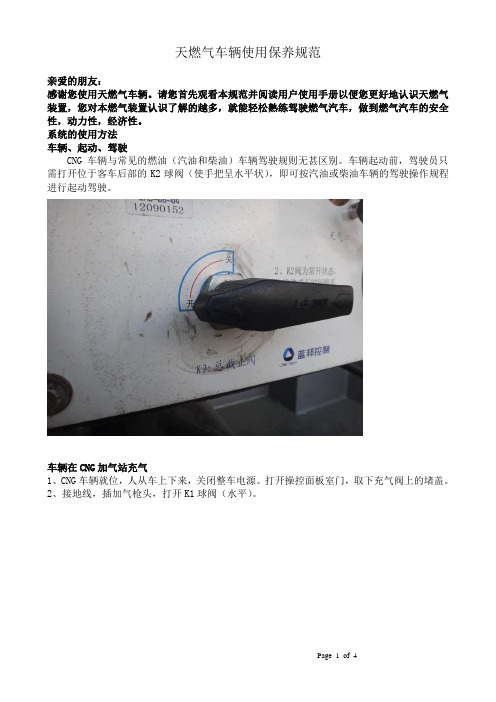
系统的使用方法车辆、起动、驾驶CNG车辆与常见的燃油(汽油和柴油)车辆驾驶规则无甚区别。
车辆起动前,驾驶员只需打开位于客车后部的K2球阀(使手把呈水平状),即可按汽油或柴油车辆的驾驶操作规程进行起动驾驶。
车辆在CNG加气站充气1、CNG车辆就位,人从车上下来,关闭整车电源。
打开操控面板室门,取下充气阀上的堵盖。
2、接地线,插加气枪头,打开K1球阀(水平)。
3、开始充气,充到20MPa,停止充气,关闭球阀(手把呈垂直状)拔下枪头。
4、套上充气阀堵盖,关闭操控面板室门。
5、车辆驶离加气站区。
注意:a、充完气的车辆(充气至20MPa)放置6小时后,压力降低至18~17MPa,是正常的,因系统温度下降所致;b、加气时,应严格执行CNG加气站的操作规程,CNG的充气压力不得高于20MPa,c、若储气瓶组压力为零,则必须充装氮气置换储气系统内的CNG残气后,方可再次充装CNG。
D、在车辆充气过程中,必须关断车辆总电源,周边严禁烟火。
车辆停驶CNG车辆停驶超过12小时,则需驾驶员,在离车时关掉位于客车后部的球阀(使手把呈垂直状)。
CNG车辆停驶超过一周时间,则需驾驶员除关闭位于客车后部的球阀(使手把呈垂直状)外,尚需关闭全部气瓶阀门,以确保车辆的安全。
CNG车辆紧急状态下的处理方法CNG车辆在行驶中发现燃气供给系统有损坏,CNG气体发生泄漏;若嗅到或发现CNG气体发生泄漏时:应立即靠边停车关闭发动机、关断总电源、关闭CNG储气瓶手动截止阀、联系报修;待专业人员到来检修无泄漏后,方可继续行驶;CNG高压管路破裂、CNG气瓶或系统中的高压配件脱落,在系统过流保护装置失效造成CNG气体大量泄漏时:立即疏散车上人员;关断总电源;关闭CNG储气瓶手动截止阀;紧急报修;封闭现场,不准车辆、行人靠近,严格控制并隔离火源,待抢修车排除险情后,方可移动车辆;车辆行驶中,发生火灾:1.立即疏散人员,救护伤员;2.迅速切断总电源、关闭CNG储气瓶手动截止阀;3、迅速报警、同时用车上灭火器进行灭火。
天然气有限公司设备操作维护作业指导书
天然气有限公司设备操作维护作业指导书1. 作业目的本操作维护作业指导书旨在规范天然气有限公司设备操作维护作业,确保设备安全运行,延长设备使用寿命,提高工作效率。
2. 作业范围本指导书适用于天然气有限公司所有设备的操作维护作业,包括但不限于天然气生产设备、管道设备、压缩机等。
3. 作业程序3.1 操作前检查在进行设备操作之前,必须进行设备的全面检查,确认设备无异常情况并且操作部位无异物。
如发现异常情况,应及时报告设备管理员,不得擅自操作设备。
3.2 操作规范操作人员应按照设备操作规程进行操作,并严格遵守操作安全规定,不得违章操作,必须穿戴好安全防护用具进行作业。
3.3 维护保养定期对设备进行维护保养,按照设备维护手册要求对设备进行加油、润滑、清洁等维护工作,确保设备处于良好的工作状态。
3.4 操作后清理操作结束后,必须将设备周围的工具、材料清理干净,保持操作现场整洁,防止发生安全事故。
4. 作业安全4.1 操作人员应严格遵守设备操作规程,不得擅自操作不熟悉的设备。
4.2 在操作过程中,如发现异常情况,应立即停止操作并报告设备管理员。
4.3 对于涉及高空、高压等危险作业的设备,操作人员必须经过专门培训并取得相关证书方可操作。
4.4 在操作现场,禁止吸烟、乱扔废弃物等行为,确保操作现场安全整洁。
5. 作业记录每次操作维护作业结束后,操作人员必须填写作业记录,包括设备操作情况、维护保养情况等,并由操作人员签字确认。
6. 附则6.1 本指导书由设备管理员负责解释和管理,并对操作人员进行培训和考核。
6.2 本指导书内容应严格执行,如有违反,相关责任人将受到相应的纪律处罚。
天然气有限公司设备操作维护作业指导书如上,严格遵守作业规程,确保设备的安全运行,提高设备的使用寿命和工作效率。
7. 设备操作培训为确保所有操作人员具有相关的操作技能和安全意识,天然气有限公司将组织定期的设备操作培训。
培训内容包括设备操作规程、安全操作要求、应急处理措施等,培训结束后,经过考核合格的操作人员才能获得相应的操作资格证书。
- 1、下载文档前请自行甄别文档内容的完整性,平台不提供额外的编辑、内容补充、找答案等附加服务。
- 2、"仅部分预览"的文档,不可在线预览部分如存在完整性等问题,可反馈申请退款(可完整预览的文档不适用该条件!)。
- 3、如文档侵犯您的权益,请联系客服反馈,我们会尽快为您处理(人工客服工作时间:9:00-18:30)。
天然气汽车操作及维护手册
第一章天然气汽车专用装置简介
第一节 CNG及天然汽车
一、CNG是压缩天然气的英文单词缩写。
压缩天然气一般指经多次加压到250MPa左右可供车辆发动机作为燃料使用的气态天然气(甲烷这主要成分)。
在汽车上,CNG的储存方式一般采用高压气瓶储存,车载气瓶最高储存压力这20Mpa。
二、天然气汽车是原燃油汽车的基础上加装一套CNG燃料专用装置系统,具有燃油/燃气两套独立的燃料供给系统的汽车。
此类燃用油时,不能同时使用CNG作为发动机的燃料;反之,燃用CNG也不能混烧油料。
一般简称为天然气汽车(或CNG汽车),英文缩写为CNG。
三、天然气汽车具有节约石油资源、节约燃料引用,降低营运成本、减少减少尾气污染等优点。
不足是动性略有下降,使用中应该加强对高压储气系统的定期安全检验。
第二节天然气汽车专用装置的系统组成
一、CNG专用装置可分为三大系统组成:储存系统、供气系统、燃料转换控制系统。
二、天然气储气系统:由天然气储气瓶、充气阀、高压截止阀、高压管线、高压接头、压力传感器及显示器等组成。
四、供气系统:由燃气截止阀、减压调节器、混合器(或燃气喷)、功率调节阀(动力阀或步进电机)、低压燃气软管。
五、天然气燃料转换控制系统:由油气转换开关、燃气控制ECU(仿真器)、电动油泵(或汽油电磁阀)、点火时间提前器、压力传感器及显示器等组成。
六、化油器车和电喷车CNG系统图如下:
第三节储气系统主要部件及功用
一、压缩天然气储气瓶
(一)储气—是储存压缩天然气(CNG)的专用气瓶。
(二)根据材质和结构不同可分为四种:第一种是钢质气瓶;第二种是钢质内胆环向缠绕气瓶;第三种是铝质内胆全缠绕气瓶;第四种是塑料内胆全缠绕气瓶。
(三)车用压缩天然气储气瓶,配置有熔点为95—105的易熔赛和破损压力为25—30Mpa的安全防爆膜片,当气瓶内的压力、温度超过上述数值时会自动放气泄压,以保证气瓶使用安全。
二、充气阀
充气阀——是加气机与车用气瓶的接口阀。
三、高压电磁阀及高压截止阀
(一)高压电磁阀——采用电控方式接通和截断天然气气路,起开关及保护作用。
(二)手动高压截止阀——用手控方式来控制储气瓶到减压调节器之间气路的接通或截止。
一向用于多气瓶组合的车辆。
四、压力传感器
压力传感器——为燃料显示转换开关提供储气瓶内压力信号的装置。
使显示开关能正确的实时显示储气系统的储气压力,间接指示出气瓶内大概剩余气量。
第四节供气系统主要部件及功用
一、减压调节器
减压调节器——将储气内的高压天然气经过逐级减压至适应发动机工作需要的稳定供气压力的装置。
二、混合器
混合器——将来自减压调节器的低压天然气与空气混合,形成可燃混合气,供给发动机使用的装置。
三、动力调节阀
(一)动力调节阀——在改装和维修时,操作者根据不同的车型或车况,对进入发动机的混合气空燃比进行手动粗略调节的部件,又称功率调节阀。
(二)动力调节阀一般安装在减压调节器与混合器之间的低压管路上,在闭环控制燃气供给系统中还没有由燃气ECU控制的能随发动机工况自动调节供气量的步进电机型动力调节阀。
第五节燃料转换系统主要部件及功用
一、燃料转换开关
(一)燃料转换开关——用于实现油气之间相互转换的装置。
(二)燃料转换开关向驾驶员显示储气系统内当前剩余气量。
二、喷油头、氧传感模拟仿真器
模拟油系统喷油嘴、氧传感器工作状态信号,反馈给ECU实现开环控制(电喷车用),控制CNG系统正常工作的装置。
第二章天然气汽车的安全驾驶操作
一、天然气汽车驾驶员,必须经过使用天然气汽车的技术培训,掌握天然气汽车日常安全检查知识,安全驾驶技术要点,并取得培训合格证后方可驾驶天然气汽车。
二、天然汽车,运行时驾驶操作与一般的汽柴油车驾驶操作基本相同,驾驶时只增加
了一个油气转换操作。
第一节天然气汽车出车前的检查
一、检查汽油和天然气的储量
(一)检查油箱内应有适量存油。
(二)检查气量显示与停车前观察到的气量指示值上否基本一致,确认CNG管路接头是否存在微漏气隐患。
(三)检查驾驶室转换开关所外的工作位置(气或油)。
三、检查储气瓶和高、低压管路上否有泄漏
(一)打开发动机机盖及后备箱,凭嗅觉闻一闻,必要时使用洗涤剂(或肥皂)泡沫水检查所有鬼迷心窍线连接接头是否有泄漏。
(二)若有异味、漏气,应关闭储气并有上的手动截止阀,然后燃用汽油行驶到定点改装厂、特给维修站进行维修。
第二节天然气汽车的起动
一、用汽油起动
(一)电喷汽车的起动:
1、两用燃料车的起动方式多数均设计这:无论油气燃料转换开关置于油挡或气挡,只要油箱里有汽油,ECU均自动采用油起动工作方式。
2、因此,起动时油气燃料转换开关置于油、气挡均可,点火开关钥匙旋转到起动挡即可起动发动机。
3、如果起动时油气燃料转换开关置于油挡,待车辆预热后,踏油门踏板使发动机转速上升到一定范围,ECU将自动从燃油转换为燃气工况。
(二)化油器汽车的起动:
1、把油气燃料转换开关置于油挡(关闭CNG气路截止阀),点火开关钥匙旋转到起动接即可用燃油起动发电机。
对使用非电控截止阀的车辆,应先关闭CNG气路截止阀,再运行起动。
2、如果是机械油泵的化油器,化油器浮子室中没有汽油时需要适当延长点火时间,机械油泵才能将汽油引到化油器浮子室内,发动机才能正常起动。
若是电子油泵的则按正常起动操作即可。
二、用天然气起动
(一)电喷两用燃料汽车的起动
1、一些两用燃料车的起动方式设计为:将油气燃料转换开关置于气挡,点火开关。