TINA中文版说明
LEDiL FA10887_TINA-RS 产品数据表说明书
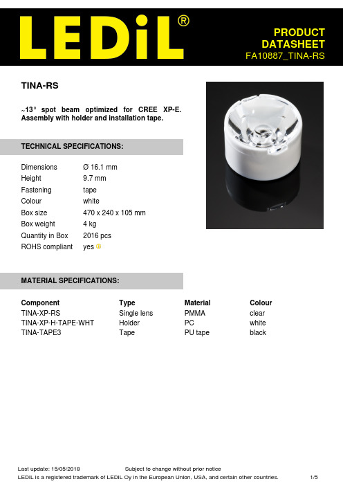
TINA-RS~13° spot beam optimized for CREE XP-E.Assembly with holder and installation tape.TECHNICAL SPECIFICATIONS:DimensionsØ 16.1 mmHeight9.7 mmFastening tapeColour whiteBox size470 x 240 x 105 mmBox weight 4 kgQuantity in Box2016 pcsROHS compliant yesMATERIAL SPECIFICATIONS:Component Type Material Colour TINA-XP-RS Single lens PMMA clear TINA-XP-H-TAPE-WHT Holder PC white TINA-TAPE3Tape PU tape blackPHOTOMETRIC DATA (MEASURED):LED XP-EFWHM10.0°Efficiency93 %Peak intensity18.300 cd/lmLEDs/each optic1Light colour WhiteRequired components:LED XP-GFWHM15.0°Efficiency94 %Peak intensity11.100 cd/lmLEDs/each optic1Light colour WhiteRequired components:PHOTOMETRIC DATA (SIMULATED):LED XD16FWHM12.0°Efficiency92 %Peak intensity13.170 cd/lmLEDs/each optic1Light colour WhiteRequired components:LED XP-G3FWHM16.0°Efficiency87 %Peak intensity7.300 cd/lmLEDs/each optic1Light colour WhiteRequired components:LED Z5FWHM11.0°Efficiency %Peak intensity cd/lmLEDs/each optic1Light colour WhiteRequired components:LED Z5M1/Z5M2FWHM14.0°Efficiency94 %Peak intensity10.790 cd/lmLEDs/each optic1Light colour WhiteRequired components:GENERAL INFORMATION:NOTE: The typical beam angle will be changed by different color, chip size and chip position tolerance. The typical total beam angle is the full angle measured where the luminous intensity is half of the peak value.MATERIALS:As part of our continuous research and improvement processes, and to ensure the best possible quality and availability of our products, LEDiL reserves the right to change material grades without notice.PRODUCT DATA USER AGREEMENT AND DISCLAIMER:The measured data in the provided downloadable LEDiL Product Datasheets and Mechanical 2D-Drawings is rounded and provided as reference for planning. LEDiL Oy's optical specifications have been verified by conducting performance testing of the products in accordance with the company's quality system. The reported data are averaged results of multiple measurements with typical variation. LEDiL Oy reserves the right to without prior notification make changes and improvements to its products.LEDiL Oy assumes neither warranty, nor guarantee nor any other liability of any kind for the contents and correctness of the provided data. The provided data has been generated with highest diligence but the provided data may in reality not represent the complete possible variation range of all intrinsic parameters. Therefore, in certain cases a deviation from the provided data could occur.LEDiL Oy reserves the right to undertake technical changes of its products without further notification which could lead to changes in the provided data. LEDiL Oy assumes no liability of any kind for the possible deviation from any provided data or any other damage resulting from the usage of the provided data.The user agrees to this disclaimer and user agreement with the download or usage of the provided files.LEDiL OyJoensuunkatu 13FI-24240 SALOFinlandLEDiL Inc.228 West Page Street Suite DSycamore IL 60178USALocal sales and technical support/where_to_buyShipping locations Salo, FinlandHong Kong, ChinaDistribution Partners /where_to_buy。
tina入门中文版

1.h TI webpage ed TINA-TI version are:000/XPA–August 2007–RevisedAugust 2008Submit Documentation FeedbackZHCU008 –2007年8月–2008年8月修订TINA-TI™入门 1提交文档反1Overview This quick-start user's guide presents an overview of TINA-TI™,a powerful circuit design and simulation tool.TINA-TI is ideal for designing,testing,and troubleshooting a broad variety of basic and advanced circuits,including complex architectures,without any node or number of device limitations.This documentis intended to help new TINA-TI users start creating circuit simulations using the fundamental features of TINA-TI software in the shortest possible time.Contents 1Overview ......................................................................................................................12Schematic Editor .............................................................................................................23Building a Circuit with TINA-TI .............................................................................................34Analysis Capabilities ........................................................................................................65Test and Measurement .....................................................................................................96AdditionalAssistance ......................................................................................................10List of Figures 1DownloadingTINA-TI (2)2TINA-TI Schematic Editor Display .........................................................................................33Building a Circuit with TINA-TI .............................................................................................44Active and Passive Component Selection ................................................................................55Wiring Components Together ..............................................................................................66DC Analysis with Voltages/Currents Table Displayed ..................................................................77Additional TINA .....................................................................................88Virtual Instrumentation Testing (99)Contextual Help in TINA-TI ...............................................................................................10Texas Instruments has teamed up with DesignSoft,Inc.to provide our customers with TINA-TI,a powerful circuit simulation tool that is well-suited for simulating analog and switched-mode power supply (SMPS)circuits.The tool is ideal for helping designers and engineers to develop and test circuit ideas.TI selected the TINA™simulation software over other SPICE-based simulators for its combination of powerful analysis capabilities,simple and intuitive graphics-based interface,and ease of use,allowing you to be up and running in minimal time.If you are familiar with another SPICE simulator,adapting to TINA-TI should be an easy and straighforward transition.Although TINA-TI is a limited version of more powerful DesignSoft simulation products,it easily handles surprisingly complex circuits.Texas Instruments does not warrant or support any DesignSoft product.TINA-TI is a software program developed by both TI and DesignSoft.For more information about DesignSoft,visit the DesignSoft website at .TINA-TI is a trademark of Texas Instruments and DesignSoft,Inc.TINA is a trademark of DesignSoft,Inc.Windows is a registered trademark of Microsoft Corporation.All other trademarks are the property of their respective owners.SBOU052A–August 2007–Revised August 2008Getting Started with TINA-TI™1Submit Documentation Feedback这本用户快速入门指南概要性的介绍了TINA-TI™——一个强大的电路设计及仿真工具。
TINA用户手册---中文版
1.h TI webpage ed TINA-TI version are:000/XPA–August 2007–RevisedAugust 2008Submit Documentation FeedbackZHCU008 –2007年8月–2008年8月修订TINA-TI™入门 1提交文档反1Overview This quick-start user's guide presents an overview of TINA-TI™,a powerful circuit design and simulation tool.TINA-TI is ideal for designing,testing,and troubleshooting a broad variety of basic and advanced circuits,including complex architectures,without any node or number of device limitations.This documentis intended to help new TINA-TI users start creating circuit simulations using the fundamental features of TINA-TI software in the shortest possible time.Contents 1Overview ......................................................................................................................12Schematic Editor .............................................................................................................23Building a Circuit with TINA-TI .............................................................................................34Analysis Capabilities ........................................................................................................65Test and Measurement .....................................................................................................96AdditionalAssistance ......................................................................................................10List of Figures 1DownloadingTINA-TI (2)2TINA-TI Schematic Editor Display .........................................................................................33Building a Circuit with TINA-TI .............................................................................................44Active and Passive Component Selection ................................................................................55Wiring Components Together ..............................................................................................66DC Analysis with Voltages/Currents Table Displayed ..................................................................77Additional TINA .....................................................................................88Virtual Instrumentation Testing (99)Contextual Help in TINA-TI ...............................................................................................10Texas Instruments has teamed up with DesignSoft,Inc.to provide our customers with TINA-TI,a powerful circuit simulation tool that is well-suited for simulating analog and switched-mode power supply (SMPS)circuits.The tool is ideal for helping designers and engineers to develop and test circuit ideas.TI selected the TINA™simulation software over other SPICE-based simulators for its combination of powerful analysis capabilities,simple and intuitive graphics-based interface,and ease of use,allowing you to be up and running in minimal time.If you are familiar with another SPICE simulator,adapting to TINA-TI should be an easy and straighforward transition.Although TINA-TI is a limited version of more powerful DesignSoft simulation products,it easily handles surprisingly complex circuits.Texas Instruments does not warrant or support any DesignSoft product.TINA-TI is a software program developed by both TI and DesignSoft.For more information about DesignSoft,visit the DesignSoft website at .TINA-TI is a trademark of Texas Instruments and DesignSoft,Inc.TINA is a trademark of DesignSoft,Inc.Windows is a registered trademark of Microsoft Corporation.All other trademarks are the property of their respective owners.SBOU052A–August 2007–Revised August 2008Getting Started with TINA-TI™1Submit Documentation Feedback这本用户快速入门指南概要性的介绍了TINA-TI™——一个强大的电路设计及仿真工具。
Tina Linux 系统软件 开发指南说明书
Tina Linux系统软件开发指南版本号:1.5发布日期:2021.04.17版本号日期制/修订人内容描述0.12019.02.20AWA1225创建1.02019.02.27AWA1225正式发布1.12019.06.16AWA1046补充软件包安装,烧录工具及分区说明1.22019.06.19AWA1046更新文档说明和目录结构说明,补充细节1.32020.12.31AWA1610增加arisc代码编译描述1.42021.02.06AWA1610arisc代码编译策略变更1.52021.04.17AWA0985完善部分章节描述1概述11.1编写目的 (1)1.2适用范围 (1)1.3相关人员 (1)2Tina系统资料22.1概述 (2)2.2文档列表 (2)3Tina系统概述33.1概述 (3)3.2系统框图 (3)3.3开发流程 (4)4Tina开发环境64.1概述 (6)4.2编译环境搭建 (6)4.2.1开发主机配置 (6)4.2.2软件包配置 (6)5Tina系统获取85.1概述 (8)5.2SDK获取 (8)5.3SDK结构 (8)5.3.1build目录 (8)5.3.2config目录 (9)5.3.3devices目录 (9)5.3.4docs目录 (10)5.3.5lichee目录 (10)5.3.6package目录 (10)5.3.7prebuilt目录 (11)5.3.8scripts目录 (11)5.3.9target目录 (11)5.3.10toolchain目录 (12)5.3.11tools目录 (12)5.3.12out目录 (12)5.4SDK更新 (13)5.5问题反馈 (13)6Tina编译打包156.1概述 (15)6.2编译系统 (15)6.3编译boot (15)6.4编译内核 (15)6.5编译arisc (16)6.6重编应用 (17)6.6.1方法一 (17)6.6.2方法二 (17)6.7其他命令 (18)7Tina系统烧写197.1概述 (19)7.2烧录工具 (19)7.3进入烧录模式 (19)8Tina uboot定制开发218.1概述 (21)8.2代码路径 (21)8.3uboot功能 (21)8.4uboot配置 (22)8.4.1defconfig方式 (22)8.4.1.1defconfig配置步骤 (22)8.4.1.2defconfig配置宏介绍 (22)8.4.2menuconfig方式 (23)8.5uboot编译 (24)8.5.1方法一 (24)8.5.2方法二 (25)8.6uboot的配置 (25)8.6.1sys_config配置 (25)8.6.1.1sys_config.fex结构介绍 (25)8.6.1.2sys_config.fex配置实例 (25)8.6.1.3sys_config.fex解析流程 (26)8.6.2环境变量配置 (26)8.6.2.1环境变量作用 (27)8.6.2.2环境变量配置示例介绍 (27)8.6.3sys_partition.fex分区配置 (28)8.6.3.1sys_partition.fex分区配置介绍 (28)9Tina kernel定制开发299.1概述 (29)9.2代码路径 (29)9.3模块开发文档 (29)9.4内核配置 (29)10Tina系统定制开发3110.1应用移植 (31)10.1.1Makefile范例 (31)10.1.2自启动设置 (33)10.1.2.1调用自启动脚本 (33)10.1.2.2sysV格式脚本 (33)10.1.2.3procd格式脚本 (34)10.2应用调试 (35)10.3应用编译 (36)10.4应用安装 (36)10.5分区与挂载 (37)3-1Tina Linux系统框图 (3)3-2Tina Linux系统开发流程 (4)8-1defconfig配置图 (22)8-2defconfig基本宏定义介绍图 (23)8-3menuconfig配置菜单图 (24)8-4sysconfig.fex基本结构图 (25)8-5platform配置图 (26)8-6target配置图 (26)8-7uart_para配置图 (26)8-8uboot启动调用环境变量方式图 (27)8-9kernel cmdline图 (28)9-1TinaLinux内核配置菜单 (30)10-1应用配置主界面 (35)10-2软件包所在界面 (36)1.1编写目的本文档作为Allwinner Tina Linux系统平台开发指南,旨在帮助软件开发工程师、技术支持工程师快速上手,熟悉Tina Linux系统的开发及调试流程。
Tina备份软件简单维护说明

Tina简单维护手册目录一、新建节点 (2)1、添加hostname至hosts配置文件 (2)2、安装客户端 (3)3、主机端添加扫描 (13)4、创建策略 (17)二、删除节点 (21)三、其它操作 (24)1、清除磁带内容 (24)2、把驱动器中的磁带弹出至原槽位。
(27)3、新建介质池 (27)4、删除策略 (28)5、恢复文件 (28)一、新建节点新建节点步骤:1、添加hostname至hosts配置文件2、安装客户端3、主机端添加扫描4、创建策略详细步骤:1、添加hostname至hosts配置文件Tina备份软件的通讯是依靠hostname主机名来进行通讯的,所以客户端主机名必须唯一,并且不能为locahosts等特殊定义的主机名。
备份服务器和客户端主机都需要添加对方的主机名。
在客户端主机(beifen123)的hosts文件中添加备份服务器主机名(BACKUPSERVER-HB)在备份服务器中的hosts文件添加客户端主机hostname2、安装客户端在unix、linux中安装客户端软件时,可以通过两种交互模式安装,一种是图形交互模式,根据弹出的对话框填写信息并完成,另一种是文本交互模式,文本交互模式多用于系统没有安装图形化组件时使用。
图形化安装安装前准备工作:安腾普软件通过主机名进行解析,在安装前编辑hosts表添加备份服务器和自身的主机名[root@BlueWhale-1 atninstall]# chmod +x ATN433-P5292B-Linux-X64.bin[root@BlueWhale-1 ~]# more /etc/hosts127.0.0.1 localhost localhost.localdomain::1 localhost localhost.localdomain10.53.12.39 BlueWhale-110.53.12.37 backupserver[root@BlueWhale-1 ~]#确认无误后,执行安装文件./ATN433-P5292B-AIX61.bin启动安装过程[root@BlueWhale-1 atninstall]# ./ATN433-P5292B-AIX61.bin◆因为是服务器的角色是客户端,因为这里选择客户端安装◆如果客户端和备份服务器在一个网段内,软件会通过广播自动发现,如果不在一个网段内,有时需要手工添加服务器手工添加时参数如下,服务器的名字和catalog名也和备份服务器的一致选择安装的模块根据客户端的应用情况,可以选择默认安装在备份服务器端也需要填写host表,用于主机解析文本模式安装说明:1.修改客户端和服务器端hosts文件,添加相应主机名,注意要把客户端主机的主机名也添加到本地hosts文件中2.把程序包和batch_install上传至客户端相应目录(两个文件放在一起),修改其权限3.进入程序所在目录,执行如下命令 ./ATN433-P5292B-AIX61.bin -f batch_install.txt4.拷贝备份服务器安装目录”C:\Program Files\TINA\TINA\tina\Conf“下的catalog.txt,复制一份改名为catalog(注意,去掉.txt)至unix相应的安装目录下,如:/usr/Atempo/TINA/tina/Conf下,覆盖即可5.后续步骤和图形化步骤一样,在服务器端自动发现或手动添加客户端脚本如下附件batch_install.txt文本交换机模式详细步骤:上传安装文件和脚本修改权限执行安装查看进程是否启动替换catalogs文件先删除/usr/Atempo/TINA/tina/Conf目录下的catalogs上传备份服务器中备份软件中的catalogs文件,并把上传的catalogs.txt修改为catalogs,(去掉了后边的.txt)。
tina使用说明
1OverviewQuick Start GuideSBOU052–August 2007This quick start user's guide presents an overview of TINA-TI™,a powerful circuit design and simulation tool.TINA-TI is ideal for designing,testing,and troubleshooting a broad variety of basic and advanced circuits,including complex architectures,without any node or number of device limitations.This document is intended to help new TINA-TI users start creating circuit simulations using the fundamental features of TINA-TI software in the shortest possible time.Contents 1Overview (12)Schematic Editor (23)Building a Circuit with TINA-TI (34)Analysis Capabilities (65)Test and Measurement .....................................................................................................96Additional Assistance (10)List of Figures1Downloading TINA-TI (22)TINA-TI Schematic Editor Display (33)Building a Circuit with TINA-TI (44)Active and Passive Component Selection (55)Wiring Components Together (66)DC Analysis with Voltages/Currents Table Displayed (77)Additional TINA Analysis Capabilities (88)Virtual Instrumentation Testing .............................................................................................99Contextual Help in TINA-TI ...............................................................................................10Texas Instruments has teamed up with DesignSoft,Inc.to provide our customers with TINA-TI,a powerful circuit simulation tool that is well-suited for simulating analog and switched-mode power supply (SMPS)circuits.The tool is ideal for helping designers and engineers to develop and test circuit ideas.TI selected the TINA™simulation software over other SPICE-based simulators for its combination of powerful analysis capabilities,simple and intuitive graphics-based interface,and ease of use,allowing you to be up and running in minimal time.If you are familiar with another SPICE simulator,adapting to TINA-TI should be an easy and straighforward transition.Although TINA-TI is a limited version of more powerful DesignSoft simulation products,it easily handles surprisingly complex circuits.Texas Instruments does not warrant or support any DesignSoft product.TINA-TI is a software program For more information about DesignSoft,visit the DesignSoft website at TINA-TI is a trademark of Texas Instruments and DesignSoft,Inc.TINA is a trademark of DesignSoft,Inc.Windows is a registered trademark of Microsoft Corporation.All other trademarks are the property of their respective owners. Schematic Editor2Schematic EditorYou can download TINA-TI as shown in Figure1.Alternatively,it is availablethrough the TI home page at the a summary of TINA-TI related information.you to theFigure1.Downloading TINA-TIThe minimum hardware and software requirements for the currently released TINA-TI version are:•IBM PC-compatible computer running Microsoft Windows®98/ME/NT/2000/XP•Pentium or equivalent processor•64MB of RAM•Hard disk drive with at least100MB free space•Mouse•VGA adapter card and monitor2Getting Started with TINA-TI™SBOU052–August20073Building a Circuit with TINA-TIBuilding a Circuit with TINA-TIOnce the software is downloaded to your system,select the program through the Windows Start menu or click on the TINA-TIicon on your desktop that was created during the installation.The first screen appears as shown in Figure 2.Figure 2.TINA-TI Schematic Editor DisplayFigure 2shows the schematic editor layout.The empty workspace on the sheet is the design windowbuild the test circuit.Below the Schematic Editor title bar is an operational menu row withselections such as file operations,analytical operations,test and measurement equipment selection,etc.Located just below the menu row is a row of icons associated with different file and TINA tasks.The final row of icons allows you to select a specific component group.These component groups contain basicpassive components,semiconductors,and even sophisticated device macromodels.These groups areaccessed to build the circuit schematic.To illustrate how easy it is to use TINA-TI,we will build an analog circuit and demonstrate some of thecircuit analysis capabilities.For this example,a high-output,1kHz sine wave oscillator circuit is selected.A search through a circuitapplication handbook provides a number of op amp-based designs.We will build and Wein-bridge oscillator with amplitude stabilization using the software.A Texas Instruments'12V CMOS op amp is selected for the circuit application.This amplifier is well-suited for this provides very good dc and ac performance.It operates with supplies of 3.5V to 12V;our example requires ±5V (10V). Building a Circuit with TINA-TISelect the Spice Macros tab(see Figure3,step1)and then the op amp symbol(step2)to access the OPA743macromodel.When the list appears,scroll down and click on the OPA743(step3).Then click OK.The op amp symbol appears in the circuit workspace.With the mouse,drag the symbolinto position(step4).It is locked into position on the circuit workspace by clicking the left mouse button.Figure3.Building a Circuit with TINA-TIOther op amp models may be selected using the Insert->Macro...menu.Additionally,macros and a wide variety of pre-built analog and SMPS circuits can be accessed through the Insert menu.(Insert->Macro...TinaTI_7.0->Examples).4Getting Started with TINA-TI™SBOU052–August2007Building a Circuit with TINA-TI 3.1Adding Passive and Active ComponentsComponent selection is easily accomplished by clicking on a component group from the lower row of tabs: Basic,Switches,Meters,and so forth.These tabs provide a wide variety of passive components,sources, meters,relays,semiconductors,and the previously-mentioned circuit macros.Click on the schematicsymbol for a particular component and drag it into position in the circuit workspace.A left mouse button click locks it into place.In our example,shown in Figure4,we select a resistor from the Basic tab group(step1and step2),then position it next to the op TINA-TI designates this resistor as R1.The initial value of R1is1kΩ,but this value can be changed as needed.A double-click with the left mouse button on the R1symbol produces the associated component table(step3).Figure4.Active and Passive Component SelectionThe resistor value and other component characteristics may be altered by selecting the individualparameter boxes and changing the respective values.Select the component parameter box and highlight the value you wish to change.Enter a new value by typing over the value that is shown.In Figure4,for example,the value for R1has been changed from1k to4.7k for this circuit.Once yousetting the parameters,click OK to close the table.Similar parametric tables are available for passivedevices,sources,semiconductors,and other component types.A handy component that is displayed in the Basic group is the jumper,as shown in Figure4.It looks like asideways letter T.The jumper may be used to connect similar,related circuit as V+,V–,or any other circuit point that has multiple ing the jumper reduces wiring clutter.Note that common jumpers must be labeled with the same label name for TINA-TI to connect them together.3.2Arranging and WiringComponents4Analysis CapabilitiesAnalysis CapabilitiesOnce all components are selected and properly positioned,they can be wired together.Each component has nodes where circuit connections are needed.TINA displays these nodes with a small red x .(The x looks more like two small lines at the wiring node than the alpha character.)Wiring components to each other is easily done by placing the mouse pointer over a node connection and holding the left mousebutton down.A wire is drawn as the mouse is moved along the circuit space grid.Release the mousebutton when the wire reaches the intended end connection point.Figure 5illustrates the TINA-TI software wiring function.Figure 5.Wiring Components TogetherThe wiring function also may be accessed from the Insert menu,or the icon that looks like a small pencil.When the circuit schematic entry is complete,the circuit is nearly ready for simulation.The analysisprocess begins by selecting the Analysis menu.A list of different types of analyses—such as ac,dc,transient,or noise—appears.Highlight any one of these evaluations to access additional options andselections.The first option under the Analysis menu is an Error Rules Check (ERC).Selecting this feature runs this check on the circuit;a pop-up window then lists any circuit errors.If an error is listed in the window,clicking on that error line highlights the error point in the schematic.The error window also lists other types of circuit errors that are found during the analysis.6Getting Started with TINA-TI™SBOU052–August 20074.1DCAnalysisAnalysis CapabilitiesEven if the ERC is not selected,TINA automatically performs a check at the start of a simulation.Upon selecting one type of analysis to perform,another window appears that displays different settingselections that are associated with that particular analysis.Nominal settings are initially provided;theseparameters may be set as needed for the desired output.Once all of the selections are made,click OK to begin the analysis.The first analysis performed on acircuit is generally a dc analysis.This test provides a reality check so that normal dc operating conditions can be verified.The TINA-TI DC Analysis function can be set to calculate nodal voltages,provide a table of dc voltage and current results,generate a dc sweep of the circuit,or perform a temperature analysis.The temperature analysis works in combination with the Analysis >Mode >temperature-steppingselections.Follow these steps (illustrated in Figure 6)to perform a dc analysis.1.Click on the Analysis menu.2.Select DC Analysis .3.Click on Table of DC Results .The Voltages/Currents table appears.e the mouse pointer as a probe to test the circuit nodes.The probed node and measured value are displayed in red in the Voltages/Currents table,as shown inFigure 6.Figure 6.DC Analysis with Voltages/Currents Table Displayed Analysis Capabilities4.2Transient AnalysisSophisticated ac frequency and time domain simulations may also be e the Analysisfunction to access the different choices.A traditional ac transfer characteristic plot of gain and phaseversus frequency may be selected,as well as transient,Fourier or noise analyses.The example shown in Figure7is a transient analysis performed on the example Wein-bridge oscillator circuit.The simulation analysis result is also shown in Figure7.It illustrates the Wein-bridge oscillator startup and steady-state performance.The display in window may be edited with axis labeling,scales,background grid color,and so forth,all set as desired by the individual user.Follow these steps(marked in Figure7)to perform a transient analysis.1.Click on the Analysis menu.2.Select Transient.3.The Transient Analysis dialog box appears.Enter start and end times,and other parameters asdesired.4.Click OK to run the analysis.Figure7.Additional TINA Analysis Capabilities8SBOU052–August2007 Getting Started with TINA-TI™Test and Measurement 5Test and MeasurementThe TINA-TI software generates post-simulation results in tables and plots,depending on the type ofanalysis performed.Additionally,the software can be placed in a pseudo-real-time simulation mode where virtual instruments can be used to observe the output(s)while the circuit is operating.For example,Figure8shows a virtual oscilloscope that is used to observe the steady-state output of the Wein-bridge circuit.In the same way,a virtual signal analyzer can be used together with anamplifier circuit so that the harmonic performance of a simulation can be observed.To access the virtual oscilloscope,select T&M(step1in Figure8),and then Oscilloscope(step2).Place the cursor at theoutput of the simulated circuit,and controls in the virtual oscilloscope dialog box as needed(step3).The T&M selection options also include a virtual ac/dc multimeter,function generator,and an X-Yrecorder.The function generator may be adjusted in combination with a virtual oscilloscope or analyzer.Figure8.Virtual Instrumentation Testing Additional Assistance6Additional AssistanceTINA-TI has many more features that can be explored.As you become more comfortable with thesimulation software,you will be able to take advantage of these capabilities to build circuits more rapidly, perform more sophisticated simulations,and optimize the output information for a variety of needs.The software also offers on-screen contextual help,and displays mouse-over descriptions for many icons and areas of the workspace,as shown in Figure9.If you need additional assistance with a particularanalysis,or help with setting the active parameters,detailed help documentation is available.Click on the Help menu to access information associated with circuit analysis,active components,and so forth.Further assistance for specific TINA-TI application simulations is available by contacting your local TI technical representative.Figure9.Contextual Help in TINA-TINote:Texas Instruments does not offer support for TINA software.Contact youhave questions or need assistance with general TINA software10Getting Started with TINA-TI™SBOU052–August2007IMPORTANT NOTICETexas Instruments Incorporated and its subsidiaries(TI)reserve the right to make corrections,modifications,enhancements,improvements, and other changes to its products and services at any time and to discontinue any product or service without notice.Customers should obtain the latest relevant information before placing orders and should verify that such information is current and complete.All products are sold subject to TI’s terms and conditions of sale supplied at the time of order acknowledgment.TI warrants performance of its hardware products to the specifications applicable at the time of sale in accordance with TI’s standard warranty.Testing and other quality control techniques are used to the extent TI deems necessary to support this warranty.Except where mandated by government requirements,testing of all parameters of each product is not necessarily performed.TI assumes no liability for applications assistance or customer product design.Customers are responsible for their products and applications using TI components.To minimize the risks associated with customer products and applications,customers should provide adequate design and operating safeguards.TI does not warrant or represent that any license,either express or implied,is granted under any TI patent right,copyright,mask work right, or other TI intellectual property right relating to any combination,machine,or process in which TI products or services are rmation published by TI regarding third-party products or services does not constitute a license from TI to use such products or services or a warranty or endorsement e of such information may require a license from a third party under the patents or other intellectual property of the third party,or a license from TI under the patents or other intellectual property of TI.Reproduction of TI information in TI data books or data sheets is permissible only if reproduction is without alteration and is accompanied by all associated warranties,conditions,limitations,and notices.Reproduction of this information with alteration is an unfair and deceptive business practice.TI is not responsible or liable for such altered rmation of third parties may be subject to additional restrictions.Resale of TI products or services with statements different from or beyond the parameters stated by TI for that product or service voids all express and any implied warranties for the associated TI product or service and is an unfair and deceptive business practice.TI is not responsible or liable for any such statements.TI products are not authorized for use in safety-critical applications(such as life support)where a failure of the TI product would reasonably be expected to cause severe personal injury or death,unless officers of the parties have executed an agreement specifically governing such use.Buyers represent that they have all necessary expertise in the safety and regulatory ramifications of their applications,and acknowledge and agree that they are solely responsible for all legal,regulatory and safety-related requirements concerning their products and any use of TI products in such safety-critical applications,notwithstanding any applications-related information or support that may be provided by TI.Further,Buyers must fully indemnify TI and its representatives against any damages arising out of the use of TI products in such safety-critical applications.TI products are neither designed nor intended for use in military/aerospace applications or environments unless the TI products are specifically designated by TI as military-grade or"enhanced plastic."Only products designated by TI as military-grade meet military specifications.Buyers acknowledge and agree that any such use of TI products which TI has not designated as military-grade is solely at the Buyer's risk,and that they are solely responsible for compliance with all legal and regulatory requirements in connection with such use. TI products are neither designed nor intended for use in automotive applications or environments unless the specific TI products are designated by TI as compliant with ISO/TS16949requirements.Buyers acknowledge and agree that,if they use any non-designated products in automotive applications,TI will not be responsible for any failure to meet such requirements.Following are URLs where you can obtain information on other Texas Instruments products and application solutions:Products ApplicationsAmplifiers AudioData Converters AutomotiveDSP BroadbandInterface Digital ControlLogic MilitaryPower Mgmt Optical NetworkingMicrocontrollers SecurityRFID TelephonyLow Power Wireless Video&ImagingWirelessMailing Address:Texas Instruments,Post Office Box655303,Dallas,Texas75265Copyright©2007,Texas Instruments Incorporated。
全志芯片tina分区说明

全志芯片tina分区说明全志芯片tina是一款先进的嵌入式处理器芯片,广泛应用于智能设备领域。
它具有良好的性能和稳定性,适用于各种不同的应用场景。
为了更好地理解tina芯片的分区说明,我们将从几个方面进行介绍。
我们需要了解tina芯片的整体架构。
tina芯片采用了多核处理器设计,拥有强大的计算能力和高效的能耗管理。
它具有主核和多个辅核,可以同时处理多个任务,提高系统的整体性能。
此外,tina 芯片还集成了丰富的外设接口,可以方便地连接各种外部设备。
tina芯片的分区说明主要包括存储器分区和外设分区两个方面。
存储器分区是指将芯片内部的存储器按照一定的规则进行划分,以满足不同应用的存储需求。
通常,tina芯片的存储器分为内部存储器和外部存储器两部分。
内部存储器主要用于存储程序代码和数据,而外部存储器则用于存储大容量的数据文件。
根据实际需求,可以灵活配置存储器的容量和分区方式。
外设分区是指将芯片上的外设接口按照一定的规则进行划分,以满足不同应用的外设连接需求。
tina芯片提供了多种外设接口,如UART、SPI、I2C和USB等。
这些接口可以连接各种外部设备,如传感器、显示屏和存储设备等。
通过合理划分外设分区,可以方便地进行外设的扩展和使用。
在进行tina芯片的分区配置时,需要根据具体的应用需求进行合理的规划。
首先,我们需要确定存储器分区的大小和分配方式。
一般来说,内部存储器的容量越大,可以存储的程序代码和数据量就越大,系统的性能也会更好。
而外部存储器则可以根据实际存储需求选择合适的容量和类型。
我们需要确定外设分区的数量和连接方式。
外设分区的数量决定了可以连接的外部设备数量,而连接方式则决定了外部设备与芯片之间的通信方式。
在确定外设分区时,需要综合考虑各种因素,如设备的类型、通信速率和功耗等。
我们需要将存储器分区和外设分区进行配置和初始化。
根据tina芯片的分区说明,可以使用相应的软件工具或编程语言进行配置和初始化操作。
TINA-TI基本教程
TINA-TI基本教程内容简介本教程介绍了一个强大的电路设计和仿真工具TINA-TI。
TINA-TI可用于对各种电路进行设计、测试和故障诊断。
这些电路可以是简单的或者高级的具有复杂结构的电路,TINA-TI对它们没有任何节点或器件数量的限制。
本教程主要介绍TINA-TI软件的基本特征和电路仿真方法。
首先介绍了TINA-TI的特点及功能、软件的下载与安装,然后通过一个电路实例介绍了电路原理图编辑,通过另外一个TINA-TI提供的电路示例介绍了电路分析方法以及用虚拟仪器测量电路的方法,最后介绍了TINA-TI的其它辅助功能。
目录1 概述 (3)2 电路示例 (3)2.1 放大器和线性电路: (3)2.2 SMPS(开关式电源): (4)2.3 其它 (4)3 TINA-TI的使用 (4)3.1 下载与安装TINA-TI (4)3.2 启动TINA-TI (5)3.3 搭建电路 (6)3.3.1 电路原理 (6)3.3.2 在原理图中添加元件 (7)3.3.3 添加无源元件 (8)3.3.4 布置元件和连线 (10)3.4 分析电路 (11)3.4.1 直流分析 (13)3.4.2 瞬态分析 (15)3.4.3 交流分析 (16)3.5 测量电路 (18)3.5.1 万用表 (18)3.5.2 示波器 (19)3.5.3 信号分析仪 (19)3.5.4 函数发生器 (21)3.6 TINA-TI的其它辅助功能 (22)1 概述德州仪器公司(TI)与DesignSoft公司联合为客户提供了一个强大的电路仿真工具TINA-TI。
TINA-TI适用于对模拟电路和开关式电源(SMPS)电路的仿真,是进行电路开发与测试的理想选择。
TINA基于SPICE引擎,是一款功能强大而易于使用的电路仿真工具;而TINA-TI 则是完整功能版本的TINA,并加载了TI公司的宏模型以及无源和有源器件模型。
TI之所以选择TINA仿真软件而不是其它的基于SPICE技术的仿真器,是因为它同时具有强大的分析能力和简单直观的图形界面,并且易于使用。
- 1、下载文档前请自行甄别文档内容的完整性,平台不提供额外的编辑、内容补充、找答案等附加服务。
- 2、"仅部分预览"的文档,不可在线预览部分如存在完整性等问题,可反馈申请退款(可完整预览的文档不适用该条件!)。
- 3、如文档侵犯您的权益,请联系客服反馈,我们会尽快为您处理(人工客服工作时间:9:00-18:30)。
1.h TI webpage ed TINA-TI version are:000/XPA–August 2007–RevisedAugust 2008Submit Documentation FeedbackZHCU008 –2007年8月–2008年8月修订TINA-TI™入门 1提交文档反1Overview This quick-start user's guide presents an overview of TINA-TI™,a powerful circuit design and simulation tool.TINA-TI is ideal for designing,testing,and troubleshooting a broad variety of basic and advanced circuits,including complex architectures,without any node or number of device limitations.This documentis intended to help new TINA-TI users start creating circuit simulations using the fundamental features of TINA-TI software in the shortest possible time.Contents 1Overview ......................................................................................................................12Schematic Editor .............................................................................................................23Building a Circuit with TINA-TI .............................................................................................34Analysis Capabilities ........................................................................................................65Test and Measurement .....................................................................................................96AdditionalAssistance ......................................................................................................10List of Figures 1DownloadingTINA-TI (2)2TINA-TI Schematic Editor Display .........................................................................................33Building a Circuit with TINA-TI .............................................................................................44Active and Passive Component Selection ................................................................................55Wiring Components Together ..............................................................................................66DC Analysis with Voltages/Currents Table Displayed ..................................................................77Additional TINA .....................................................................................88Virtual Instrumentation Testing (99)Contextual Help in TINA-TI ...............................................................................................10Texas Instruments has teamed up with DesignSoft,Inc.to provide our customers with TINA-TI,a powerful circuit simulation tool that is well-suited for simulating analog and switched-mode power supply (SMPS)circuits.The tool is ideal for helping designers and engineers to develop and test circuit ideas.TI selected the TINA™simulation software over other SPICE-based simulators for its combination of powerful analysis capabilities,simple and intuitive graphics-based interface,and ease of use,allowing you to be up and running in minimal time.If you are familiar with another SPICE simulator,adapting to TINA-TI should be an easy and straighforward transition.Although TINA-TI is a limited version of more powerful DesignSoft simulation products,it easily handles surprisingly complex circuits.Texas Instruments does not warrant or support any DesignSoft product.TINA-TI is a software program developed by both TI and DesignSoft.For more information about DesignSoft,visit the DesignSoft website at .TINA-TI is a trademark of Texas Instruments and DesignSoft,Inc.TINA is a trademark of DesignSoft,Inc.Windows is a registered trademark of Microsoft Corporation.All other trademarks are the property of their respective owners.SBOU052A–August 2007–Revised August 2008Getting Started with TINA-TI™1Submit Documentation Feedback这本用户快速入门指南概要性的介绍了TINA-TI™——一个强大的电路设计及仿真工具。
TINA-TI 是理想的用于对各种基本的和高级的电路(具有复杂的结构、没有任何节点或器件数量的限制)进行设计、测试和故障诊断的工具。
本文档的目的是,帮助TINA-TI 的新用户在最短的时间内熟悉TINA-TI 软件的基本特征并开始进行电路仿真。
目录图目录123456123456789概述原理图编辑器用 TINA-TI 搭建一个电路分析能力测试与测量其它辅助项下载 TINA-TI TINA-TI 原理图编辑器界面用 TINA-TI 搭建一个电路有源元件和无源元件选择用走线将元件连在一起显示电压/电流列表的直流分析TINA 更多的分析能力虚拟仪器测试TINA-TI 中的语境帮助12369102345678910概述德州仪器与 DesignSoft 公司联手为我们的客户提供 TINA-TI ——一个强大的电路仿真工具,适用于对模拟电路和开关模式电源 (SMPS) 电路的仿真。
它是帮助设计师和工程师们进行电路开发与测试的理想选择。
TI 之所以选择 TINA™ 仿真软件而不是其它的基于 SPICE 技术的仿真器,是因为它同时具有强大的分析能力、简单和直观的图形界面,并且易于使用,可以让你在最短时间内启动并运行。
如果您熟悉其它的 SPICE 仿真器,那么尽快适应 TINA-TI 将会是一个很容易和直接的过程。
尽管 TINA-TI 是更加强大的 DesignSoft 仿真产品中的一个有限版本,它仍能轻松处理极为复杂的电路。
德州仪器不确保或支持任何 DesignSoft 的产品。
TINA-TI 是由 TI 和 DesignSoft 共同开发的软件程序。
如需获得 DesignSoft 的更多信息,敬请访问 DesignSoft 的网站:。