天津诺沃泰克直线位移传感器下载资料F200g_cn
位移传感器资料

位移传感器资料整理一定义位移传感器又称为线性传感器,它分为电感式位移传感器,电容式位移传感器,光电式位移传感器,位移传感器超声波式位移传感器,霍尔式位移传感器。
电感式位移传感器是一种属于金属感应的线性器件,接通电源后,在开关的感应面将产生一个交变磁场,当金属物体接近此感应面时,金属中则产生涡流而吸取了振荡器的能量,使振荡器输出幅度线性衰减,然后根据衰减量的变化来完成无接触检测物体的目的。
二分类2.1 按运动分类型直线位移传感器和角度位移传感器2.2 按材料分类a.金属膜位移传感器b.导电位移传感器c.光电式位移传感器d.磁敏式位移传感器e.金属玻璃铀传感器f.绕线式位移传感器g.电位器位移传感器2.3 广义分类A 机械式1)模拟式电位器式,电阻应变式,电容式,螺旋管电感式,差动变压式,涡流式,光电式,霍尔器件式,微波式,超声波式2)数字式光栅式和磁栅式B 接近式电容式,涡流式,霍尔效应式,光电式,热释电式,多普勒式,电磁感应式,微波式,超声波式C 转速式一般有光电式D 多普勒式E 液位式浮子式,平衡浮筒式,压差电容式,导电式,超声波式,放射式F 流量及流量式 电磁式,涡流式,超声波式,热导式,激光式,光纤式,浮子式,涡轮式,空间滤波式G 激光位移式三 原理及适用范围1. 机械位移传感器a.电位器式如图3.1.1所示为电位器的一般结构。
图3.1.2所示,电位器上电刷将电阻体电阻分成R 12和R 23,输出电压为U 12。
改变电刷的接触位置R 12亦随之改变,输出电压U 12也随着改变。
b.电容式常用的有变极距和变面积两种。
下面以变极距式电容传感器为例(如图3.1.3所示)进行说明。
可动极板移动引起d 发生变化,由C=εA/d 只要测出电容变化量C ∆就可以求出位移变化量d ∆。
c.螺旋管式电感位移传感器原理:螺旋管中铁芯的位移引起电感的变化,从而通过电感的变化量可求出位移的变化量。
24N AL lπμ=(其中l 为插入线圈的铁芯长度)图3.1.2 电位器电路图3.1.1 电位器的一般结构图3.1.3 变极距式电容传感器原理螺旋管电感位移传感器检测位移从数毫米到数百毫米,缺点是灵敏度低。
位移传感器 大学物理实验
实验三十七 位移传感器实验实验目的1. 了解电容式传感器结构及其特点。
2. 了解霍尔效应及其霍尔位移传感器工作原理。
实验原理关于传感器的初步介绍请参见“应变片传感器”的相关内容。
位移传感器的功能在于把机械位移量转换成电信号。
根据不同的物理现象(或物理过程),可以设计不同类型的位移传感器。
本实验首先研究电容位移传感器,在研究与拓展部分再讨论霍尔位移传感器。
1. 电容式传感器基本原理电容式传感器是指能将被测物理量的变化转换为电容量变化的一种传感器。
它实质上是具有一个可变参数的电容器。
利用平板电容器原理:0r SS C ddεεε==(1)式中,S 为极板面积,d 为极板间距离, 为真空介电常数, 为介质相对介电常数。
可以看出:当被测物理量使S 、d 或 发生变化时,电容量C 随之发生改变。
如果保持其中两个参数不变而仅改变另一参数,就可以将该参数的变化单值地转换为电容量的变化。
所以电容传感器可以分为三种类型:改变极间距离的变间隙式,改变极板面积的变面积式和改变介电常数的变介电常数式。
本实验采用变面积式电容传感器。
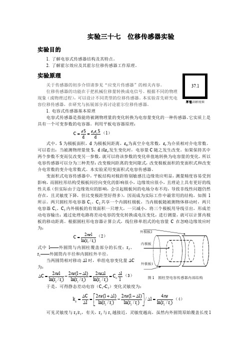
变面积式电容传感器中,平板结构对极距特别敏感且边缘效应明显,测量精度容易受到影响,而圆柱形结构受极板间径向变化的影响很小,边缘效应很小,且理论上具有更好的线性关系(但实际由于边缘效应的影响,会引起极板间的电场分布不均,导致非线性问题仍然存在,且灵敏度下降,但比变极距型好得多),因而成为实际工作中最常用的结构,如图1所示。
两只圆柱形电容器C 1、C 2共享一个内圆柱极板,当内极板随被测物体移动时,两只电容器C 1、C 2内外极板的有效面积一只增大,一只减小,将三个极板用导线引出,形成差动电容输出;通过处理电路将差动电容的变化转换成电压变化,进行测量,就可以计算内极板的移动距离。
根据圆柱形电容器计算公式,线位移单组式的电容量C 在忽略边缘效应时为:212ln(/)l C r r πε=(2) 式中l ——外圆筒与内圆柱覆盖部分的长度;r 2、r 1——外圆筒内半径和内圆柱外半径。
《位移传感器》课件2

磁致伸缩位移传感器具有较快的响应 速度,能够实时监测物体的位移变化 。
磁致伸缩位移传感器的优缺点
• 可靠性高:磁致伸缩位移传感器具有较高的可靠性,能够 在恶劣环境下稳定工作。
磁致伸缩位移传感器的优缺点
STEP 03
对振动敏感
STEP 02
磁致伸缩位移传感器容易 受到振动的影响,需要采 取相应的减震措施。
根据测量精度要求选择高精度或 一般精度的位移传感器,以满足 实际测量误差的要求。
环境因素考虑
考虑工作环境对位移传感器的影 响,如温度、湿度、振动等,选 择适合恶劣环境的传感器型号。
位移传感器的安装与调试
安装位置确定
根据测量需求确定传感器的安装 位置,确保传感器能够准确测量 目标物体的位移变化。
注意事项
位移传感器广泛应用于各种领域,如机械、电子、航空航天、汽车、医疗等,是实现自 动化控制和检测的关键元件之一。
位移传感器的分类
电容式位移传感器
利用电容器原理,通过测量电容量的变化来检测 位移量。具有精度高、响应速度快、稳定性好等 优点,但易受环境温度和湿度的影响。
光学位移传感器
利用光学原理,通过测量光束的偏移或光强的变 化来检测位移量。具有精度高、抗干扰能力强、 可靠性高等优点,但成本较高且对环境要求较高 。
详细描述
超声波位移传感器利用超声波的传播特性,通过测量超声波在空气中传播的时间或相位差来推算出被 测物体的位移量。具体来说,传感器发出超声波,当遇到被测物体后反射回来,通过测量超声波的传 播时间和相位差,可以计算出被测物体的位移量。
Part
03
位移传感器的优缺点
电容式位移传感器的优缺点
高精度测量
位移传感器的应用领域
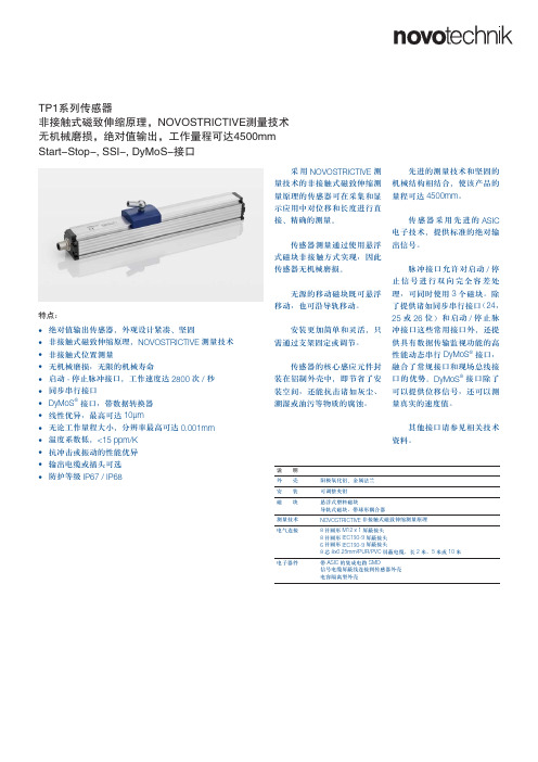
德国Novotechnik 直线位移传感器TP1 总线输出中文资料
up to Umax 7 ( 长久 )
up to Umax 7 ( 长久 )
绝缘阻抗 (500 VDC)
≥ 10
≥ 10
≥ 10
机械参数
尺寸
见图
见图
见图
外壳长度 ( 尺寸 A )
尺寸 B + 146
尺寸 B + 146
尺寸 B + 146
环境参数
工作温度范围
-40 ... +85
-40 ... +85
根据要求可定制产品 标准电缆 10 米 特殊接头 其他分辨率 SSI 双路输出 增量接口,模拟量接口、现场总线 接口 ( 参见对应的技术资料说明 )
重要提示 为避免并行屏蔽电缆电流产生差动 电势,请使用双绞线屏蔽信号电缆。
如有更改,恕不另行通知
TP1系列磁块 非接触式传感器的磁环/磁块
电气零位
电气零位
电气零点公差
± 0.5
± 0.5
± 0.5
输出信号
RS422 脉冲
RS422 绝对 24, 25 或 26 位
RS422 绝对 48 位同步串行
分辨率
标定至 2800 m/ s
1 或 5 µm
5 µm
可重复性
≤6
≤6
≤6
磁感应滞后
≤4
≤4
≤4
工作电压
24 (13 ... 34)
24 (13 ... 34)
其他接口请参见相关技术 资料。
说明 外壳 安装 磁块
测量技术 电气连接
电子器件
阳极氧化铝,金属法兰
可调整夹钳
悬浮式塑料磁块 导轨式磁块,带球形耦合器
NOVOSTRICTIVE 非接触式磁致伸缩测量原理
TURCK BI10-P30-Y1 S100 型号的感应传感器说明书
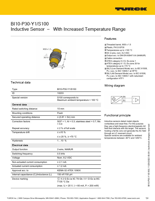
P 30-Y 1/S 100 | 11/29/2022 05-09 | t e c h n i c a l c h a n g e s r e s e r v e dBI10-P30-Y1/S100Inductive Sensor – With Increased Temperature RangeTechnical dataBI10-P30-Y1/S1*******S100 corresponds to:Maximum ambient temperature = 100 °C Rated switching distance 10 mmFlushSecured operating distance ≤ (0.81 × Sn) mmSt37 = 1; Al = 0.3; stainless steel = 0.7; Ms = 0.4≤ 2 % of full scale ≤ ±10 %≤ ± 20 %, ≥ +70 °C1…10 %2-wire, NAMUR 0.5 kHz Nom. 8.2 VDC Non-actuated current consumption ≥ 2.1 mA Actuated current consumption ≤ 1.2 mAKEMA 02 ATEX 1090X )/inductance (L i )150 nF/150 µHÉ II 2 G Ex ia IIC T6 Gb / II 1 D Ex ia IIIC T135 °C DaFeatures■Threaded barrel, M30 x 1.5■Plastic, PA12‐GF30■Temperatures up to +100 °C ■DC 2-wire, nom. 8.2 VDC■Output acc. to DIN EN 60947-5-6 (NAMUR)■Cable connection■ATEX category II 2 G. Ex-zone 1■ATEX category II 1 D, Ex-zone 20 for temperatures up to +70 °C■SIL2 (Low Demand Mode) acc. to IEC 61508,PL c acc. to ISO 13849-1 at HFT0■SIL3 (All Demand Mode) acc. to IEC 61508,PL e acc. to ISO 13849-1 with redundant configuration HTF1Wiring diagramFunctional principleInductive sensors detect metal objectscontactless and wear-free. For this purpose they use a high-frequency electromagnetic AC field that interacts with the target. The sensors hosting a ferrite core coil generate the AC field through an LC resonant circuit.Special versions are available for ambient temperatures between ‐60°C and +250°C.Technical datadevresersegnahclacinhcet|9-5222/92/11|1S/1Y-3PP 30-Y 1/S 100 | 11/29/2022 05-09 | t e c h n i c a l c h a n g e s r e s e r v e d Mounting instructionsAccessoriesQM-306945103Quick-mount bracket with dead-stop;material: Chrome-plated brass. Male thread M36 × 1.5. Note: The switching distance of the proximity switches may change when using quick-mount brackets.BST-30B6947216Mounting clamp for threaded barrel sensors, with dead-stop; material:PA6MW-306945005Mounting bracket for threaded barrelsensors; material: Stainless steel A21.4301 (AISI 304)BSS-306901319Mounting clamp for smooth and threaded barrel sensors; material:PolypropyleneP 30-Y 1/S 100 | 11/29/2022 05-09 | t e c h n i c a l c h a n g e s r e s e r v e dInstructions for useIntended useThis device fulfills Directive 2014/34/EC and is suited for use in areas exposed to explosion hazards according to EN 60079-0:2018 and EN 60079-11:2012.Further it is suited for use in safety-related systems, including SIL2 as per IEC61508.In order to ensure correct operation to the intended purpose it is required to observe the national regulations and directives.For use in explosion hazardous areas conform to classificationII 2 G and II 1 D (Group II, Category 2 G, electrical equipment for gaseous atmospheres and category 1 D, electrical equipment for dust atmospheres).Marking (see device or technical data sheet)É II 2 G and Ex ia IIC T6 Gb and É II 1 D Ex ia IIIC T135 °C Da acc. to EN 60079-0, -11Local admissible ambient temperature -25…+100 °CInstallation/CommissioningThese devices may only be installed, connected and operated by trained and qualified staff. Qualified staff must have knowledge of protection classes, directives and regulations concerning electrical equipment designed for use in explosion hazardous areas.Please verify that the classification and the marking on the device comply with the actual application conditions.This device is only suited for connection to approved Exi circuits according to EN 60079-0 and EN 60079-11. Please observe the maximum admissible electrical values.After connection to other circuits the sensor may no longer beused in Exi installations. When interconnected to (associated) electrical equipment, it is required to perform the "Proof of intrinsic safety" (EN60079-14).Attention! When used in safety systems, all content of the security manual must be observed.Installation and mounting instructionsAvoid static charging of cables and plastic devices. Please only clean the device with a damp cloth. Do not install the device in a dust flow and avoid build-up of dust deposits on the device.If the devices and the cable could be subject to mechanical damage, they must be protected accordingly. They must also be shielded against strong electro-magnetic fields.The pin configuration and the electrical specifications can be taken from the device marking or the technical data sheet.Service/MaintenanceRepairs are not possible. The approval expires if the device is repaired or modified by a person other than the manufacturer. The most important data from the approval are listed.。
NOVOSTRICTIVE Transducer Touchless TM1 牵引传感器说明书

NOVOSTRICTIVETransducerTouchlessTM1Screw flangeCANopenIndustrialSpecial Features• Compact design for tight spaces• Touchless magnetostrictive measurement technology• Operating pressure up to 350 bar, peaks up to 450 bar• Non-contacting position detection with ring-shaped positionmarker• Unlimited mechanical life• No velocity limit for position marker• Absolute output• Outstanding accuracy performance up to 0.04 %• Wide range of supply voltage• Optimized for use in industrial applications• Other configurations see separate data sheetsApplications• Manufacturing Engineering• Level measurement• ActuatorsThe absolute linear transducer TM1 enables a compact and cost-effective position measurement. It consists of a stainless steel flange welded to a pressure-resistant rod and can therefore be used under harsh environmental conditions.The magnetostrictive measuring technology offers excellent accuracy for measuring lengths up to 2000 mm.The passive ring-shaped position marker allows a mechanically decoupled measurement.DescriptionMaterial Flange: SS 1.4307 / AISI 304LFlange cover: AlSiMgBiRod: SS 1.4571 / AISI 316TiSealing: O-ring NBR 90 SH AMounting Screwed via thread M18x1.5Electrical connection Connector M12x1, A-codedMechanical DataDimensions See dimension drawingSpecificationsCAD data seewww.novotechnik.de/en/download/cad-data/Technical DataType TM1-_ _ _ _-306-6_ _-106CANopenMeasured variables Position, speed and temperatureElectrical measuring range (dim. L)0 ... 50 mm up to 0 ... 2000 mmMeasuring range speed25 ... 1000 mm/sProtocol CANopen protocol to CiA DS-301 V4.2.0, Device profile DS-406 V3.2 Encoder Class C2, LSS services to CiA DS-305 V1.1.2 Programmable parameters Position, speed, cams, working areas, temperature, node ID, baud rateNode ID 1 ... 127 (default 127)Baud rate50 ... 1000 kBaudUpdate rate (output) 1 kHz (internal measuring rate 0.5 kHz)Resolution≤ 0.1 mmResolution speed 2 mm/sAbsolute linearity≤ ±0.04 %FS (min. 300 µm)Tolerance of electr. zero point±1 mmRepeatability≤ ±0.1 mmHysteresis≤ ±0.1 mmTemperature error≤ ±15 ppm/K (min. 0.01 mm/K)Supply voltage Ub12/24 VDC (8 ... 34 VDC)Supply voltage ripple≤ 10% UbPower drain w/o load< 1.5 WOvervoltage protection40 VDC (6 s)Polarity protection yes (supply lines and outputs)Short circuit protection yes (all outputs vs. GND and supply voltage)Insulation resistance (500 VDC)≥ 10 MΩBus termination internal w/o (internal load resistance 120 Ω on request)Environmental DataMax. operational speed Mechanically unlimitedVibration IEC 60068-2-620 g, 10 ... 2000 Hz, Amax = 0.75 mmShock IEC 60068-2-27100 g, 11 ms (single hit)Protection class DIN EN 60529IP67Operating temperature-40 ... +105°COperating humidity0 ... 95 % R.H. (no condensation)Working pressure≤ 350 barPressure peaks≤ 450 barBurst pressure> 700 barLife Mechanically unlimitedFunctional safety If you need assistance in using our products in safety-related systems, please contact usMTTF (IEC 60050)391 yearsTraceability Serial number on type labeling: production batch of the sensor assembly and relevant sensor componentsEMC CompatibilityEN 61000-4-2 ESD (contact/air discharge) 4 kV, 8 kVEN 61000-4-3 Electromagnetic fields (RFI)10 V/mEN 61000-4-4 Fast transients (burst) 1 kVEN 61000-4-6 Cond. disturbances (HF fields)10 V eff.EN 55016-2-3 Radiated disturbances Industrial and residential areaFS = Full scale: Signal span according to electrical measuring rangeZ-TH1-P18Ring position marker for fixation with screws M3 Material PA6-GFWeight approx. 12 gOperating temp.-40 ... +100°CSurface pressure max. 40 N/mm²max. 100 NcmFastening torqueof mountingP/N Pack. unit [pcs] 4000056971Z-TH1-P19Z-TH1-PD19 With spacerRing position marker for fixation with screws M4, optionally with or without spacerMaterial PA6-GF, Spacer: POM-GF Weight approx. 14 gOperating temp.-40 ... +100°CSurface pressure max. 40 N/mm²Fastening torque max. 100 NcmP/N Spacer Pack. unit[pcs] 400005698-1 400107117incl.1Z-TH1-P30Ring position marker for mounting via lock washer and retaining ringMaterial NdFeB bonded (EP)Weight approx. 5 gOperating temp.-40 ... +100°CSurface pressure max. 10 N/mm²P/N Pack. unit [pcs] 4001061391Z-TH1-P25U-shaped position marker for fixation with M4 screwsCaution: for dimension of electrical zero point please follow the user manual!Material PA6-GFOperating temp.-40 ... +105°CSurface pressure max. 40 N/mm²Fastening torquemax. 100 Ncmof mountingP/N Pack. unit [pcs] 4001050761Z-TH1-P32Ball-type floating position markerMaterial SS 1.4571 / AISI 316Ti Weight approx. 42 gOperating temp.-40 ... +100°C≤ 40 barCompressionstrengthDensity720 kg/m³Immersion depth36.7 mmin waterP/N Pack. unit [pcs] 4001057031Z-TH1-P21Cylinder floating position markerMaterial SS 1.4404 / AISI 316L Weight approx. 20 gOperating temp.-40 ... +100°C Compression≤ 8 barstrengthDensity740 kg/m³approx. 26.6 mm Immersion depthin waterP/N Pack. unit [pcs] 4000560441Floating Position Marker - Installation RecommendationWhen using floating position markers, we recommend to secure the marker against loss with a washer at the rod end.For this purpose, a sensor version with inner thread at the rod end is required (s. ordering code).Z-TH1-M01Lock nut ISO 8675, M18x1.5-A2P/N Pack. unit [pcs] 4000560901Connector SystemM12EEM-33-49/50/51M12x1 Mating female connector, 5-pin, straight, A-coded, with molded cable,IP67, shielded (shield on knurl), open ended Plug housing TPUCable sheath PUR, Ø = 6.7 mm,-25 ... +90°C (socket)-20 ... +80°C (cable)Lead wires PE, 2x0.25 mm²+2x0.34 mm²P/N Type Length 400106368EEM-33-49 2 m 400106371EEM-33-50 5 m 400106372EEM-33-5110 mEEM-33-52M12x1 Mating female/male connector, 5-pin, straight, A-coded, with molded cable,IP67, shielded (shield on knurl), CAN-BusPlug housing PURCable sheath PUR, Ø = 6.7 mm,-25 ... +90°C (plug/socket)-20 ... +80°C (cable)Lead wires PE, 2x0.25 mm²+2x0.34 mm²P/N Type Length 400106373EEM-33-52 5 mEEM-33-45M12x1 splitter / T-connector, 5-pin,A-coded, IP68,1:1 connection,female - male - female, CAN-BusPlug housing PUR, -25 ... +85°CP/N Type400056145EEM-33-45EEM-33-47M12x1 terminating resistor, 5-pin, A-coded,IP67, 120 Ω resistance, CAN-BusPlug housing PUR, -25 ... +85°CP/N Type400056147EEM-33-47Novotechnik U.S., Inc.155 Northboro RoadSouthborough, MA 01772Phone 508 485 2244Fax 508 485 2430********************© Jul 18, 2022The specifications contained in our datasheets are intended solely for informational purposes. The documented specification values are based on ideal operational and environmental conditions and can vary significantly depending on the actual customer application. Using our products at or close to one or more of the specified performance ranges can lead to limitations regarding other performance parameters. It is therefore necessary that the end user verifies relevant performance parameters in the intended application. We reserve the right to change product specifications without notice.。
VibroOne 激光速度测量仪器产品介绍说明书
The Polytec VibroOne laser Doppler vibrometeris the one-box solution for non-contact vibrationmeasurement. With VibroOne you analyze acoustics,dynamics and vibration issues in both R&D andindustrial quality control with laser precision. TheVibroOne comprises an all-in-one front-end withintegrated laser and a fiber-coupled, compact sensorhead. Integrated with the VibroLink digital interface andthe VibSoft data acquisition and analysis software, thisvibration measurement system is ready to point, shootand measure in an instant. VibroOne One-box solution for laser vibration sensing Preliminary datasheetVibroOne is specifically designed for tightly packed setups, whether in research laboratories, challenging production environments or for non-contact analysis of tiny details on microstructures or biomedical probes. The optional inline HD+ camera helps positioning the laser precisely and provides proper test documentation. An optical filter adjusts for a perfect contrast. Optional microscope lenses focus to a 1.5 μm laser spot, allowing the inspection of fine details.Highlights■Non-contact measurement ofvibration with laser precision■Compact design for simplehandling in labs and production■Easy setup and documentationwith integrated HD+ camera■From DC to 3 MHz with highesttime resolution■Synchronous output of displace-ment, velocity and acceleration■VibroLink digital interface forconvenient setup, data transferand best SNRTechnical data 1 Depending on configuration21 Height of front-end housing with sensor tray and cord wrap: 166 mm (6.54 in)2 For weight of 3 m fiber cable add 300 g (0.66 lbs), for 5 m fiber cable add ca. 600 g (1.3 lbs)31 Measured from the front edge of the front lens1 Measured from the front edge of the front lens (respectively from the front of the microscope objective).2 with VIB-A-20xLENS microscope objective3 with VIB-A-10xLENS microscope objectiveConfigurable optionsThe VibroOne Laser Vibrometer offers a lot of flexibility: thanks to its various options for frequency bandwidth,output signals for measurands (velocity, displacement and acceleration), signal enhancement capabilities andaccessories, which can be combined freely with each other, it fits perfectly to your application.Frequency bandwidthChoose between different maximum frequency bandwidths from 100 kHz to 3 MHz covering the acoustic andthe ultrasonic range.S = Standard / O = OptionVelocity outputVibroOne allows measuring vibrational velocities up to ± 12 m/s (see also page 9). For extending the velocityresolution, the option VIO-VelResS offers additional measurement ranges down to ± 1 mm/s (peak).S = Standard / O = OptionS = Standard / O = Option4Displacement outputIn addition to the velocity output, the displacement output option VIO-DispOut can be added, providing amaximum displacement of ± 200 mm (peak). For resolving smallest movements, super fine measurement rangescan be chosen (see also page 10).S = Standard / O = OptionS = Standard / O = OptionAcceleration outputAdding the acceleration output option VIO-AccOut enables measuring accelerations up to 100x106 m/s2at frequencies up to 3 MHz (see also page 12). Recommended for measuring frequencies up to 100 kHz.Signal enhancementFor reliable measurement results with best signal-to-noise ratio even under difficult conditions, the included trackingfilter with three ranges is available.S = Standard56Options and accessoriesSensor head options S = Standard / O = Option8VibSoft data acquisition and analysis software VibSoft is a comprehensive and easy-to-use software package for digital vibration data acquisition and analysis. VibSoft closes the gap between raw signal acquisition and profound analysis of vibration measurement data. The VibroLink interface allows direct and fully digital data acquisition of the velocity signal via Ethernet for the full frequency bandwidth. Alternatively, the multi-channel DAQ units permit connecting additional analog inputs like other sensors, processing data up to 40 MHz. Further options like the powerful SignalProcessor (a Polytec math library for post-processing) and a scripting engine for individual post-processing and control make VibSoft an extremely powerful tool.Polytec offers a wide range of accessories for setting up and performing measurements. Please contact your local vibrometer sales engineer or visit our website /vibroone for more detailed information.Options and accessoriesS = Standard / O = OptionVelocity performance specificationsS = Standard / O = OptionMaximum linearity error: 0.5% for all measurement ranges.1 Frequency range from 0 Hz to the given value. Maximum frequency bandwidth depending on system configuration.2 The noise-limited resolution is defined as the signal amplitude (rms) at which the signal-to-noise ratio is 0 dB and with 1 Hz spectral resolution.3 Requires option VIO-VelResS4 Standard: included with configuration VIO-VEL-12m/s and VIO-VelResH.The signal delay is independent of the selected measurement range and the switched on filters.It is identical for velocity, displacement and acceleration.9Displacement performance specifications 11 Displacement output requires option VIO-DispOut2 Frequency range from 0 Hz to the given value. Maximum frequency bandwidth depending on system configuration.3T he resolution corresponds to the quantization step at the analog output. Noise limited resolution: < 30 fm/SQRT(Hz) in the smallest measurement range.The noise-limited resolution is defined as the signal amplitude (rms) at which the signal-to-noise ratio is 0 dB with an 1 Hz spectral resolution.10Dimensions7263183659free space min. 1505459SensorAll dimensions in mm if not marked otherwiseVIO-I-130-STAVIO-I-130-CAMA = total height VIO-I-130-CAM B= total height VIO-I-130-STAAB216141Ø 366764"X"8067303042.542.5Ø 4 F84 F 8"X"11。
角位移传感器使用说明书【免费下载】
大家知道角位移传感器是什么吗?很多人看到这个名词的第一反应是皱皱眉吧。
今天小编调查了资料跑来告诉大家一些最基本的情况,角位传感器究竟是什么呢,如何操作呢?对我们又有什么作用呢?下面就让我们带着问题看看角位移传感器的操作指南、基本原理及其应用吧。
角位移传感器操作指南:1、以传感器安装凸台定位,用螺钉、螺母或压板固紧在金属板上。
在安装传感器时,严禁对轴、壳体进行车、钻等加工,避免轴或壳体受到外界的冲击力和压力,轴的轴向和径向不允许受到冲击力和压力(静压力应小于300n)。
严禁松动传感器上的螺钉,转动固紧环位置。
2、传感器出轴与其它机件联接时应注意轴心线要保持在一直线上(包括工作状态),如轴心线有偏差存在,建议使用万向接头或波纹管等转接件,以免传感器出轴弯曲变形,损坏其他器件,从而影响使用。
3、应防止水滴、蒸气、溶剂和腐蚀性气体对传感器的侵袭,防止金属屑或其他粉末进入传感器。
4、传感器的外部接线应焊接在引出端的腰槽处,尽量不要焊在引出端的顶部。
焊接时应使用不大于45w电铬铁,焊接时间应小于5秒。
在焊接及未冷却透时不应拉动导线,以免电刷丝或整个引出端被拉出,甚至脱落。
焊接时尽量少用焊剂、焊油,时间要短,避免焊剂蒸气通过引出端进入传感器内部,导致蒸气冷却后沉积在电阻元件表面,造成等效噪声电阻变差,甚至开路。
角位移传感器基本原理:角度位移传感器原理角度传感器用来检测角度的。
它的身体中有一个孔,可以配合乐高的轴。
当连结到RCX 上时,轴每转过1/16圈,角度传感器就会计数一次。
往一个方向转动时,计数增加,转动方向改变时,计数减少。
计数与角度传感器的初始位置有关。
当初始化角度传感器时,它的计数值被设置为0,如果需要,你可以用编程把它重新复位。
角度位移传感器实例如果把角度传感器连接到马达和轮子之间的任何一根传动轴上,必须将正确的传动比算入所读的数据。
举一个有关计算的例子。
在你的机器人身上,马达以3:1的传动比与主轮连接。
德国NOVOtechnik直线位移传感器TR-TRS系列说明书
可选辅件 4 个 Z3-31 安装夹 产品编号:059010
直接头,IEC130-9, 5x0.75mm2,Ø 4-6 mm EEM 33-70,不带屏蔽,IP67 EEM 33-71,带屏蔽,IP40
注意事项 在数据表中所列的线性度、使 用寿命、微线性度、抗外干扰 阻值和分压形式的温度系数等 数值,是传感器工作在以运算 放大器作为电压输出器输出电 压给滑刷,且滑刷上不带负载 (le ≤ 1 µA) 的条件得出的。
± 1 mm ± 1.5 mm
g g g N N N Hz Ncm
℃ Hz mm g g ms 次
交货内容包括 2 个 Z-45 安装夹,包含: 4 个 M4x10 螺钉 1 个压入式硬金属触点
推荐辅件 过程控制显示器 MAP ... 信号转换器 MUP ... / MUK ..., 工作电压 24V,标准信号输出
TR/TRS 系列传感器 直线位移传感器,工作量程达 100 mm 带复位弹簧
说明 外壳 安装 拉杆 测量触点 柔性轴承 电阻元件 滑刷组件 电气连接 TR 系列 TRS 系列
型号
TR-0010
TR-0025 TRS-0025
TR-0050 TRS-0050
TR-0075 TRS-0075
TR-0100 TRS-0100
抗振动标准
寿命 防护等级
TR-0010
TR-0025 TRS-0025
10
25
12
27
1
1
20
0.25
0.2
0.002
≤1
10
24
42
通常 5
≥ 10
≤ 100
48 15 7 6
80
18 ≤ 3.5 ≤ 5.0 最大 5 20 140
激光位移传感器操作手册说明书
激光位移传感器操作手册V3.0目录第1章:产品概要......................................................................... 1-11.1 包装内容 ......................................................................................... 1-11.2 各部件名称及功能........................................................................... 1-21.3 安装................................................................................................. 1-3 第2章:设定与测量 ..................................................................... 2-1 第3章:软件操作......................................................................... 3-13.1 通信设置 ......................................................................................... 3-13.2 位置读取与归零设定 ....................................................................... 3-2 第4章:通讯指令......................................................................... 4-14.1 通讯参数列表 .................................................................................. 4-14.2 通讯协议 ......................................................................................... 4-4 第5章:产品规格......................................................................... 5-1 第6章:安全注意事项.................................................................. 6-1 第7章:保固 ................................................................................ 7-1版本更新历程激光位移计操作手册V3.0版本更新历程版本更新日期V1.0 第一版发行2018/09/03V2.0 新增「反应速度设定」与「中值滤波器设定」功能说明与通讯地址设定方式。