Syllabus BIOS 419 07-08
IBM zSeries处理器容量参考(zPCR)简介说明书

Enter LPAR Definitions for the 2064-210
© 2005 IBM Corporation
ATS - Washington Systems Center
Select Return
© 2005 IBM Corporation
ATS - Washington Systems Center
© 2005 IBM Corporation
ATS - Washington Systems Center
What is zPCR
A Java based PC tool Provides the capacity relationship of zSeries processors
– LSPR workloads determine the capacity ratio – Includes impact of LPAR configurations – Expected accuracy of + or – 5%
Select Choosing Workload Mix
© 2005 IBM Corporation
ATS - Washington Systems Center
Select LoIO-Mix
© 2005 IBM Corporation
ATS - Washington Systems Center
Advanced Technical Support – Washington Systems Center
An Introduction to the IBM Processor Capacity Reference for zSeries
Walt Caprice IBM Washington Systems Center
阿尔法拉瓦尔S分离器系统805 815 817清洁系统汇编说明书

IntroductionAlfa Laval’s S Flex separation systems combine the high efficiency, low sludge output and low operating cost of Alfa Laval centrifugal separators with a flexible scope of supply. Extensive possibilities for the separation system layout and assembly make it possible to suit any engine room and any oil separation application.In addition, S Flex separation systems feature the EPC 60 controller, which enables the easy navigation of menus, parameters and alarms. The EPC 60 controller also has a modular construction for easy I/O board addition and replacement.The S Flex separation concept includes the complete S separator range. Separators of different sizes can be combined into one module, including both fuel and lube cleaning, even within a single customer specified module.ApplicationS separators are based on Alcap technology, which means they detect when the oil/water interphase moves into the disc stack and automatically activates the drain or discharge mechanism and thereby maintain best possible performance at all times. This makes them particularly suitable for separating fuels and oils with varying density and viscosity, though they can be used to clean all of the following:•Residual fuels•Distillate fuels•Biofuels•Lubricating oilsS separators efficiently clean distillate and residual fuels according to ISO 8217, including ultra-low, very-low and high sulphur fuel oils (ULSFO, VLSFO and HSFO) with densities upto 1 010 kg/m3 at 15°C and viscosities up to 700 cSt at50°C.The S separator is optimized to clean biofuels according to EN15940 (HVO) and EN14214/ASTM D6751 (FAME).For treatment of other fuel types please consult your local Alfa Laval office.S separators are designed for automatic operation in periodically unmanned engine rooms at sea and in power stations ashore.Benefits•Small footprint, high flexibility — The small separator and the modular nature of the surrounding components allow easy installation and flexible positioning in the engine room.•Alcap technology — A water transducer in the clean oiloutlet automatically adjusts the oil/water interphase todifferent fuel densities and viscosities, and hencemaximizes separation performance.•High separation efficiency — An optimized design ensures the best possible separation efficiency from the bowl and disc stack.•Simple installation — No tank is needed to supplyoperating water and no pipe is needed to discharge it,which further simplifies installation.•Separate feed pump — A separate feed pump reducespipe-work to and from the preheater.•Low oil loss — The separator’s highly efficientdisplacement ensures that virtually no oil is lost.•Efficient discharge — Separated sludge and water areefficiently removed from the system.•Easy operation and service — The PLC based EPC 60controller is designed for “one-button” starts and stops, as well as intuitive menu navigation. Information aboutparameters and alarms can be easily accessed, whichsimplifies both operation and troubleshooting. The EPC 60 also has a modular construction that enables fastertroubleshooting and I/O board replacement.•Remote control and monitoring — Using either Ethernet or Bus communication, Flex systems and modules based on S Separators 805/815/817 can be controlled andsupervised remotely from the control room. A variety ofalarm functions is available as standard and extra I/Oboards can be added to the EPC 60 controller in order to enhance its monitoring capabilities.DesignSingle Flex module with separator (excluding heater and pump)The S Flex separation concept provides a wide range of alternatives for S separators. Depending on the need, an S separator can be supplied as a separator and ancillaries, as a customer-specified module, or as part of a comprehensive package including services and order-specific documentation.Flex systemAn S separator with ancillaries in the form of optimized block components provides full say over the use of space. This allows for local modularization or do-it-yourself assembly. Flex modulesA compact S separator module can be built to a customer-specified configuration from a wide range of modular skids and machine blocks. Multi-modules are possible, as well as mixed modules including one or more S separators and/or P separators for the simultaneous treatment of different types of mineral oils. All Flex modules are factory tested to ensure faster start-up and commissioning.Scope of supplyA preventive maintenance programme using Alfa Laval Service Kits ensures safe and easy maintenance.•Recommended maintenance intervals:–Intermediate Service every 2000 h or 3 months–Major Service every 8000 operating hours or 12months•Service kits contain all necessary spare parts for each service and tips for maintenance at regular intervals:–Intermediate Service Kit with O-rings and seals for separator bowl, inlet and outlet.–Major Service Kit with parts for drive system, belt,bearings and friction pads.•The System Manual includes detailed information in electronic or printed form:–Installation instructions –Operating instructions–Alarms and troubleshooting –Service and spare parts•Commissioning and technical services, including startup assistance and advice on operation and maintenance, are available from all Alfa Laval offices.•Training in all aspects of oil treatment, freshwater generation and heat transfer is available.•All services can be incorporated into specifically tailored Nonstop Performance packages. Details are available from local Alfa Laval offices.Options1.ALP feed pump with IE3 motor2.HEATPAC CBM heater3.HEATPAC EHM heater4.S&T Heat exchangerFlex separation systems based on S separators 805/815/817can be complemented with the following equipment:•Starter (included in module versions)•Heatpac heaters •Space heating•Additional thermometers •Vibration switch •ALP feed pump •Strainer•Flow regulating system •Sludge removal kit•Sludge outlet butterfly valve kit •Steam shut-off valve kit •Air pressure reducer valve•Pipe arrangement for multiple modules, including heater cross-connection•Emergency safety shutdown •Remote monitoringWorking principle12346571.Untreated oil2.Clean oil3.Paring disc4.Gravity disc5.Disc stack6.Seal ring7.Discharge portThe S Flex separation systems based on S separators 805/815/817 are operated automatically by the EPC 60controller, except at startup of the separator. Untreated oil,heated to the correct temperature, is fed continuously to the separator. The separator is driven by an electric motor via a friction clutch and belt.The separator bowl is fixed at the top of a spindle, which is supported by bearings and special composite springs. This bowl can be arranged as a purifier or as a clarifier. Bothconfigurations remove sludge, which accumulates at the bowl periphery and is intermittently discharged.In a purifier configuration, both sludge and water are separated from the oil, which means that water iscontinuously discharged from the bowl. The EPC 60 controller automatically controls the admission of water for the water seal and the displacement of oil prior to sludge discharge, but a gravity disc is needed to establish the correct interphase position in the separator bowl, i.e. the boundary between the oil and the water seal. The size of the gravity disc must be matched to the oil’s density, viscosity/temperature and feed rate to the separator.In a clarifier configuration, a clarifier disc is fitted instead of a gravity disc. The water outlet is blocked, which means that the separator’s water-handling capacity is limited and that water accumulates like sludge.During normal operation, vital process parameters aremonitored. These parameters, as well as alarms, are indicated by easy-to-understand text messages on the LCD display of the EPC 60 controller.The EPC 60 controller provides many alarm functions,including alarms for low oil pressure, high sludge tank level (if the optional sludge removal kit is included) and power failure.Additional functions are available for a vibration alarm when the optional vibration switch is fitted.11651.Untreated oil inlet2.Oil return3.Water inlet (C1 = Conditioning water, C2 = Opening water,C3 = Closing water)4.Clean oil outlet5.Sludge and water outlet6.Optional7.Feed pump8.Heater9.Pneumatically controlled change-over valve 10.Pressure transmitter, oil 11.Control unit12.Pressure transmitter, oil 13.Water transducer 14.Regulating valve15.Solenoid valve block, waterTechnical dataMax. recommended capacity, l/h HFO 380 cSt/50˚CControl voltage 1–phase, 100/110/115/230 V Frequency 50 or 60 HzControl airMin 5 bar, max 8 bar Operating water pressureMin 2 bar, max 8 barDimensional drawingS 8051650 x 1200 x 110025610S 8151650 x 1200 x 110025610S 8171650 x 1200 x 1100256101 Including ALP feed pump, CBM heater and SRKThis document and its contents are subject to copyrights and other intellectual property rights owned by Alfa Laval AB (publ) or any of its affiliates (jointly “Alfa Laval”). No part of this document may be copied, re-produced or transmitted in any form or by any means, or for any purpose, without Alfa Laval’s prior express written permission. Information and services provided in this document are made as a benefit and service to the user, and no representations or warranties are made about the accuracy or suitability of this information and these services for any purpose. All rights are reserved.200006733-3-EN-GB© Alfa Laval How to contact Alfa LavalUp-to-date Alfa Laval contact details for all countries are always availableon our website at 。
戴尔精密工作站Wyse快速入门指南说明书
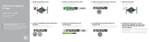
1Install the system into a rackInstallez le système dans un rackInstale el sistema en un rack2Connect the keyboard, mouse, and monitor(optional)Connectez le clavier, la souris et le moniteur (facultatif)Conecte el teclado, el ratón y el monitor (opcional)3Connect the GPUs to the host cardsConnectez les GPU aux cartes hôteConecte las GPU a las tarjetas de host4Connect the network ports to anexternal switchConnectez les ports réseau à un commutateur externeConecte los puertos de red al conmutador externo8Download the Quick Start Tool andDell Precision Appliance for Wyse User’sGuide for Dell Precision Rack 7910 from/supportPour Dell Precision Rack 7910, téléchargez l’outil de démarrage rapideet le guide d’utilisation de Dell Precision Appliance pour Wyse à partirdu site /supportDescargue Quick Start Tool y Dell Precision Appliance para la Guía deusuario de Wyse para Dell Precision Rack 7910 en /support5Connect the system to an electrical outletConnectez le système à une prise électriqueConecte el sistema a una toma de alimentación eléctrica6Loop and secure the power cable in theretention clipFormez une boucle et fixez le câble d’alimentation au clip de maintienEnrolle y fije el cable de alimentación con el gancho de retención7Power on the systemMettez le système sous tensionEncienda el sistema1. Power button/Power light2. Non-maskable interrupt(NMI) button 3. System identification button 4. VGA connector 5. LCD menu buttons6. Information tag7. LCD panel8. Hard drives9. vFlash media card slot 10. USB 2.0 connector 11. USB management port/iDRAC Direct 12. Optical drive (optional)13. System identification button 14. System identification connector15. iDRAC8 Enterprise port (optional)16. Host Card (optional)17. Serial connector 18. VGA connector 19. USB 3.0 connectors 20. Quadro GPU (optional)21. Network connectors 22. Power supply1. Bouton d’alimentation/Voyantd’alimentation 2. Bouton d’interruption nonmasquable (NMI)3. Bouton d’identification du système 4. Port VGA5. Boutons de menu de l’écrand’affichage LCD 6. Étiquette d’informations 7. Écran d’affichage LCD 8. Disques durs9. Logement pour cartemémoire vFlash 10. Port USB 2.011. Port de gestion USB/iDRAC Direct 12. Lecteur optique (en option)13. Bouton d’identification du système 14. Port d’identification du système 15. Port iDRAC8 Enterprise (en option)16. Carte hôte (en option)17. Port série 18. Port VGA 19. Ports USB 3.020. GPU Quadro (en option)21. Ports réseau 22. Alimentation1. Botón de alimentación/indicadorde alimentación 2. Botón de interrupción noenmascarable (NMI)3. Botón de identificación del sistema4. Conector VGA5. Botones del menú de lapantalla LCD 6. Etiqueta informativa 7. Panel de la pantalla LCD 8. Unidades de disco duro 9. Ranura de la tarjeta demedios vFlash 10. Conector USB 2.011. Puerto de gestión USB/DirectoiDRAC 12. Unidad óptica (opcional)13. Botón de identificación del sistema 14. Conector de identificacióndel sistema 15. Puerto iDRAC8 Enterprise(opcional)16. Tarjeta de host (opcional)17. Conector serie 18. Conector VGA 19. Conectores USB 3.020. GPU Quadro (opcional)21. Conectores de red 22. Fuente de alimentaciónFeaturesCaractéristiques | FuncionesProduct support and manuals Support produits et manuelsManuales y soporte técnico de productos /support/support/manualsContact Dell Contacter DellPóngase en contacto con Dell /contactdellRegulatory and safetyRéglementations et sécuritéNormativa y seguridad /regulatory_complianceRegulatory model Modèle réglementaire Modelo normativo E31SRegulatory type Type réglementaire Tipo normativo E31S001Computer modelModèle de l’ordinateur Modelo de equipoDell Precision Appliance for Wyse© 2015 Dell Inc.Printed in China.2015-03Información para NOM, o Norma Oficial MexicanaLa información que se proporciona a continuación se mostrará en los dispositivos que se describen en este documento, en conformidad con los requisitos de la Norma Oficial Mexicana (NOM):Importador:Dell México S.A. de C.V.Paseo de la Reforma 2620 - Piso 11.° Col. Lomas Altas 11950 México, D.F.Número de modelo reglamentario:E31SVoltaje de entrada:100 V CA–240 V CA / 200 V CA–240 V CA /48-60 VDCCorriente de entrada (máxima):12 A–6,5 A (x2) / 10 A–5 A (x2) / 6,5 A–3 A (x2) /5 A (x2) / 32 A (x2)Frecuencia de entrada:50 Hz–60 Hzpour de plus amples informations sur la configuration du GPUPara obtener más información acerca de la configuración de la GPU。
ARIES ARIES-P -Ver.04- 8 0 2 7 9 0 8 1 1 3 7 4 0 产

ISTRUZIONI D'USO E DI INSTALLAZIONE INSTALLATION AND USER'S MANUALINSTRUCTIONS D'UTILISATION ET D'INSTALLATION INSTALLATIONS-UND GEBRAUCHSANLEITUNG INSTRUCCIONES DE USO Y DE INSTALACION INSTRUÇÕES DE USO E DE INSTALAÇÃOCENTRALINA DI COMANDO D811184A ver. 04 08-02-02I CONTROL UNIT GB UNITÉ DE COMMANDE F STEUERZENTRALE D CENTRAL DE MANDO E CENTRAL DO MANDOP ARIES - ARIES P8027908113740a“WARNINGS” leaflet and an “INSTRUCTION MANUAL”.These should both be read carefully as they provide important information about safety, installation, operation and maintenance. This product complies with the recognised technical standards and safety regulations. We declare that this product is in conformity with the following European Directives: 89/336/EEC and 73/23/EEC (and subsequent amendments).1) GENERAL OUTLINEThe ARIES control unit has been designed for swing gates. It can be used for one or two gate controllers.The control unit mod. ARIES P can also be used to perform opening of a single actuator while keeping the other one closed (pedestrian access).2) FUNCTIONSSTOP: In all cases: it stops the gate until a new start command is given.PHOT:Functions can be set with Dip-Switch.Activated during closing.Activated during opening and closing.Rapid closingON: When the position of the gate photocells is exceeded, during both opening and closing, the gate automatically starts to close even if TCA is activated. We recommend setting DIP3 to ON (photocells only activated during closing).Blocks impulsesON: During opening, START commands are not accepted.OFF: During opening, START commands are accepted.PhotocellsON: Photocells only activated during closing.OFF: Photocells activated during opening and closing.Automatic closing time (TCA)ON: Automatic closing activated (can be adjusted from 0 to 90s)Preallarm (mod. ARIES P only)ON: The flashing light turns on abt 3 seconds before the motors start.FOR THE INSTALLER: check the boxes you are interested in.START:four-step logic Gate closedGate openDuring openingDuring closingAfter stop START: two-step logic SCA: Gate open indicating lightit opens it opensit stops and activates TCAit closesit stops and does not activate TCAit starts opening it stops and activats TCA (if activated)it closesit opensit opensoffononflashingATTENTION:Dip non used in mod. ARIES (always in OFF set).3) MAINTENANCE AND DEMOLITIONThe maintenance of the system should only be carried out by qualified personnel regularly. The materials making up the set and its packing must be disposed of according to the regulations in force.Batteries must be properly disposed of.WARNINGSCorrect controller operation is only ensured when the data contained in the present manual are observed. The company is not to be held responsible for any damage resulting from failure to observe the installation standards and the instructions contained in the present manual.The descriptions and illustrations contained in the present manual are not binding. The Company reserves the right to make any alterations deemed appropriate for the technical, manufacturing and commercial improvement of the product, while leaving the essential product features unchanged, at any time and without undertaking to update the present publication.D 811184A _04Thank you for buying this product, our company is sure that you will be more than satisfied with the product ’s performance. The product is supplied with a “WARNINGS ” leaflet and an “INSTRUCTION MANUAL ”.These should both be read carefully as they provide important information about safety, installation, operation and maintenance.This product complies with the recognised technical standards and safety regulations. We declare that this product is in conformity with the following European Directives: 89/336/EEC and 73/23/EEC (and subsequent amendments).1) GENERAL OUTLINEThe ARIES control unit has been designed for swing gates. It can be used for one or two gate controllers.The control unit mod. ARIES P can also be used to perform opening of a single actuator while keeping the other one closed (pedestrian access).2) GENERAL SAFETYWARNING! An incorrect installation or improper use of the product can cause damage to persons, animals or things.•The “Warnings ” leaflet and “Instruction booklet ” supplied with this product should be read carefully as they provide important information about safety, installation, use and maintenance.•Scrap packing materials (plastic, cardboard, polystyrene etc) according to the provisions set out by current standards. Keep nylon or polystyrene bags out of children ’s reach.•Keep the instructions together with the technical brochure for future reference.•This product was exclusively designed and manufactured for the use specified in the present documentation. Any other use not specified in this documentation could damage the product and be dangerous.•The Company declines all responsibility for any consequences resulting from improper use of the product, or use which is different from that expected and specified in the present documentation.•Do not install the product in explosive atmosphere.•The Company declines all responsibility for any consequences resulting from failure to observe Good Technical Practice when constructing closing structures (door, gates etc.), as well as from any deformation which might occur during use.•The installation must comply with the provisions set out by the following European Directives: 89/336/EEC, 73/23/EEC, 98/37/ECC and subsequent amendments.•Disconnect the electrical power supply before carrying out any work on the installation. Also disconnect any buffer batteries, if fitted.•Fit an omnipolar or magnetothermal switch on the mains power supply,having a contact opening distance equal to or greater than 3mm.•Check that a differential switch with a 0.03A threshold is fitted just before the power supply mains.•Check that earthing is carried out correctly: connect all metal parts for closure (doors, gates etc.) and all system components provided with an earth terminal.•The Company declines all responsibility with respect to the automation safety and correct operation when other manufacturers ’ components are used.•Only use original parts for any maintenance or repair operation.•Do not modify the automation components, unless explicitly authorised by the company.•Instruct the product user about the control systems provided and the manual opening operation in case of emergency.•Do not allow persons or children to remain in the automation operation area.•Keep radio control or other control devices out of children ’s reach, in order to avoid unintentional automation activation.•The user must avoid any attempt to carry out work or repair on the automation system, and always request the assistance of qualified personnel.•Anything which is not expressly provided for in the present instructions,is not allowed.3) TECHNICAL SPECIFICATIONSPower supply:...............................................................230V ±10% 50Hz Absorption on empty:.................................................................0.5A max Output power for accessories:..........................................24V~ 6VA max Max relay current:................................................................................8A Max power of motors:...............................................................300 W x 2Torque limiter:.................................................Self-transformer with 4 pos Limit switch:................................................................Adjustable run timePanel dimensions:.........................................................................See fig.1Cabinet protection:............................................................................IP55Working temperature:...............................................................-20 +55°C 4) TERMINAL BOARD CONNECTIONS(Fig.2)CAUTION: Keep the low voltage connections completely separated from the power supply connections.Fig.3 shows the fixing and connection method of the drive condensers whenever they are not fitted to the motor.JP51-2 Single-phase power supply 230V ±10%, 50 Hz (1=L/2=N).For connection to the mains use a multiple-pole cable with a minimum cross section of 3x1.5mm 2 of the type indicated in the above-mentioned standard (by way of example, if the cable is not shielded it must be at least equivalent to H07 RN-F while, if shielded, it must be at least equivalent to H05 VV-F with a cross section of 3x1.5mm 2).JP33-4 (mod.ARIES-P) 230V 40W max. blinker connection.5-6 (mod.ARIES) 230V 40W max. blinker connection.7-8-9 Motor M1 connection - 8 common, 7-9 start.10-11-12 Motor M2(r) connection - 11 common, 10-12 start.JP413-14 Open-close button and key switch (N.O.).13-15 Stop button (N.C.). If unused, leave bridged.13-16 Photocell or pneumatic edge input (N.C.). If unused, leave bridged.17-18 24V 3W max. gate open warning light.18-19 24V~ 0.25A max. (6VA) output (for supplying photocell or other device).20-21 Antenna input for radio-receiver board (20 signal - 21 braid).22 Common terminal (equivalent to terminal 13).23 Terminal for pedestrian control. It moves the leaf of motor M2 connected to terminal 10-11-12. This terminal is available only in ARIES-P control unit.JP225-26 2nd radio channel output of the double-channel receiver board (terminals not fitted on ARIES but fitted on ARIES-P) contact N.O.JP1 Radio-receiver board connector 1-2 channels.5) FUNCTIONSDL1:Power-on LedIt is switched on when the board is electrically powered.START: four-step logic: (DIP5 OFF)gate closed:..................................................................................it opens during opening:............................................... it stops and activates TCA gate open:................................................................................... it closes during closing:.................................... it stops and does not activate TCA after stop:.........................................................................it starts opening START: two-step logic: (DIP5 ON)gate closed:..................................................................................it opens during opening:................................it stops and activats TCA (if activated)gate open:....................................................................................it closes during closing:..............................................................................it opens after stop:.....................................................................................it opens STOP: In all cases: it stops the gate until a new start command is given.PHOT:Functions can be set with DIP-SWITCH.Activated during closing if DIP3-ON.Activated during opening and closing if DIP3-OFF.SCA: Gate open indicating light.with gate closed:...................................................................................off when gate is opening:...........................................................................on with gate open:.......................................................................................on when gate is closing:.....................................................................flashing 6) DIP-SWITCH SELECTION DIP1 Rapid closingON: When the position of the gate photocells is exceeded, during both opening and closing, the gate automatically starts to close even if TCA is activated. We recommend setting DIP3 to ON (photocells only activated during closing).OFF: Function not activated.DIP2 Blocks impulsesON: During opening, START commands are not accepted.OFF: During opening, START commands are accepted.DIP3 PhotocellsON: Photocells only activated during closing.OFF: Photocells activated during opening and closing.D 811184A _04DIP4 Automatic closing time (TCA)ON: Automatic closing activated (can be adjusted from 0 to 90s).OFF: Automatic closing not activated.DIP5 Control logicON: 2-step logic is activated (see start paragraph).OFF: 4-step logic is activated (see start paragraph).DIP6: Preallarm (mod.ARIES P only)ON: The flashing light turns on abt 3 seconds before the motors start.OFF The flashing light turns on simultaneously with the start of the motors.ATTENTION:Dip non used in mod. ARIES (always in OFF set).7) TRIMMER ADJUSTMENTTCA This adjusts the automatic closing time, after which time the gate automatically closes (can be adjusted from 0 to 90s).TW This adjusts the motor working time, after which time the motor stops (can be adjusted from 0 to 40s).TDELAY This adjusts the closing delay time of the second motor (M2).8) MOTOR TORQUE ADJUSTMENTThe ARIES control unit has electric torque adjustment which allows the motor force to be adjusted.The adjustment should be set for the minimum force required to carry out the opening and closing strokes completely.Adjustment is carried out by moving the connection 55 (fig.3) on the tran-sformer sockets as described below:Pos.T1 1st TORQUE (MINIMUM TORQUE)Pos.T2 2nd TORQUE Pos.T3 3rd TORQUEPos.T4 4th TORQUE (MAXIMUM TORQUE)4 motor torque values can be obtained.To gain access to the torque adjustment sockets, disconnect the mains supply and remove the protective case “P ” of the transfomer.CAUTION: Excessive torque adjustment may jeopardise the anti-squash safety function. On the other hand insufficient torque adjustment may not guarantee correct opening or closing strokes.9) MAINTENANCE AND DEMOLITIONThe maintenance of the system should only be carried out by qualified personnel regularly. The materials making up the set and its packing must be disposed of according to the regulations in force.Batteries must be properly disposed of.WARNINGSCorrect controller operation is only ensured when the data contained in the present manual are observed. The company is not to be held responsible for any damage resulting from failure to observe the installation standards and the instructions contained in the present manual.The descriptions and illustrations contained in the present manual are not binding. The Company reserves the right to make any alterations deemed appropriate for the technical, manufacturing and commercial improvement of the product, while leaving the essential product features unchanged, at any time and without undertaking to update the present publication.D811184A_04ARIES/ARIES-P - Ver. 04 -23。
Volunteer Management Syllabus 2002-Syllabus

Faculty: Course No: Unique No: Meeting Day & Time: Class Room: Office: E-mail: Phone: Sarah Jane Rehnborg, Ph.D. PA 388L Cross-listed with SW 395K 61980 Wednesdays, 9 am to 12 noon SRH 3.110 SRH 3.303 — Office Hours by Appointment rehnborg@ 512-475-7616
PA 388 L
Fall 2002
1
Required Reading ♦ Tracy Daniel Connors, Editor. The Volunteer Management Handbook (1995). John Wiley & Sons, Inc., New York. ♦ Susan Ellis From the Top Down (1996), Energize Inc., Philadelphia. ♦ Reasons for Hope Voices for Change, The Annenberg Institute for School Reform, Brown University, Providence, RI. Articles as assigned and posted in the reserves Requirements: 1. Class Attendance and Participation (100 points) — Students are expected to come to class having completed the assigned reading and prepared to participate actively in the class discussion and learning events. Please notify the instructor if you are unable to attend class. You will however, be held responsible for the material missed. 2. Mastery Exams [exam #1 = 100 points; exam #2 = 150 points; exam #3 = 100 points] The dates of the exams are noted in the syllabus. The purpose of the exams is to ensure that you have read the materials, acquired the basic knowledge and are able to synthesize and apply the information. 3. Field Experience (200 points) — Students may select one of the two field experience options. Both options require the development of a 10 to 12 page, double-spaced, paper describing the experience and referencing the experience to the materials covered in class as well as independently researched information appropriate to the field experience. Bibliography and attachments constitute additional allowable pages. Option A: An internship with a volunteer/community resource program in an agency (public or nonprofit program) working directly with a salaried staff person who spends not less than 50% or his/her time as the designated volunteer/community initiatives specialist. The instructor has names of organizations and administrators eager to work with students from this class. The placement for the internship may not be combined with community work connected with another class. The field placement will involve becoming familiar with all aspects of the program and assisting the director with a defined volunteer management issue/task. Students are expected to log 25 to 30 hours of service. The written paper should reflect an analysis of the program, its strengths, challenges and recommendations for development. Option B: Certain service trends emerge from time to time. Students selecting Option B will focus on the growth of “adopt-a-programs” or group sponsorship of service opportunities. Students will be assigned to one of several such projects in the Austin area and will be responsible for exploring in depth the relationships developed between the “adopter” and the “adoptee.” This will include interviewing participants as well as sponsors, discerning the nuances that contribute to effective “adoptions” and if possible, participating with the adopting group in a project opportunity. Students will be expected to log 25 to 30 hours of investigation and service in this project. The paper will involve a descriptive analysis of the program, the factors that appear to contribute to the success of the group relationship, as well as those issues that prove challenging.
MS419XX系列马达驱动原理与教程

HP工作站BIOS详解

HP工作站BIOS详解HP 工作站 BIOS 详解吴健上海天哲科技一:File............................................................. ................................. 4 1:System Informantion(系统信息) .................................................................... ......................................5 2:About(关于) .................................................................... ........................................................................ .6 3:Set Time and Date(设置时间和日期) .................................................................... .............................7 4:Flash System ROM(Flash系统ROM).................................................................... ...............................8 5:Replicated Setup(复制设置) .................................................................... .............................................8 6:Default Setup(默认设置) .................................................................... ...................................................9 7:Apply Defaults and Exit(应用默认值和退出) .................................................................... ............. 10 8:Ignore Changes and Exit(忽略变化和出口) .................................................................................... 11 9:Save Changes and Exit(保存更改并退出) .................................................................... . (12)二:storager ............................................................ ........................ 13 1:Device Configuration (设备配置)..................................................................... ................................ 13 2:Storage Options (存储器选项) .................................................................... ..................................... 14 3:DPS Self-Test (DPS 自测) .................................................................... ............................................... 16 4:Boot Order (引导顺序) .................................................................... .. (16)三:Security ............................................................ ........................ 17 1:Setup Password (设置密码) .................................................................... .......................................... 18 2:Power-On Password (开机密码) .................................................................... .................................. 19 3:Password Options (密码配置) .................................................................... .......................................20 4:Device Security (设备安全保护) .................................................................... ...................................20 5:USB Security USB (USB 安全保护)..................................................................... ............................. 21 6:Slot Security PCI (接口安全保护) .................................................................... ................................ 22 7:Network Service Boot (网络服务引导) .................................................................... ...................... 23 8:System IDs (系统标识) .................................................................... ................................................... 24 9:Master Boot Record Security (主引导记录安全保护) (25)10:System Security (操作系统安全保护) .................................................................... .. (25)上海天哲计算机科技有限公司四:Power ........................................................... ............................ 26 1:OS Power Management (操作系统电源管理) .................................................................... ...........27 2:Hardware Power Management (硬件电源管理) .................................................................... ......... 28 3:Thermal (热量)..................................................................... . (29)五:Advanced ............................................................ ..................... 30 1:Power-On Options (开机选项) .................................................................... ..................................... 31 2:BIOS Power-On (BIOS 开机) .................................................................... ......................................... 33 3:Onboard Devices(板载设备) .................................................................... .......................................... 33 4:Bus Options (总线选项)..................................................................... ................................................ 34 5:Device Options (设备选项) .................................................................... ........................................... 35 6:SlotSettings ............................................................... ........................................................................ .......... 36 7:AMTConfiguration .......................................................... ........................................................................ . (37)上海天哲计算机科技有限公司开机按F10 进入BIOS系统,首先上面一行的基本参数横向分别是:文件,存储,安全,电源管理和高级选项下面介绍各横向参数中的各细节参数:一:FileFile 菜单控制对BIOS设置的更改。
让BIOS不再神秘

让BIOS不再神秘作者: 阿亮(2005-04-26 15:05:46)最近,有不少硬件初学者向我们表示,硬派学堂版面的文章的确讲得比较浅显,图文并茂,适合于我们初学者。
但是还是感觉有些知识比较抽象,平时没接触到相关的应用,所以久而久之就忘了,当需要用到这部分知识的时候又想不起是在哪期报纸介绍的了。
因此,为了加深大家的印象和对硬件基础知识的了解,我们特别策划了“十大经典应用学硬件”系列文章,总结了初学者接触电脑最常见的十大应用,在应用的过程中来教大家学习硬件知识。
相信广大初学者在看完本系列文章之后,最常遇到硬件问题都可以迎刃而解了!让BIOS不再神秘经典应用:刷新BIOS、最常用的BIOS设置刷新主板的BIOS程序(以下简称:刷新BIOS),对于老鸟们来说可是最乐此不疲的事情了,刷新BIOS后往往意味着主板能够支持更多的CPU 和功能的增加、性能的增强以及兼容性的改善。
但是对于不少新手,刷新BIOS还是比较神秘的,甚至因为担心损坏BIOS而犹豫不决。
另外,对于一些最常用到的 BIOS设置,不少初学者也是一知半解。
这次我们将对BIOS做一次全面的了解,让它不再神秘。
认识BIOSBIOS是英文“Basic Input Output System”的缩略语,直译过来就是“基本输入输出系统”的意思,它的全称应该是ROM-BIOS,意思是只读存储器基本输入输出系统。
其实,它是一组固化到计算机主板上一个ROM芯片中的程序,它保存着计算机最重要的基本输入输出的程序、系统设置信息、开机上电自检程序和系统启动自举程序。
有人认为既然BIOS是“程序”,那它就应该属于软件,感觉就像自己常用的Word或Excel。
其实,BIOS程序与一般的软件有较大的区别,而且它与硬件的联系也相当紧密。
形象地说,BIOS应该是连接软件程序与硬件设备的一座“桥梁”,负责解决硬件的即时要求(图1,主板上的BIOS芯片)。
主板上的BIOS芯片或许是主板上唯一贴有标签的芯片,一般它是一块32针的双列直插式的集成电路,上面印有“BIOS”字样。
- 1、下载文档前请自行甄别文档内容的完整性,平台不提供额外的编辑、内容补充、找答案等附加服务。
- 2、"仅部分预览"的文档,不可在线预览部分如存在完整性等问题,可反馈申请退款(可完整预览的文档不适用该条件!)。
- 3、如文档侵犯您的权益,请联系客服反馈,我们会尽快为您处理(人工客服工作时间:9:00-18:30)。
BIOS 419: Computer Simulation in Biology Winter 2008(Call Number 07446)Class meets MF 2-4 in Irvine 163, W 2-4 in Irvine 159.Lecture/discussion M 2-3, W 2-4. Computer lab F 2-4. Open computer lab M 3-4.Instructor: W. HolmesRequired Texts:An Invitation to Biomathematics, RS Robeva et al. 2008, Academic PressLaboratory Manual of Biomathematics, RS Robeva et al. 2008, Academic PressCourse Content: The purpose of this course is to introduce students to computer modeling and simulation in biology and to illustrate the power and limitations of these techniques. Biological research involves the formulation and testing of conceptual models. One important means of testing conceptual models is to convert them to mathematical models that can be simulated on the computer. By comparing simulation data with real experimental data, one can identify flaws in the conceptual models and gain insights into the biological mechanisms being studied.Outcomes: By the end of the course students should be able to form mathematical models for biological problems, solve them with appropriate software, and interpret the results. Students should also be able to fit models to data and explore the consequences of parameter variations.Computer Simulation: Mathematical models will be solved with Berkeley Madonna software. This software is available free from . However, the free version does not allow you to save files or print graphs. The full version is available on certain computers in the computer lab (Irvine 163) and you are welcome to save files and print graphs from these computers any time the room is free. It may be possible for you to obtain a temporary license good for the quarter. I will discuss specifics in class. One computer lab will use either gepasi or copasi (for fitting models to data) and both are freely available (, )Office Hours: Office hours are MF 11-12 or by appointment or just stop in.Office location is 011 Wilson West basement (under the dorm, south side)Office phone is 593-0075E-mail is holmes@Attendance Policy: Attendance is expected. Please notify the instructor if you must miss a class Academic Conduct: Much of your grade is earned from exercises that are submitted for credit. Do not to copy the work of any other student. Do not allow others to copy your work. Plagiarism is a serious offense in this course. Any student found to be involved in either giving or receiving exercise answers from someone else will be penalized. Penalties will range from losing two or three letter grades to failing the course and possibly being expelled from the University. To keep from getting involved in illegitimate activities of this sort, observe the following advice:1. Do not get behind in your work. If you avoid getting into a panic, you will not be tempted to do something stupid.2. If you need help, ask for it from the instructor. I will be happy to answer any reasonable questions about model development, Madonna programming and machine operations.3. Turn in allyour work associated with a given exercise.4. If anyone asks to see your program, tell them to ask the instructor for help.5. If you see anyone copying your material, report it to the instructor so that you will not be held responsible for exchanging material.GRADING BASIS FOR BIOS 419: Grades will be calculated from:Homework exercises assigned from the text or handed out in class (30%),Computer lab write-ups (35%)A mid-term exam (20%),A final project (15%).Homework Exercises. A number of exercises are described in each chapter in the textbook, and answers are provided either at the back of the book or on the book web site. Answers to assigned exercises from the text should demonstrate an understanding of what is asked and not just a repetition of the given answers. In addition, homework exercises will be handed out in class. For these exercises, please provide the computer code, plots, and data as required by the problem and answer all questions. Homework is due weekly, usually on Wednesdays.Computer lab write-ups. Seven of the computer labs come from the laboratory manual. For these labs, do all of the exercises (unless I tell you otherwise) and provide computer code, graphs and tables when asked to do so. Answer all questions.Test. There will be one test given in week 5. If you keep up with the exercises you should do well on this test.Final project. You should select a paper from the biological literature that contains a model. The paper must be approved by the instructor by the end of week 8, preferably earlier. First, you should repeat a major simulation described in the paper. Examine the effect of varying values of the rate constants and discuss the implication of these results for the model. Is the model particularly sensitive to one or more parameter values? Propose a new simulation not done in the paper that you think would be interesting. Explain why you think this would be an interesting simulation to do, perform the simulation and discuss the results. Prepare a 15 minute presentation of your work and give your presentation during the final exam period. Submit a paper that describes what you have done (also due at the final exam period).BIOS 419: COURSE SCHEDULE Winter 2008 Date Tentative Topic ReadingJan 7 Modeling, course mechanics, lab schedule Handouts LAB—Computer & Madonna introduction9 Forming models, Analytical Models, Mathematics review pp 1-2211 LAB—No class. Please start on LAB 1 on your own. pp. 44-50 Jan 14 Steady-state and stabilityLAB—Introduction to Madonna Laboratory 116 Population Models—Logistic equation , chaos pp. 22-3618 LAB—Logistic populations Laboratory 2 Jan 21 No class—Martin Luther King holiday23 Numerical Integration, curve fitting pp. 233-242Dose schedules, compartment models of physiology pp. 36-4425 LAB—Dose schedules Laboratory 3 Jan 28 Epidemics—SIR models, reproductive rates pp. 53-7030 Epidemics (cont). AIDS model pp. 70-81 Feb 1 LAB—Epidemics Laboratory 4 Feb 4 Genetics, selection, mutation pp. 99-1276 TEST8 LAB—Genetics Laboratory 6 Feb 11 Lotka-Volterra and fish catch pp. 81-9413 Insect pesticide application, null clinesSpecies competition15 LAB—Predator Prey models Laboratory 5 Feb 18 Zinc homeostasis pp. 211-21720 Model fitting with gepasi or copasi pp. 252-262Calcium oscillations handout22 LAB—Fitting models to data handoutFeb 25 Endocrinology pp. 267-27527 Growth Hormone model pp. 301-33829 LAB—Modeling the growth hormone network Laboratory 11 Mar 3 Physiological models, bilirubin metabolism handout5 Kinase switches, Biochemical cascades7 LAB—Kinase switches or bilirubin model notesMar 10 Monte Carlo models handouts12 Random Walks in Biology14 LAB—Open lab for projectsMar 18 Tuesday, Final exam period 12:20 pm , projects due.。