斯伦贝谢泵工况说明
Zoeller 840、841和842型潜水研磨泵组说明书
Model Number: ______________Date Code: _______________☐ Simplex ☐ Duplex☐ Packaged System☐ Field Assembled SystemJob Name: ____________________________________________Distributor: ____________________________________________Date of Purchase: _________ Zoeller S/O No.: ______________Contractor: ____________________________________________Date of Installation: ____________________________________System Readings During Start-up: Voltage _____ Amps _____OWNER’S MANUALOwner’s InformationTable of ContentsSafety Instructions .......................................................................................1Limited Warranty and Application ...............................................................2Preinstallation Checklist ..............................................................................3General Information......................................................................................4Pump Wiring Instructions ............................................................................5Typical Indoor Prepackaged System ...........................................................6Indoor Prepackaged Installation Instructions ............................................7Typical Outdoor Prepackaged System ........................................................8Outdoor Prepackaged Installation Instructions ..........................................9Operation .....................................................................................................10Cutter Maintenance ....................................................................................11Service Checklist . (12)FM21680621Supersedes0320NOTICE TO INSTALLER: Instructions must remain with installation.Product information presented here reflects conditions at time of publication. Consult factory regarding discrepancies or inconsistencies.MAIL TO : P.O. BOX 16347 • Louisville, KY 40256-0347SHIP TO : 3649 Cane Run Road • Louisville, KY 40211-1961TEL : (502) 778-2731 • 1 (800) 928-PUMP • FAX : (502) 774-3624Visit our website:Register your Zoeller Pump Company Product on our website:/CSA 22.2 No. 108 StandardsGeneral InformationGRINDER PUMP DESCRIPTION1. Pumps are constructed of cast iron protected with powder coated epoxy for long life when pumping sewage in submersible applications. The cutter assembly is comprised of stainless steel components hardened to a value of 55-60 on the Rockwell C scale; a star shaped cutter and a precision ground flat disk. Cutting action takes place with the rotation of the star cutter at 3450 RPM against the stationary cutter plate (see page 11).2. The cutter mechanism on the model 840 is bidirectional, enabling it to cut in either direction. A control panel with the reversing feature will alternate the pump’s rotational direction with each duty cycle. The cutter mechanism on the model 841 and 842 is single directional.3. Pump motors are available in single and three phase design. Single phase motors require a Zoeller approved starting relay, starting capacitor and a run capacitor, which are mounted in a control panel (ref. page 8).4. The 840, 841 and 842 Grinder Pumps are dual seal and have seal leak probes. Single phase units have an internal thermal overload. Three phase pumps have a thermal sensor.5. Three phase pumps require overload protection in the control panel.6. A Grinder Pump is an intermittent duty pump designed for pumping sanitary sewage. It is not a dewatering or trash pump.FIELD ASSEMBLED INSTALLATION1. Installation and piping instructions are included with the control panel, rail system and basin instructions. If pump is being retrofitted to an existing rail system, accessory parts may be required. Consult the factory and advise make and model of rail system being used.2. Refer to the appropriate Indoor/Outdoor prepackaged instructions on pages 6-9 for more information on system installation.3. All electrical connections including pump to control box and power supply to control panels must comply with the “National Electrical C ode” and applicable local codes. C onduit and panel enclosure openings must have a gas and watertight seal. Installation of electrical panels, conduit and connections should be made by a qualified licensed electrician. A UL Listed potting kit, P/N 10-2350, is available from Zoeller C ompany.4. A properly sized disconnect switch, supplied by others, shall be installed on the service side of the pump and control panel.5. When installing a pump with a check valve, or a rail system with a check valve, you must give the pump case time to fill to help prevent air lock when lowering the unit into the liquid. The pump case has an air vent located behind the discharge. This air vent is across the pump housing mounting surface and must be cleaned before each reinstall. An extra air vent hole (3/16") may be drilled in discharge pipe below the check valve to help prevent air lock. This drilled hole must be cleaned before each reinstall. After the pump is installed, run the unit submerged to assure the pump case is filled (Water should come out of 3/16" diameter hole).FIGURE 1.016532HEAD CAPACITY CURVE MODEL 840/841/8424080120160200240706050403020101048121620130706050403020FLOW PER MINUTEGALLONS LITERST O T A L D Y N A M I C H E A D80902824M E T E R SF E E T1001101203236840841842TOTAL DYNAMIC HEAD/FLOWPER MINUTE SEWAGEMODELFeet Shut-off Head:840Meters Gal.Liters 51020309.16.13.01.54445167170104 ft (31.7 m)60504090807011010012012.215.218.321.324.427.430.533.536.64236301141361592316103861873--------11125 ft (38.1 m)841Gal.Liters 4517045170125 ft (38.1 m)95251342076491534322934343434129121110129129129129842Gal.3434129129Liters 5249185197433628106136163191141542725420454204542045420454204SOLID FIBERGLASS COVERFOAM TAPEUL LISTED EPOXY SEALER#10-2350 POTTING KIT APPLIES TO INSIDE AND OUTSIDE INSTALLATIONSCONDUIT1WIRES ORPUMP CABLES 1/4" TO 1/2"(25 mm)(6 mm TO 12 mm)SK1661LOCATION VARIES WITH BASIN DEPTHOperationGENERALZoeller pumps are lubricated and tested at the factory prior to shipment and require minimum pre-start-up maintenance.Maximum operating temperature of pump liquid for grinder pumps must not exceed 130 °F (54 °C).These units are designed for intermittent duty sanitary sewage applications. If pump is used to dewater areas or pump liquids with heavy or abrasive materials, the warranty will be voided. NAMEPLATE DATAThe nameplate, located on the side of the pump, indicates specific information about the construction of the pump. The model number and date code information should be recorded on the front page in the “Owner’s Information” section of this manual.SHORT TERM STORAGEDo not install pump until electrical power is available and system is operational. When not in use, the pump should be stored and the following is advised:• Store p ump i nside w henever p ossible o r c over w ith s ome t ype o f p rotective covering.• Tape or seal in plastic bag the terminal ends of wire leads.• Spray coat unpainted surfaces with rust inhibiting oil.• The impeller should be rotated every six months in order to keep the seals lubricated and not develop a permanent set.If panel is to be stored, the following is advised:• Store the panel inside whenever possible and leave in the shipping box.• All openings shall be sealed.• Store in an upright position.• Do not stack anything on top of panel.START-UP PROCEDUREBefore placing the equipment into operation the following should be checked:• Clean pit.• Pump, float switches, electrical cables and junction box are dry and properly installed.• Electrical boxes dry, sealed and securely installed.• Floats positioned properly.• Discharge valves open.• 3/16" vent hole drilled in pipe between check valve and pump. Once the above has been verified proceed with the following checks:• Pump power cables and control floats properly installed and voltage verified.• Conduit connections to panel and junction box are properly sealed.• After installing the pump into the containment area, with adequate submergence, open the discharge valve fully. Start the unit using manual controls. If flow is appreciably less than rated performance, pump may be air locked. To expel trapped air, jog the unit several times, using the manual controls.• Have a qualified electrician take voltage and current measurements with the pump running. Record these readings in the space provided in the “Owner’s Information” section on page 1 of this manual for future reference.ADJUSTMENT PROCEDUREPumps: No adjustments are required.Floats: Refer to the system drawing or to the panel wiring schematic for the desired location of each float switch setting. Valves: Discharge valves should be placed in the fully open position.Systems should not be operated for extended periods of timewith the discharge valves partially closed due to damagingthe valve.SHUTDOWN PROCEDURESIf a system is shutdown for more than six months, the following is recommended:Pumps: If pit is to remain dry, then the pump can remain in the pit.With the pump in the pit, it should be operated for five minutesonce every three months. If the pit is to remain wet, the pumpshould be removed and stored as noted above. Panels: The panel should have all openings sealed to prevent moisture and dust from entering the enclosure. Prior to restarting system,the panel should be inspected for presence of moisture and anyloose connections.Valves: Consult the valve/actuator supplier for information concerning these systems components.Cutter MaintenanceTo remove star cutter: Remove guard ring then heat thecenter bolt to 350 °F to loosen Loctite® thread sealant.Grind the Star Cutter and Disc seen here to a 32 microfinish.Surfaces must be flat to within 0.001" T.I.R. Gap must be between 0.004" and 0.008" on these parts.1.All p ower c ircuits m ust b e d isconnected a nd l ocked o ut b efore a ny a ttempts are made at servicing. The star cutter and disc can be removed and sharpened by grinding the cutting faces. Both star cutter and disc must be removed from the pump. Removal of these parts can be accomplished in the field by removing pump from the sump and positioning horizontally to access the intake of the pump. If seals or other repairs are required, the pump must be totally removed and serviced in a shop by a qualified pump technician or authorized service center.2.Remove the three countersunk screws on the plastic guard ring and remove the ring.3. Thoroughly clean the star cutter and disc assembly. Tilt pumpback to the vertical position to make certain the end play has been removed. Check and record the clearance between the star cutter and disc with a feeler gage. The correct running clearance is between 0.004" and 0.008".4.With pump in horizontal position, heat the hex head bolt in the center of the star cutter with a propane torch. The bolt must be heated to 350 °F to soften the thread lock sealer on the bolt for ease of removal. Remove the bolt by turning in a counterclockwise rotation. It will be necessary to use a wood block to prevent the star cutter from turning while removing the bolt. Pull star cutter from the shaft and remove the spacer shims located behind the star cutter.5. Remove the three cap screws holding the disc and remove discfrom the pump.6. The disc and star cutter can be replaced with new service parts or resurfaced by grinding. Resurfacing is accomplished by surface grinding both disc and star cutter to a 32 micro finish. Do not attempt grinding in the field. Send parts to a qualified machine shop for repair. The disc, star cutter and shims are a matched set. Keep parts together. Measure disc before and after resurfacing with micrometer and record measurements.7. After resurfacing, the disc and star cutter must be flat within 0.001". If the disc has been surface ground, it will be necessary to remove shims to compensate for the material removed from the disc. As a starting point, remove shims of the same thickness as the amount machined from the cutter disc (step 6 above). Final running clearance must be between 0.004" and 0.008". Be sure pump is in vertical position and all end play has been removed before measuring.8. Clean bottom of pump where disc is located and replace disc and retainer screws. Torque to 63-67 in-lbs. Replace star cutter with the correct shims. Install washer and torque hex head bolt to 71-75 in-lbs. apply Loctite 262 thread-lock sealant or equal to bolt threads prior to insertion. Check running clearance with pump in vertical position to remove end play. Clearance must be between 0.004" and 0.008" to obtain efficient grinding when pump is put back in service.9. Replace plastic guard ring and its three screws.10. Check the oil in the motor housing before reinstalling. Contact thefactory if the oil has a milky appearance or burnt smell. The level should be even with the fill plug when pump is in the upright position. Add oil if required. Use insulating oil supplied by the factory.FIGURE 7.(Model 840 components shown)If the above checklist does not uncover the problem, consult the factory. Do not attempt to service or otherwise disassemble pump. Service must be performed by Zoeller Authorized Service Stations. Go to /servicestations to find the Authorized ServiceStation in your area.。
斯伦贝谢 Total Flow 提供精确的多相流量剖面,引导油井修整规划说明书

Total Flow example well sketch. Total Flow locates and quantifieswellbore and reservoir flow, and reveals the relationship between the two.Delivered by our True Flow system with Chorus and Cascade technology, Total Flow provides the clarity and insight needed to manage well system performance more effectively.Total Flow is commonly used to diagnose unexpected or undesirable well system behavior, but it can also be usedproactively to ensure the well system is working properly.Customer: AGL Energy Ltd Field: ChurchieWell type: Gas producerCase benefits — L ocated and quantified production from all current reservoir zones— Evaluated the fracture job on the well — Identified gas-producing intervals in a tight reservoir— Located water inflow intervals behind casing— Provided useful insights for future workover and stimulation tasksthe relative contributions of gas from each layer. Water production was also an issue and can be a critical problem in a gas well. The second challenge was, therefore, toidentify where water was entering the well in order to plan a workover operation.The tubing installed in this gas producer well extends below the bottom perforation interval, which means that conventionalproduction logging tool surveys cannot help with evaluation.provides the clarity and insight operators need to manage well-system performance more effectively. Total Flow is commonly used to diagnose unexpected or undesirable well-system behaviour, but it can also beused proactively to ensure that a well system is working properly.In this case, the combination of Cascade flow modelling and Chorus acoustic sensing enabled TGT analysts to generate anaccurate multiphase flow profile for the wellThe maximum survey depth during the flowing regime was X204 m, which means that the bottom perforated interval (X207–X209 m) was not surveyed. The TFM curve shown in the TEMPERATURE track is the modelled flowing temperature profile. It is matched with TEMP_F1D1 down to the maximum surveyed depth and shows the assumed temperature behaviour below this depth. and provide the operator with a clear pictureof what was happening behind the casingand below the survey interval.ResultThe temperature simulation and flowmodelling results from TGT’s Cascadeplatform identified the main inflow zonesand showed that 48% of total gas and 44% oftotal water were entering the well from thebottom perforated interval. This indicatedthat about 93% of the total gas flow rate and100% of the water was from the bottom-zoneWallabella Sandstone Formation. The upperfractured zone (the Tinowon reservoir) wasnot making a significant contribution to gasproduction, thus the well could not reach itsplanned production performance.The operators can apply these insights todevelop an effective plan for future workoverand stimulation tasks.The small volume of gas produced fromthe Lower Tinowon Sandstone Formationis the result of behind-casing channelling,which would not have been identified byconventional production logging tools.2,623 boepdCHORUS FLOWING30.1kHz95110 dB SPL。
KRT 40至700废水用潜水电动泵说明书
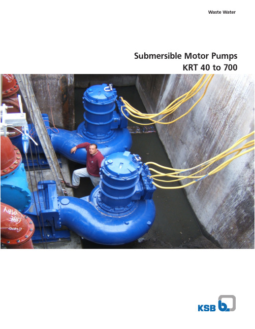
Waste Water Submersible Motor PumpsKRT 40 to 700Three (3) 161 hp Dry-Pit Pumps with cooling jacketKRT Submersible motor pumps for Versatile ApplicationsAdvantages and technical features:• economical installation• wet installation submersible motor pumps operate submerged in the pump sump• low building costs, eliminating intermediate shaft, drainage pump and superstructure• pump stations below ground do not spoil the landscape, traffic areas remain unchanged when sumps are located under roads • the compact pump/motor sets require less space and are easier to install• with the double pump guides the pump can be installed at any installation depth and withdrawn without difficulties • no need to enter the pump sump to carry out inspection and maintenance work• smaller inspection opening on duplex pump sets• small pump sump due to high permissible switching frequency • stationary and portable applications possible, see types of installations• permanent dry well installation possible where the pump is exposed to the danger of occasional flooding • minimum assembly and maintenance work• no coupling to be aligned since KRT pump and motor have a common shaft• no sealing or flushing water required or leakage outlet • motor cooled by the medium• high operation safety (dry running possible)• quiet operationKRT submersible motor pumps are highly efficient in the handling of:- raw sewage containing solid and long fibrous mixtures - contaminated liquids with a high gas and air content - liquids containing sludge and solid substances - concentrated sludge (KRT with agitator) for circulating and mixing the medium prior to pumping - floating sludge and debris such as vegetable wastes, wood chips and similar waste (KRT as a vacuum suction pump on a pontoon)- dirty water and storm water - raw and activated sludge - flume and wash water - pulp- slaughter house wastes - water/product suspensions - sand/cement/water mixtures - plastic granules in liquid - textile effluent- industrial effluent and wash water as well as media in production plants, e.g. flume water, scale wastes, cutting oil and other media containing abrasive components.- chemical and waste disposal effluent with pH-values 2 to 12- effluent containing acid- seawater and brackish water as well as other media with chlorine.Type of construction:KRT submersible motor pumps are submerged, single stage close-coupled pump sets. Depending on the liquid to be pumped and the size of the pump different impel -ler shapes are used: K - Closed non-clogging 2 or 3 vane impeller E - Single vane impeller F - Vortex impellerS - Cutting or Grinding impellerD - Open single vane impellerFields of application:Two (2) 148 hp Submersible Pumps with cooling jacket.1 - Reliable Motor - specifically designed for submersible pumps with air filled housings, explosion proof ratings, continuous duty cycles and automatic monitoring of winding temperature and moisture.2 - Water Tight Cable Entry - power cables with grommet and washer. Cable entry further epoxy sealed to insure no liquid gets inside the motor even if the cables are severed below water level.3 - Non-proprietary silicon carbide faced mechanical seals mounted in tandem in an oil bath.4 - Pump and motor shafts of stainless steel or Gr 1045 carbon steel protected and isolated by stainless steel shaft sleeves.5 - Flexible Hydraulic System - enclosed 1, 2 and 3 vane, recessed, grinder or open single vane impellers available to allow a hydraulic selection ideally suited for a particular application.6 - Major castings of ASTM A 48 Class 35 B cast iron, duplex stainless steel and wear resistant chromium white iron to Brinell 1000 available.7 - Automatic discharge connections with a positive seal between pump and elbow insures zero leakage.8 - Hard metal wear rings maintain hydraulic efficiency.The Safe and Reliable SolutionMotors smaller than ~80 hp :Motors 5 hp and below :9 - Major castings of ASTM A 48 Class 40 B cast iron, duplex stainless steel and wear resistant chromium white iron to Brinell 1000 available.10 - Plug in cable entry for a simple, polarized connection, fast pump installation and removal.11 - All-in-one bearing, seal, and gasket kits that areinterchangeable for all pump sizes, reducing spare parts costs.• 12 •• 3• 4• 5• 7• 910 •• 1• 4• 5• 6• 7• 3• 82 •The right impeller design for cost effective and reliable operationSince no one type of impeller is equally suitable for all applica -tions, KSB offers the KRT series of submersible motor pump with various types of impellers according to specific requirements. Our range of vortex, single vane and non-clogging impellers allows thebest impeller to be selected for the product with due consideration of operating parameters such as flow rate, head, efficiency, solidsize, wear behavior and gas content.Flexible installationsStationary guide wire installationStationary guide rail installationTransportable installationDryinstallationStationary guide wire or guide rail installation - for installation in the pump sump with suspension device ensuring automatic pres -sure-tight coupling of the pump.Transportable installation - with base stand and flange connection for pipework or hose connection (e.g. with rigid coupling)Dry installation - for installation in a separate dry well.The Pump That Keeps Cool1 - Cable Entry - absolutely water tight even in the event of damage to the cable sheath and core insulation there is no possibility of mositure entering the motor chamber along the strands due to capillary action.2 - Thermal Motor Protection - extensive sensor technology for permanent monitoring to ensure trouble-free operation.3 - High Efficiency Motor - all motors FM approved for Class I, Division 1 Group C & D hazardous locations.4 - OPTIONAL Closed-loop Cooling System - optimal cooling in all operating conditions with no external cooling required, perfect for dry-well installations .5 - Non- proprietary silicon carbide faced mechanical seals mounted in tandem in an oil bath.6 - Major Casting of ASTM A 48 Class 35 B Cast iron, Duplex Stainless steel and wear resistant Chromium White Iron.7 - Heat exchanger and separate coolant circulating impeller for optional cooling jacket.8 - Enclosed 1, 2 and 3 vane or recessed impellers available to allow a hydraulic selection ideally suited for a particular application.9 - Wear rings in hard metal to insure continued high efficiences and long impeller life.10 - Pump and motor shafts of stainless steel or Gr 1045 carbon steel protected and isolated by stainless steel shaft sleeves.11 - Temperature monitoring available for lower bearing12 - Float sensor in separate leakage collection chamber. Prevents leakage from reaching motor or lower bearing.* Motors larger than ~80 hp:• 1• 2• 3• 4• 6• 8• 910 •11 •12 •• 5• 7* For certain models, 30, 40, 50, 56, and 74 HP motors with cooling jacket are also available.06Installations and Technical DataThree (3) 12“ discharge, 161 hp closed-loop cooling dry-pit pumps with stainless steel Jacket in existing pumping station.Dry Well InstallationsTwo (2) large 24“ discharge, 148 hp Submersible Pumps with stainless steel cooling jacket on KSB guide rail system for an effluent waste water treatment pumping station.Wet Well Installations Three (3) 10“ discharge, 194 hp closed-loop cooling dry-pit pumps with stainless steel Jacket in existing pumping station.Two (2) large 24“ discharge, 251 hp Submersible Pumps and one (1) 12“ discharge, 80 hp on KSB guide cable system for a stormwater station.Technical DataOperating Data Pump Size - DN 2” - 30”Capacity - Q (gpm)up to 45,000Head - H (ft)up to 330Liquid Temperature - t (°F)up to 140Motor Rating - P (hp)up to 1,080Material Options Cast Iron A 48 Class 35 B Wear Resistant Chromium White IronA 532 II C 15% CrMo-HcDuplex Stainless Steel A 743 CD 4 MCU Part Designation GG1G2GHHC1C2Pump Casing A 48 Class 35 BA532 II C 15% CrMo-Hc A 743 CD 4 MCU Intermediate Casing A 48 Class 35 BA 532 II C 15% CrMo-HcA 743 CD 4 MCU Shaft A 276 Type 420;A 576 Gr. 1045 w/shaft protection sleeve A 276 S 31803/A 576 Gr. 1045ImpellerA 48 class 35B A 743 CD 4 MCU A 532 IIC 15% CrMo-HcA 276 S 31803/A 576 Gr. 1045Motor Casing A 48 Class 35 BA 743 CD 4 MCU Discharge Elbow A 48 Class 35 BA 532 II C 15% CrMo-HcA 743 CD 4 MCUPower/Control CableNeopreneKSB, Inc.4415 Sarellen Road Henrico, VA 2553.031/2-14 / 02.10 © K S B I n c 2008Your local KSB representative:S u b j e c t t o t e c h n i c a l m o d i f i c a t i o n w i t h o u t p r i o r n o t i c e。
斯伦贝谢-高级完井技术

完井工具-封隔器
机械坐封式封隔器
SOT-1 10K Omega SFB1
液压坐封式封隔器
Hydro - 5 Hydro-6
插管式封隔器
L ,QL,B
HSP
Omegamatic
Hydro-12
Omegatrieve
SR-1 ,SR-2
Compression
XHP, MRP, HQL
Quantum
封隔器的 ISO14310 资格认证
–安全阀与封隔器
•气井完井在中国的应用 •先进的完井技术
–流动控制阀 –Sensa光纤分布式温度系统
•多分支井技术 •我们的计划
斯伦贝谢完井技术在中国的气井中的应用
• 中石油塔里木油田牙哈30口高压气井完井项目; • 中石油塔里木西气东输克拉2高压气井完井项目
–克拉205井、克拉2 气田一期4口高压气井项目 ;
• 中石化西北分公司雅-大凝析油气田; • 中石化中原高新注气井项目; • 中石油-北京市政府大港储气库项目 ; • 中石油吐哈油田温米注气项目 ; • 中海油渤中26-2项目 ; • BP-ARCO三亚崖城131高压气田项目 ;
牙哈气田
• 10,000Psi(70MPa); • CO2 、H2S; • 永久式封隔器; • 13Cr; • 气密封扣; • 温度130 DegC。
–流动控制阀 –Sensa光纤分布式温度系统
•多分支井技术 •我们的计划
井眼产出物的检测和控制
检测和控制水和气的 进入 气
水
油藏监测和控制
油藏和井的响应
控制流出物或注入 优化
电力和数据传输
监控压力、 温度和产量
数据传输
更新模型和井动态
Fybroc Series 1500 高性能纤维glas 抗腐性泵说明书
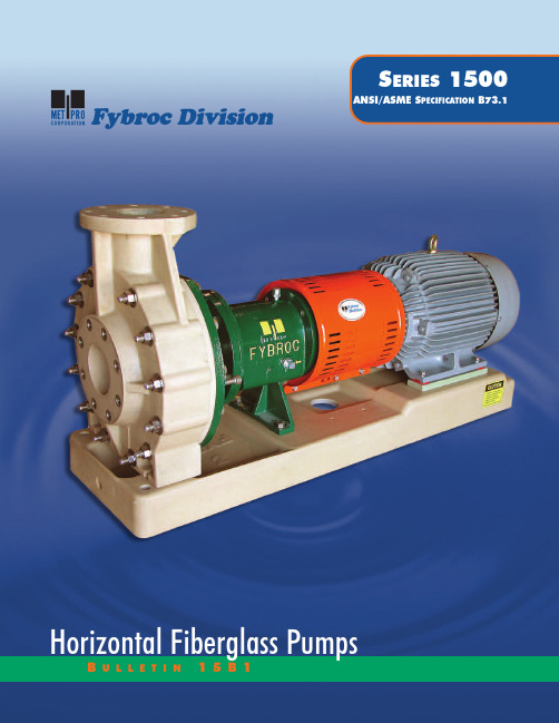
Fybroc DivisionS ERIES 1500ANSI/ASME S PECIFICATION B73.1BU L L E T I N15B 1Horizontal Fiberglass PumpsFYBROC – THE LEADER IN CORROSION-RESISTANT FIBERGLASS PUMPING EQUIPMENTFybroc is an advanced technology pump manufacturer specializing in reinforced composite centrifugal pumps, designed to handle corrosive liquids. Fybroc, the pioneer in the fiberglass pump field, con-tinues its position of leadership with its Series 1500 pump. This line is the culmination of many years of experience in producing high quality, corrosion-resistant pumps.The Series 1500 combines an extensive knowledge of materials and production techniques to provide exception-al structural integrity, excellent corrosion resistance, and dependable service in difficult operating environments.2MATERIALS OF CONSTRUCTION ARE AVAILABLEFOR A WIDE RANGE OF CORROSIVE LIQUIDSOnly Fybroc has the flexibility in materials selection tosolve your difficult corrosive or abrasive pump problems.•VR-1, vinyl ester resin: used for the vast majority ofcorrosive applications including most acids,caustics, brines, sea water, and wastewater.•VR-1 BPO-DMA, vinyl ester resin with BPO-DMAcure system: used to accommodate applications forspecific corrosion resistance to bleaches such assodium hypochlorite (NaOCl) and hydrogenperoxide (H2O2).•VR-1A, vinyl ester resin with abrasive resistantmaterial: used for pumping liquids with lowconcentration highly abrasive fines such asfly ash, diatomaceous earth or titaniumdioxide.•VR-1V,vinyl ester resin with synthet-i cveil: protection used specifically forfluoridic applications such ashydrofluoric acid (HF) and fluosilicicacid (H2SiF6).•EY-2, epoxy resin: offers outstand-ing chemical resistance for aggres-sive chemical/compounds, acids,and solvents. Ideal for high concen-trations of sulfuric acid (up to98%).FDA COMPLIANCEThe Dow DERAKANE series epoxy vinyl ester resinutilized by Fybroc, when properly formulated and cured,will comply with the U.S. Food, Drug, and Cosmetic Act,as amended, and applicable FDA regulations (21 CFR177.2420). These resins may be used as articles or com-ponents of articles intended forrepeated use in contact with food,subject to certain limitationsdescribed in that regulation.For further information on corro-sion resistance to specificchemicals, please refer tothe Fybroc website at.FYBROC SERIES 1500THERMOSET CONSTRUCTION RESIN TRANSFER MOLDING (RTM) PROCESS FOR SUPERIOR STRENGTH AND CORROSION RESISTANCEThermoset fiberglass reinforced plastic (FRP) pumps are increasingly being used in the pump industry due to their low weight, durability, and tailor-made properties. A ther-moset is a material that cures or hardens (sets) into a given shape, generally through the reaction with a cata-lyst. Curing is an irreversible chemical reaction in which permanent connections (cross-links) are made between a material’s molecular chains. The cross-links give the cured polymer a three-dimensional structure, as well as a higher degree of rigidity than it possessed prior to curing. It is important to note that a thermoset material will not re-melt or otherwise regain the processibility it had before being cured. Thermoset materials outperform other materials (thermoplastics, for example) in a number of areas, including the following: mechanical properties, chemical resistance, thermal stability, and overall durability.The fiberglass components in the Series 1500 Series pumps, as well as Fybroc’s complete line of centrifugal pumps, utilize the Resin Transfer Molding process. This process allows for the controlled placement of continu-ous-strand fiberglass mat in high stress areas.Specifically, sheets of contin-uous-strand fiberglassmat are die cut intospecific shapes andthen loaded intomatched-metal diemolds. After load-ing, the molds areclosed and theninjected with cat-alyzed resin into a sin-gle inlet port withnumerous vent ports toensure complete air displace-ment. After the resin gels, the part is removed and allowed to cure at ambient temperature, and then the part is post-cured in a controlled heat operation. The major advantage of the RTM process, unlike a compression molded process that inherently utilizes randomly oriented pieces of chopped fiberglass leadingto comparatively lower strength, is that the carefully ori-ented continuous-strand fiberglass mat provides com-ponents with excellent physical strength and properties.In addition, the process allows for the design of thinner-walled structures, thereby permitting the use of nearlypure resin systems for optimum corrosion resistance.The bottom line is that RTM is a manufacturing tech-nique that optimizes both strength and corrosion resist-ance.Critical components such as the single-piece casing, withits heavily gusseted suction and discharge flanges, bene-fit from the reinforcing properties of the RTM process. Thispermits the handling of normal pipe loads under full working pressures. Furthermore, this method of rein-forcement in the impeller extends the life of this compo-nent and provides unparalled strength without degrada-tion in corrosive environments.With more than thirty years of composite pump designand manufacturing experience, Fybroc has the expertiseto provide you with a composite pump line of the highestquality and durability for your specific service or applica-tion. Remember, FRP pumps are our ONLY business! By controlling the entire manufacturing process in-house,Fybroc is able to offer flexibility with special customer requirements while boasting the best lead times in the industry.3CORROSION-RESISTANT FIBERGLASS BASEPLATESFybroc manufactures fiberglass baseplates since chem-ical pumps are often used and installed in environ-ments where external corrosion can be a serious prob-lem. The baseplates are constructed of fiberglass-rein-forced vinyl ester resin utilizing continuous-strand rein-forcement for maximum strength and stiffness. In addi-tion, they accommodate ANS I/ASME dimensioned pumps (and NEMA/I EC motors) with an integral, sloped drip pan under the pump, a tapped drain con-nection, and a provision for a grouted foundation. Refer to page 13 for additional baseplate information and specifications.DESIGN FEATURES OF THE SERIES 1500 PUMPThe Fybroc Series 1500 pump is designed for broadcorrosion-resistance through the use of high quality1213 materials and state-of-the-art engineering. I ts simplicityand versatility make it the ideal choice for all demandingpumping requirements.The fiberglass components are manufactured utilizing theResin Transfer Molding technique which enables completecontrol of the fiberglass reinforcement in high stressareas. Metallic pump components are NOT in contactwith process fluids.1411109 41.ANSI/ASME B73.1 CONFOR-MANCE ensures maximum interchange-ability with existing metal ANSI pumps,thereby eliminating any need for piping or foundation changes when up-grading an installation to Fybroc Series 1500pumps.2.SMOOTH HYDRAULIC PASSAGES promote increased pump efficiency.3.SINGLE ONE-PIECE GUSSETED CASINGeasily withstands the rigors of normal plant piping loads.4.IMPELLER PUMP-OUT VANES and relief holes minimize axial unbalance and lower stuffing box pressure.5.ALLOY INSERT (integrally molded with impeller) with rounded edges carries impeller torque loads with low stress.6.VERSATILE CASING COVER is suit-able for use with most single outside or double inside mechanical seals without modifications. See page 7 for some of the most frequently used configurations and page 8 for seal flush considera-tions.7.CONTINUOUS-STRAND FIBER-GLASS CONSTRUCTION for all wet-ted parts in either vinyl ester or epoxy resin provides maximum corrosion resist-ance for a wide range of difficult liquids.8.CASING THROUGH-BOLTS maintain casing o-ring seal integrity under all hydraulic operating conditions.9.INTEGRAL SHAFT SLEEVE design eliminates gaskets and o-rings andprotects the pump shaft from exposure to the process fluid.10.LARGE-CAPACITY BEARINGS ensure operating life well in excess of the minimum specified by ANSI/ASME B73.1.11.EXTERNAL IMPELLER ADJUST-MENT allows field setting of impeller-to-casing clearance.12.HEAVY -DUTY SHAFT minimizesdeflec-tion to maximize mechanical seal life.13.POLYESTER THERMOSETTINGPOWDER COATED POWER FRAME components prevent external corrosion.14.LABYRINTH OIL SEALS nickel plated-bronze for longer life. Improved oil containment.876543215The Series 1500 pumps have been designed to maximize the life of bearings and mechanical seals which can deteriorate because of shaft deflection resulting from radial thrust. Radial thrust is the force acting on the side of an impeller as a result of the non-uniform distribution of pressure around the pump casing at off-peak opera-tion.The magnitude of this thrust varies with the flow, but the amount of radial thrust can roughly be cut in half by uti-lizing a double volute casing. The solid line in the chart to the right depicts the typical radial thrust characteristic of a single volute casing. The dotted line portrays the use of a double volute casing and the resulting reduction in radial thrust.The drawing at lower right shows the location of the “cutwater” in volute casings. The cutwater is the close clearance extension of the casing located at the base of the volute. Also, shown in orange, is the second cutwater or “splitter” used in the double volute casing, which channels half of the flow to the pump discharge. The split-ter reduces the pressure imbalance in the casing during off-peak flows and reduces both radial thrust and its resulting shaft deflection. Fybroc uses double volute cas-ings in eleven of its larger pump sizes where, typically,radial thrust loadings are higher. See chart on page 9,Casing Data, Volute.MATERIALS OF CONSTRUCTION10090807060504030201000102030405060708090100110120130140% OF DESIGN FLOW% O F M A X I M U M R A D I A L T H R U S TDouble VoluteSingle VoluteSplitterCutwaterConsult Factory for materials availability for your specific pump size.6DESIGN PROVIDES FOR MAXIMUM SEAL AND BEARING LIFECOMPONENTMATERIALSCasing VR-1, VR-1 BPO-DMA, VR-1A, VR-1V , EY-2Impeller VR-1, VR-1 BPO-DMA, VR-1A, VR-1V , EY-2Cover VR-1, VR-1 BPO-DMA, VR-1A, VR-1V , EY-2Gland VR-1, VR-1 BPO-DMA, EY-2Shaft 303SS (Optional 316SS)Bearing Hsg.Polyester Thermosetting Powder Coated Iron Adapter Polyester Thermosetting Powder Coated Iron Hardware 303SS (Optional hardware is available)O-RingsViton A (Optional elastomers are available)Fybroc Series 1500 pumps are available with a wide variety of mechanical seal arrangements. For corro-sive fluid handling, single outside and double inside seals are recommended. The single outside seals have non-metallic wetted parts and all metal components located outside the pump. The double inside mechan-ical seals have metallic parts that are exposed to buffer fluid only and are designed to limit the process fluid contact to non-metallic components.The following illustrations outline some commonly used sealing arrangements. See page 8 for seal flush con-siderations. Additional mechanical seal configurations (for example, cartridge designs) are available as options.C RANE 8B2F LOWSERVE RACC RANE T YPE 8-1T F LOWSERVE RXO7MECHANICAL SEALINTEGRAL IMPELLER AND•“ONE-PIECE” impeller and shaft sleeve •“NO” shaft sleeve o-rings required•Semi-open type with pump-out vanes and bal-ance holes designed to minimize axial unbalance and lower stuffing box pressureAll mechanical seals require flushing to lubricate the seal faces and maintain normal operating temperatures. Seals are normally flushed with either a clean external fluid or by the liquid being pumped. Fybroc Series 1500 pumps are furnished, as standard, with tapped glands for connection to the flush liquid or with theoptional configurations shown below.INTERNAL COVER FLUSHFybroc’s Internal Cover Flush option eliminates the need for external flushing of single mechanical seals from the pump discharge, which also eliminates the possible breakage of external tubing and fittings.This option removes seal heat by circulating high pressure liquid internally through the drilled cover to the seal chamber and then recirculating this liquid back to the low pressure side of the pump.FYBROC’S OPTIONAL FLUSH ASSEM BLY PACKAGEThe flush assembly* consists of the following items:1)Shut off valve and pressure gauge mounted on epoxy-coat-ed steel bracket. Inlet side.2)Solenoid valve and flow meter/metering valve mounted onepoxy-coated steel bracket. Outlet side.3)Necessary tubing and fittings to pipe system to seal gland.*Note:The assembly is intended for use on pumps with double inside mechanical seals (Crane 8-1T, Flowserve RXO). Consult Factory for additional “special” configurations.The system is designed to operate as follows:1)Flush water is brought to the inlet side of the system andpiped away to a suitable drain on the outlet side.2)The normally closed solenoid valve is wired into the motorstarter controls and opens when the motor is energized.3)The inlet shut-off valve would remain open at all times andwould be used only when the system needed to be isolatedfor maintenance purposes.4)The flow meter/metering valve would be adjusted as neces-sary to obtain a reading of 1/4 - 1/2GPM.When properly installed and operated as referenced above, the flush system will ensure that the mechanical seal is operating in the proper environment and is being cooled and lubricated as required.LowPressureLiquid High PressureLiquid8SEAL FLUSHING ARRANGEMENTSDIMENSIONS SHOWN ARE IN INCHES AND(MILLIMETERS )L 3/D 4* – T HE LOWER THE NUMBER , THE STIFFER THE SHAFT(ANDTHEREFORE LESS SHAFT DEFLECTION AND IMPROVED MECHANICAL SEAL LIFE ).9I MPELLER F RONT .015.020.025(.38)(.51)(.64)C LEARANCEB ACK.045.040.035(1.04)(1.02)(.89)C ASING T HICKNESS (M IN ).500.750.625.75.625 1.125.750 1.250 1.375(12.70)(19.05)(15.90)(19.05)(15.90)(28.60)(19.05)(31.75)(35.00)V OLUTES INGLED OUBLE S INGLED OUBLE S INGLED OUBLED IA . AT I MPELLER .750 1.250 1.500(19.05)(31.75)(38.10)D IA . U NDER S LEEVE 1.125 1.750 2.500(28.60)(44.45)(63.50)D IA . AT B EARINGS IB/OB 1.375/1.375 1.968/1.771 2.755/2.755(35.00/35.00)(50.00/45.00)(70.00/70.00)D IA . B ETWEEN B EARINGS1.6252.2503.250(41.30)(57.15)(82.55)B EARING S PAN 3.7907.09010.250(96.30)(180.10)(260.35)D IA . AT C OUPLING.875 1.125 2.375(22.22)(28.60)(60.32)B EARING N O . I NBOARD 307MZC3310MZC36314ZC3B EARING N O . O UTBOARD 5207AZC35309EZC35314ZC3M AX . S HAFT HP (KW) PER 100 RPM1.14(.85 KW)4.00(2.98 KW)14.80(11.04 KW)L-10 L IFE M INIMUM 3 Y EARS (26,280 H OURS )L 3/D 4*1524632B EARING F RAME G ROUP I II IIIO IL C APACITY , P INTS (l ).375(.18 l ) 2.000(.95 l )5.000(2.37 l )S LEEVE (O.D.) 1.375 2.125 2.875(35.00)(54.00)(73.00)S TUFFING B OX B ORE2.000 2.8753.750(50.80)(73.02)(95.25)M AX . D EPTHOFB OX2.7503.250 3.500(69.85)(82.55)(88.90)P ACKING S IZE 5/16 x 5/163/8 x 3/87/16 x 7/16(7.94 x 7.94)(9.52 X 9.52)(11.11 X 11.11)D ISTANCE T O 3.140 3.980 4.870F IRST O BSTRUCTION(79.76)(101.10)(123.70)ENGINEERING INFORMATION –1 x 1.5 x 61.5 x 3 x 62 x3 x 61 x 1.5 x 81.5 x 3 x 82 x3 x 83 x4 x 81 x2 x 101.5 x 3 x 102 x3 x 103 x4 x 104 x 4 x 104 x 6 x 102 x3 x 133 x4 x 134 x 6 x 136 x 8 x 138 x 10 x 1510 x 12 x 16PUMP IMPELLER DIAMETERX SUCTION X DISCHARGEANSI DESIGNATION AA AB –AA A50A60A70A05A50A60A70–A80A30A40A80A90A120–MAX. SPHERE SIZE .375.500.313.625 1.000.188.375.625.750 1.000.313.500 1.0001.1251.7501.375(9.53)(12.70)(7.95)(15.90)(25.40)(4.78)(9.53)(15.90)(19.05)(25.40)(7.95)(12.70)(25.40)(28.60)(44.45)(35.00)C A S I N GD A T AB O X D A T AS H A F T A N D B E A R I N G D A T A1150 RPM60 HERTZ1750 RPM60 HERTZ3500 RPM60 HERTZNOTE:For specific performancecurves refer to curve book or .1X11/2X611/2X3X62X3X63X4X82X3X811/2X3X81X11/2X81X2X102X3X1311/2X3X102X3X103X4X104X4X104X6X103X4X134X6X136X8X138X10X1510X12X16123510152030406080100150200CUBIC METERS PER HOUR1020305010015020030050010002000400060003005007001000150015010080605040302010535302520151052T O T A L H E A D I N M E T E R S123510152030406080100150200CUBIC METERS PER HOUR10203050100150200300500100020004000600030050070010001500250200150100806050403020107060504030252015105T O T A L H E A D I N M E T E R S1X11/2X611/2X3X62X3X63X4X82X3X811/2X3X81X11/2X81X2X102X3X1311/2X3X102X3X103X4X104X4X104X6X103X4X134X6X136X8X138X10X15123510152030406080CUBIC METERS PER HOUR51020304050100150200300500100020001001502003006005004003002001501008060504030201501201008060504030252015108T O T A L H E A D I N M E T E R S1X11/2X611/2X3X62X3X63X4X811/2X3X81X11/2X81X2X1011/2X3X102X3X103X4X104X4X102X3X8T O T A L H E A D I N F E E TT O T A L H E A D I N F E E TT O T A L H E A D I N F E E TUS GALLONS PER MINUTEUS GALLONS PER MINUTEUS GALLONS PER MINUTE10FYBROC SERIES 1500 – THE INDUSTRY’S MOST EXTENSIVE FIBERGLASS CORROSION-RESISTANT COVERAGESHAFT HORSEPOWER (KW)PRESSURE–TE M PERATURE RAT-1450 RPM50 HERTZ2900 RPM50 HERTZ751020304050TEMPERATURE - °C607080901001101205025-10-180100125150175200225250K I L O P A S C A L – k PaTEMPERATURE - °FGROUP II *GROUP III (Except 10x12x16)10x12x16M A X I M U M W O R K I N G P R E S S U R E – P S I 025507510012515017520022525015030045060075090010501200135015001650GROUP I* Standard flat faced flanges (ANSI/ASME B16.5 Class 150)NOTE: Refer to Chemical Compatibility Guide for specific application ratings.11RPM 35002900175014501150Group I 40 HP 33 HP 20 HP 17 HP 13 HP (30 KW)(25 KW)(15 KW)(12 KW)(9.8 KW)Group II 140 HP 116 HP 70 HP 58 HP 46 HP (104 KW)(88KW)(52 KW)(43 KW)(34 KW)Group III *——260 HP 215 HP 170 HP (194 KW)(160 KW)(127 KW)* 1150 RPM maximum for 10x12x16PUMP DIMENSIONS FOR SERIES 1500CPFYV XDE 1E2øHUDIMENSIONS SHOWN ARE IN INCHES AND (MILLIMETERS)*CF—Consult Factory (FRP baseplate available up to 365T frame)121 x 1.5 x 61.5 x 3 x 62 x3 x 61 x 1.5 x 81.5 x 3 x 82 x3 x 83 x4 x 81 x2 x 101.5 x 3 x 102 x3 x 103 x4 x 104 x 4 x 104 x 6 x 102 x3 x 133 x4 x 134 x 6 x 136 x 8 x 138 x 10 x 1510 x 12 x 16PUMP IMPELLERX SUCTION X DISCHARGEANSI DESIGNATION AA AB –AA A50A60A70A05A50A60A70–A80A30A40A80A90A120–ISO/DIN F LANGE A VAILABILITY ––✔––✔✔✔–✔✔✔✔–✔✔✔✔✔JIS F LANGE A VAILABILITY––✔––✔✔✔–✔✔✔✔–✔✔✔✔✔CP 171/2231/2337/8351/8(445)(597)(860)(892)D 51/481/410141/218(133)(210)(254)(368)(457)X 61/281/291/21181/291/211121/2131/2111/2121/2131/2161926(165)(216)(242)(280)(216)(242)(280)(318)(343)(292)(318)(343)(406)(483)(660)F 71/4121/2183/4173/4(184)(318)(476)(541**)2E 1693/41622(152)(248)(406)(559)2E 2071/4914(0)(184)(229)(356)H 5/87/81(16)(22)(25)U 7/811/823/8(22.23)(28.58)(60.33)KEYWAY 3/16x 3/321/4x 1/85/8x 5/16(4.76 x 2.38)(6.35 x 3.18)(15.88 x 7.94)V 225/84(51)(67)(102)Y 467(102)(152)(178)M OTOR F RAME 143T-184T143T-145T254T-365TB ASEPLATE M ODEL #1T 25M OTOR F RAME 213T-215T182T-286T404TS-445T*CFB ASEPLATE M ODEL #2T 26M OTOR F RAME 254T-256T324T-405TS—B ASEPLATE M ODEL #13—Mount your pump on a corrosion-resistant fiberglass baseplate from Fybroc.•Corrosion resistanceFybroc fiberglass baseplates are designed specifically for use in corrosive environments, providing the same corro-sion-resistance as our time-proven Fybroc fiberglass pumps.•High strengthA high percentage of continuous-strand fiberglass mat reinforces the corrosion-resistant resin, thereby giving the baseplate an exceptional degree of strength.•Integral drip pan with rim constructionEach Fybroc fiberglass baseplate incorporates an integral,sloped drip pan, eliminating expensive alloy drip pans and/or rimmed baseplates.• EconomyFybroc fiberglass baseplates resist corrosion indefinitely,thus eliminating the operational and maintenance costs of replacing corroded baseplates.•ANSI/ASME dimensionsEvery Fybroc fiberglass baseplate is pre-drilled to accept all ANSI/AMSE pumps and NEMA/IEC frame motors.•Optional Baseplate DesignsConsult Factory for modified FRP baseplates as well as other materials such as polymer concrete (composite)and steel baseplate designs.HEHEHAC3/4 NPTDrainHGHBHF HLHM11/4 (32)øHHDIMENSIONS SHOWN ARE IN INCHES AND (MILLIMETERS)*Note: Dimension varies with pump model†Model 4 base13BASEPLATE DIMENSIONSBASE PLATE HA HB HE HF HG HH HL HM CMODEL 1T 10(254)35(890)4(102)321/2(825)25/8(67)3/4(19)41/2(114)33/8(86)111/16(43)2T 12(305)39(990)41/2(114)361/2(927)27/8(73)3/4(19)41/2(114)27/8(73)115/16(49)112(305)45(1140)41/2(114)421/2(1080)33/4(95)3/4(19)41/2(114)23/4(70)17/8(47)215(381)52(1320)6(152)491/2(1257)33/4(95)3/4(19)41/2(114)33/4(95)17/8(47)318(457)58(1475)71/2(191)551/2(1410)4(102)1(25)41/2(114)4(102)17/8(47)†418(457)60(1525)71/2(191)571/2(1460)4(102)1(25)*NOTE 4(102)N/A 522(559)68(1727)91/2(241)651/2(1664)41/2(114)1(25)61/2(165)41/2(114)11/2(38)622(559)80(2032)91/2(241)771/2(1969)41/2(114)1(25)61/2(165)41/2(114)11/2(38)14OPTIONS DESIGNED TO ELIMINATE ALIGNMENT PROBLEMSCLOSE-COUPLED PUMPS•Capacities to 1500 GPM (345 m 3/hr)•Heads to 400 Ft (125 m)•C-faced JM extension motors up to 50 HP (37 KW)•Sixteen sizes (all Fybroc Series 1500 Group I and Group II pumps)•Available with all materials of construction (page 2)•Available for mounting on FRP baseplates •Lightweight/space efficient design•Anti-spin-off device (segment key/locking ring) incorpo-rated on the back end of the impeller sleeve to help protect against potential reverse rotation damage.•Available on all Fybroc Series 1500 Group I and Group II pumpsGroup I – motor frame sizes up to 256TC Group II – motor frame sizes up to 365TSC •Designed to simplify pump/motor installation and alignment•Reduces routine maintenanceC-FACEINTERCHANGEABILITYEXTENSIVE INTERCHANGEABILITY SIMPLIFIES SPARE PARTS STOCKING REQUIREMENTS.G ROUP I P UMPSG ROUP II P UMPSG ROUP II P UMPS15©COPYRIGHT 2004 MET Fybroc Division IS A REGISTERED TRADEMARK OF MET -PRO CORPORATION TOLL-FREE: 1-800-FYBROC-1, Phone: (215) 723-8155, FAX: (215) 723-2197EY-2 EPOXY RESIN (FRP)PUMPS•Identical construction (thermoset) and molding process (RTM) as pumps manufactured utilizing vinyl ester resin (VR-1)•Available in all pump configurations: centrifugal (ANSI /ASME dimensioned), close-coupled, self-priming,mag-drive, vertical sump, cantilever•Excellent corrosion resistance with aggressive, solvent-based chemicals•Ideal for concentrated sulfuric acid (98%)•Higher maximum temperature capabilities, in certain applications, compared to vinyl ester resin (VR-1)•Typical markets include pharmaceutical, petrochemical,fertilizer, and pesticide. Also, EY-2 allows expanded opportunities for Fybroc pumps in existing markets such as electronics, chemical process, and metal finishing.。
斯伦贝谢POWER-V
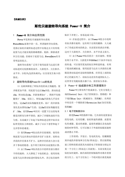
【机械仪表】斯伦贝谢旋转导向系统 Power-V 简介1 Power-V 简介和应用范围Power-V是斯伦贝谢旋转导向系统PowerDrive家族中的一员。
所谓旋转导向系统,是指让钻柱在旋转钻进过程中实现过去只有传统泥浆马达才能实现的准确增斜、稳斜、降斜或者纠方位功能,但相对于泥浆马达,PowerDrive有非常明显的优点。
旋转导向系统广泛用于使用泥浆马达进行滑动钻进时比较困难的深井、大斜度井、大位移井、水平井、分枝井(包括鱼刺井),以及易发生粘卡的情况。
2 旋转导向系统PowerDrive的优点⑴反映和降低了所钻井段的真正狗腿度,使井眼更加平滑。
用泥浆马达打30m井段,滑动钻进15m,转动钻进15m,井斜角增加4°,得到平均狗腿度4°/30m。
实际上,转钻15m井斜角几乎没有变化,这15m的实际狗腿度是零;而4°的井斜角变化是由滑钻15m产生的,这15m的实际狗腿度是8°/30m。
而用Power-V在同一设置下打出的每米都是同样均匀和平滑的,减少了井眼轨迹的不均匀度,从而减少了在起下钻和钻进过程中钻具实际所受的拉力和扭矩,减少了以后下套管和起下完井管串的难度。
⑵使用Power-V钻出的井径很规则。
使用传统泥浆马达在滑动井段的井径扩大很多,而转动井段的井径基本不扩大。
这种井径的忽大忽小是井下事故的隐患,也不利于固井时水泥量的计算。
⑶由于Power-V钻具组合中的所有部分都在不停的旋转,大大降低了卡钻的机会。
使用传统泥浆马达在滑动钻进时除钻头外,其它钻具始终贴在下井壁上,容易造成卡钻。
⑷在钻进过程中,由于Power-V组合中的所有钻具都在旋转,这有利于岩屑的搬移,大大减少了形成岩屑床的机会,从而更好的清洁井眼。
这对于大斜度井、大位移井、水平井意义很大。
⑸由于Power-V钻具组合一直在旋转,特别有利于水平井、大斜度井和3000m以下深井中钻压的传递,可以使用更高的钻压和转盘转速,有利于提高机械钻速。
斯伦贝谢的马达手册.

Anadrill PowerPak Steerable Motor Handbook1.0 介绍1.1 钻井马达的发展1.2 PowerPak马达的设计和测试1.3 应用2.0 PowerPak马达描述2.1 顶部接头2.2 动力部分2.3 传动部分2.4 轴承部分和驱动轴2.5 弯壳部分和连接扣型3.0 作业3.1 常用参数3.2 狗腿严重度限制3.3 工作准备3.4 马达的现场操作3.5 空气钻井3.6 短半径钻井3.7 打捞马达4.0 地质导向系统5.0 操作参数6.0 司钻手册1。
2 PowerPak 的设计和测试PowerPak马达是根据DD的要求而设计的,特别需要强调的是,粗糙,朴素,已证明的技术已经转变为了在工作现场占优势的,可信赖的作业。
Anadrill 遵循使井底系统接近最小的噪音对MWD测量数据的干扰,以及确保PowerPak马达不会限制排量和其它的钻井作业的原则。
为期18个月的系统分析和部件测试计划开始于1990年。
这项综合计划包括全尺寸的的功率计和钻机操作测试,利用位于Texas Sugar Land 的Anadrill的先进的测试设备。
已设计一项工程维修计划,包括时间表和部件跟踪。
从早在1992年的采用开始,PowerPak马达已经连续地达到或接近设计目标,为了它的可靠性,操作和维修成本,而且,对于改进效率和降低钻井成本,已经建立了一个新的标准。
PowerPak马达特性●PowerPak导向马达设计有标准组件,以使它们能够在对MWD干扰最小的情况下适应更广泛的定向井作业。
可以通过马达部件的选择,优化其在任何一种钻井条件下的作业。
●PowerPak马达的泥浆润滑轴承特性适合恶劣的钻井环境。
●多种多样的定转子形状允许PowerPak马达可用于低速高扭和高速低扭这两种情况。
●地面可调节弯壳体(SAB)改进了效率,增加了在现场的钻井控制能力。
●锻钢驱动轴提高了马达的强度。
●密封的传动组合阻止泥浆损害,从而提高了马达寿命。
斯伦贝谢PVTi参考手册---工作流程
说明1、这段翻译文字是斯伦贝谢参考手册《教程》一章中第五节工作流程()。
2、标记为红色字体的,是认为翻译欠妥的文字,请查看原文。
本人水平有限,文中肯定有很多不不妥和错误之处,希望广大果友批评指正,跟帖讨论的学习心得及经验,大家共同进步。
工作流程()该教程将逐步介绍的功能。
注意:该教程不准备讲解分析,但是会关注并举例说明的典型工作流程。
每个教程分为数量不等的若干部分,为避免重复,后面的教程会用到前面的教程,所以强烈推荐你按照顺序来阅读。
包括以下教程:一、流体属性预测()34页二、创建流体系统 37页三、模拟实验 43页四、实验结果与状态方程的拟合 50页五、输出 54页六、将黑油模型转化成组份模型 58页七、工作流程教程 61页八、多相闪蒸 69页九、输出 73页十、资料(或数据)分析与质量控制 77页十一、排除样品污染 84页十二、调用旧工程用于当前工程 87页一、流体属性预测()该节教程阐明的是如何使用模块进行流体属性预测()。
该教程中的数据可按照标准安装路径如下:$2007.1在使用该节教程之前,你必须先将该文件拷贝到你自己的本地文件夹中。
该教程分为以下几个部分:1.介绍 34页2.基本信息 34页3.闪蒸计算 36页4.结论 36页1、介绍流体属性预测能够提供一种快速查看井场所提供的属性表的功能。
饱和压力(泡点或者露点压力)连同油藏组成已经足够输入并提供快速查看功能,给予一个初始的流体性质预测以方便实验室中的全流体分析。
完成该节教程的学习之后,你应该能够使用这个数值模拟工具来进行流体属性预测。
2、基础信息1、启动(如果你不知道如何启动,请查看31页“启动”)。
2、输入作为新工程的文件名。
提示:当在中建立一个新的、空的工程时,窗口会自动打开。
如果想在其它任何时候打开窗口,可选择:。
窗口允许你输入最少的信息是至少能创建一个完整的状态方程模型。
3、点击“”复选框。
提示:你在实验室报告中看到的摩尔百分数来源于组份的质量百分数和摩尔质量。
- 1、下载文档前请自行甄别文档内容的完整性,平台不提供额外的编辑、内容补充、找答案等附加服务。
- 2、"仅部分预览"的文档,不可在线预览部分如存在完整性等问题,可反馈申请退款(可完整预览的文档不适用该条件!)。
- 3、如文档侵犯您的权益,请联系客服反馈,我们会尽快为您处理(人工客服工作时间:9:00-18:30)。
18 Initials
*: Mark of Schlumberger
2.9 存储卡数据下载
- 点击”Read Module” -点击”Load Trend”
Schlumberger Private Schlumberger Private
19 Initials
*: Mark of Schlumberger
Schlumberger Private Schlumberger Private
*: Mark of Schlumberger
2.5 Uniconn操作-查看泵工况数据
Schlumberger Private Schlumberger Private
12 Intouch #4057132 1/2/2012
格式化/设置 存储卡
15 Initials
状态显示
*: Mark of Schlumberger
2.7.2 Uniconn操作 – 存储卡设置/格式化
格式化存储卡
Schlumberger Private Schlumberger Private
16 Initials
一旦选择yes,系统将删除存储卡以前的内容
Schlumberger Private Schlumberger Private
Adobe Acrobat Document
20 Intouch #4057132 1/2/2012
*: Mark of Schlumberger
3. 基本故障诊断
1. 2. 3. 4. PIC Fault – 需要进行PIC卡检测,井下绝缘监测
*: Mark of Schlumberger
2.7.3 Uniconn操作 – 存储卡设置/格式化
选择需要的参数添加到存 储卡,在以后的正常工作 中存储卡将按照所添加的 参数进行数据存储
Schlumberger Private Schlumberger Private
一旦选取“wrap data”在一段时间后新数据将复盖老数据
*: Mark of Schlumberger
2.7 Uniconn操作 – 存储卡设置/格式化
存储卡 1. 2. 3.
读卡器 (USB)
电脑
Star View
Schlumberger Private Schlumberger Private
将存储卡插入读卡器, 读卡器连接到电脑 打开桌面stariew软件 选择File目录下Uniconn Memberger Private Schlumberger Private
动力电缆
电机
泵工况 5 Intouch #4057132 1/2/2012
*: Mark of Schlumberger
1.4 井下设备
泵工况 0.56M, 法兰 4.5” 底部扣型:2-3/8 EUE BOX
keypad
Schlumberger Private Schlumberger Private
模拟/数值输入输出
DataCard Slot
9 Intouch #4057132 1/2/2012
4个扩展卡插槽
*: Mark of Schlumberger
2.3 Uniconn 扩展卡
Schlumberger Private Schlumberger Private
Schlumberger Private Schlumberger Private
斯伦贝谢电泵工况监测系统 泵工况监测系统
要点
1. 系统的组成和安装
Schlumberger Private Schlumberger Private
2. 操作事宜 3. 故障诊断
2 Intouch #4057132 1/2/2012
*: Mark of Schlumberger
1.2测量参数
参数
在地面设备上的英文显示
范围
准确度
吸入口压力 排出口压力 吸入口温度 电机绕组温度 震动 电流漏失
Pi Pd Ti Tm Vib Cl-a & Cl-p
0~400Bar (5800psi) 0~400Bar (5800psi) 0~125 ℃ 0~175 ℃ 0~15g 0~25mA
供电110vdc
Schlumberger Private Schlumberger Private
变频器输出
井口接线盒
变压器输出
7 Intouch #4057132 1/2/2012
*: Mark of Schlumberger
2.1 Uniconn 正视图
2 lines x 40 LED 显示屏 状态指示灯
14 Intouch #4057132 1/2/2012
*: Mark of Schlumberger
2.7.1 Uniconn操作 – 存储卡设置/格式化
数据库记录
显示数据卡内容
Schlumberger Private Schlumberger Private
加载所选数据库 转换数据库到文件 读取存储卡内容 读取存储卡文件 将数据内容转 换成曲线图 进度条 完成 / 退出 停止
通讯卡
泵工况功能卡
PIC 卡
10 Intouch #4057132 1/2/2012
*: Mark of Schlumberger
2.4 组件
扼流板
PIC卡
通讯卡 SCADA (RS232/485) 存储卡 读卡器 (USB) DB-9 数据线 StarView
11 Intouch #4057132 1/2/2012
Schlumberger Private Schlumberger Private
语言选择键
返回键 停止键
功能键 DB9 数据线接口
8 Intouch #4057132 1/2/2012
存储卡插槽及其退出按键
*: Mark of Schlumberger
2.2 Uniconn – 侧视图及后视图
保险
Schlumberger Private Schlumberger Private
百事可乐
22 Intouch #4057132 1/2/2012
*: Mark of Schlumberger
Schlumberger Private Schlumberger Private
Tool Open – 检查扼流板保险丝,以及相关的电缆连接 Tool ok – 正常状态 Tool short – 检查井下绝缘和相间值阻
21 Intouch #4057132 1/2/2012
*: Mark of Schlumberger
Schlumberger Private Schlumberger Private
压力传输管线 100FT OD 1/4” Jam nut 连接
传压接头 0.24M 3.5” EUE
OD 5’’
6 Intouch #4057132 1/2/2012
*: Mark of Schlumberger
1.6 地面设备
2.11 泵工况操作注意事项
1. 2. 3.
4.
由于泵工况的地面设备与控制柜内的高压电缆相连接,因此在对地面 设备进行工作之前一定要停泵并且断开控制柜的电源。 为了安全,泵工况在运行的时候不要打开地面设备箱。 在对井下电缆进行绝缘测试之前一定要将接到控制柜内的三条红色高 压线与井下电缆的连接断开。否则会导致地面设备的损坏。在测绝缘 时,测试电压不应该大于2500Vdc,推荐用1000Vdc来进行测量。将- VE接到电缆,+VE接地。如果测到井下电缆绝缘为0,一定要倒换表 笔再测一次,这样才能确定井下绝缘是否存在问题。 不要打火花放电。这样可能会导致井下泵工况内二极管的损坏。
*: Mark of Schlumberger
1.1 系统的组成
传压接头
压力管线
Schlumberger Private Schlumberger Private
动力电缆 ISU
供电110V 110V 供电110V
高压扼流板 Uniconn
信号反馈 4-20mA
泵工况 扶正器
3 Intouch #4057132 1/2/2012
*: Mark of Schlumberger
2.6 Uniconn操作 - RSR 快速取样模式
RSR 快速采样模式:只针对吸入口压力参数进行一秒钟采集一次,同时其他参数处于暂停状态
Schlumberger Private Schlumberger Private
13 Intouch #4057132 1/2/2012
17 Initials
*: Mark of Schlumberger
2.8 存储卡下载数据
- 将存储卡从Uniconn上弹开 ;
注意: 点击 “退出” 按钮,等待数秒当屏幕显示 “Ready to unplug”
Schlumberger Private Schlumberger Private
- 将存储卡插入到读卡器并连接到电脑的USB接口 - 运行star view 软件 - 选择File 目录下的“Uniconn Mem Module”
0.7bar (10psi) 0.7bar (10psi) 1% 1% 1% 0.05%
Schlumberger Private Schlumberger Private
4 Intouch #4057132 1/2/2012
*: Mark of Schlumberger
1.3 原理
显示面板
变频器
ISP/Uniconn 输出110vdc 经过扼流板(高低压隔离), 加载到井下电泵的动力电缆, 直达电机底部的星点,提供泵 工况工作电压。 泵工况得电,正常工作,并且 将产生的模拟信号通过接地反 馈到地面ISU/Uniconn