ASTM D638-01 塑料拉伸强度测定
拉伸强度测试标准
拉伸强度测试标准拉伸强度是材料在拉伸过程中抵抗破坏的能力,是材料力学性能的重要指标之一、拉伸强度测试是通过在材料上施加拉应力并测量其抗拉力和断裂长度来进行的。
拉伸强度测试标准是为了确保测试过程的一致性和可比性而制定的具体规范和指导文件。
本文将介绍一些常见的拉伸强度测试标准。
1.ASTMD638ASTMD638是美国材料与试验协会(ASTM)制定的一项用于测量塑料拉伸强度的标准。
该标准规定了测试方法、试样形状和尺寸、试验设备和数据分析方法等内容,以确保测试结果的准确性和可重复性。
2.ISO527ISO527是国际标准化组织(ISO)制定的一项用于测量塑料拉伸性能的标准。
它与ASTMD638类似,提供了详细的测试程序和要求,以便不同实验室之间的测试结果可进行比较。
3.GB/T1040GB/T1040是中国国家标准化管理委员会制定的一项用于测量塑料拉伸性能的标准。
该标准包括了试样制备、测试方法、数据计算和报告格式等方面的规定,以确保测试结果的可重复性和可比性。
4.JISK7161JISK7161是日本工业标准化国际化组织(JIS)制定的一项用于测量塑料拉伸强度的标准。
它提供了详细的试验条件和要求,以确保测试结果的准确性和可靠性。
这些标准不仅适用于塑料材料的拉伸强度测试,还可用于金属、橡胶、纤维等材料的拉伸强度测试。
在进行拉伸强度测试时,需要按照标准规定的试样尺寸和测试方法进行操作,并记录测试过程中的相关数据,如应力-应变曲线、最大应力、断裂长度等。
同时,还应注意测试环境的控制,包括温度、湿度和试样制备等方面的要求。
拉伸强度测试标准的制定和遵守对于材料的研发、质量控制和产品设计都具有重要意义。
准确的拉伸强度测试结果可以为材料的性能评价、产品设计和工业应用提供参考依据,从而保证产品的可靠性和安全性。
因此,在进行拉伸强度测试时,应严格按照相应的标准操作,确保测试结果的准确性和可靠性。
ASTM D638 塑料 拉伸
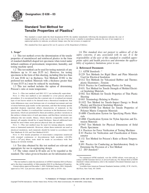
Designation:D638–03Standard Test Method forTensile Properties of Plastics1This standard is issued under thefixed designation D638;the number immediately following the designation indicates the year of original adoption or,in the case of revision,the year of last revision.A number in parentheses indicates the year of last reapproval.A superscript epsilon(e)indicates an editorial change since the last revision or reapproval.This standard has been approved for use by agencies of the Department of Defense.1.Scope*1.1This test method covers the determination of the tensile properties of unreinforced and reinforced plastics in the form of standard dumbbell-shaped test specimens when tested under defined conditions of pretreatment,temperature,humidity,and testing machine speed.1.2This test method can be used for testing materials of any thickness up to14mm[0.55in.].However,for testing specimens in the form of thin sheeting,includingfilm less than 1.0mm[0.04in.]in thickness,Test Methods D882is the preferred test method.Materials with a thickness greater than 14mm[0.55in.]must be reduced by machining.1.3This test method includes the option of determining Poisson’s ratio at room temperature.N OTE1—This test method and ISO527-1are technically equivalent. N OTE2—This test method is not intended to cover precise physical procedures.It is recognized that the constant rate of crosshead movement type of test leaves much to be desired from a theoretical standpoint,that wide differences may exist between rate of crosshead movement and rate of strain between gage marks on the specimen,and that the testing speeds specified disguise important effects characteristic of materials in the plastic state.Further,it is realized that variations in the thicknesses of test specimens,which are permitted by these procedures,produce variations in the surface-volume ratios of such specimens,and that these variations may influence the test results.Hence,where directly comparable results are desired,all samples should be of equal thickness.Special additional tests should be used where more precise physical data are needed.N OTE3—This test method may be used for testing phenolic molded resin or laminated materials.However,where these materials are used as electrical insulation,such materials should be tested in accordance with Test Methods D229and Test Method D651.N OTE4—For tensile properties of resin-matrix composites reinforced with oriented continuous or discontinuous high modulus>20-GPa [>3.03106-psi]fibers,tests shall be made in accordance with Test Method D3039/D3039M.1.4Test data obtained by this test method are relevant and appropriate for use in engineering design.1.5The values stated in SI units are to be regarded as the standard.The values given in brackets are for information only.1.6This standard does not purport to address all of the safety concerns,if any,associated with its use.It is the responsibility of the user of this standard to establish appro-priate safety and health practices and determine the applica-bility of regulatory limitations prior to use.2.Referenced Documents2.1ASTM Standards:2D229Test Methods for Rigid Sheet and Plate Materials Used for Electrical InsulationD412Test Methods for Vulcanized Rubber and Thermo-plastic Elastomers—TensionD618Practice for Conditioning Plastics for TestingD651Test Method for Tensile Strength of Molded Electri-cal Insulating MaterialsD882Test Methods for Tensile Properties of Thin Plastic SheetingD883Terminology Relating to PlasticsD1822Test Method for Tensile-Impact Energy to Break Plastics and Electrical Insulating MaterialsD3039/D3039M Test Method for Tensile Properties of Polymer Matrix Composite MaterialsD4000Classification System for Specifying Plastic Mate-rialsD4066Classification System for Nylon Injection and Ex-trusion MaterialsD5947Test Methods for Physical Dimensions of Solid Plastic SpecimensE4Practices for Force Verification of Testing Machines E83Practice for Verification and Classification of Exten-someterE132Test Method for Poisson’s Ratio at Room Tempera-tureE691Practice for Conducting an Interlaboratory Study to Determine the Precision of a Test Method2.2ISO Standard:31This test method is under the jurisdiction of ASTM Committee D20on Plastics and is the direct responsibility of Subcommittee D20.10on Mechanical Properties.Current edition approved December1,2003.Published January2004.Originally approved st previous edition approved in2002as D638-02a.2For referenced ASTM standards,visit the ASTM website,,or contact ASTM Customer Service at service@.For Annual Book of ASTM Standards volume information,refer to the standard’s Document Summary page on the ASTM website.3Available from American National Standards Institute(ANSI),25W.43rd St., 4th Floor,New York,NY10036.1*A Summary of Changes section appears at the end of this standard. Copyright©ASTM International,100Barr Harbor Drive,PO Box C700,West Conshohocken,PA19428-2959,United States.ISO527-1Determination of Tensile Properties3.Terminology3.1Definitions—Definitions of terms applying to this test method appear in Terminology D883and Annex A2.4.Significance and Use4.1This test method is designed to produce tensile property data for the control and specification of plastic materials.These data are also useful for qualitative characterization and for research and development.For many materials,there may be a specification that requires the use of this test method,but with some procedural modifications that take precedence when adhering to the specification.Therefore,it is advisable to refer to that material specification before using this test method. Table1in Classification D4000lists the ASTM materials standards that currently exist.4.2Tensile properties may vary with specimen preparation and with speed and environment of testing.Consequently, where precise comparative results are desired,these factors must be carefully controlled.4.2.1It is realized that a material cannot be tested without also testing the method of preparation of that material.Hence, when comparative tests of materials per se are desired,the greatest care must be exercised to ensure that all samples are prepared in exactly the same way,unless the test is to include the effects of sample preparation.Similarly,for referee pur-poses or comparisons within any given series of specimens, care must be taken to secure the maximum degree of unifor-mity in details of preparation,treatment,and handling.4.3Tensile properties may provide useful data for plastics engineering design purposes.However,because of the high degree of sensitivity exhibited by many plastics to rate of straining and environmental conditions,data obtained by this test method cannot be considered valid for applications involv-ing load-time scales or environments widely different from those of this test method.In cases of such dissimilarity,no reliable estimation of the limit of usefulness can be made for most plastics.This sensitivity to rate of straining and environ-ment necessitates testing over a broad load-time scale(includ-ing impact and creep)and range of environmental conditions if tensile properties are to suffice for engineering design pur-poses.N OTE5—Since the existence of a true elastic limit in plastics(as in many other organic materials and in many metals)is debatable,the propriety of applying the term“elastic modulus”in its quoted,generally accepted definition to describe the“stiffness”or“rigidity”of a plastic has been seriously questioned.The exact stress-strain characteristics of plastic materials are highly dependent on such factors as rate of application of stress,temperature,previous history of specimen,etc.However,stress-strain curves for plastics,determined as described in this test method, almost always show a linear region at low stresses,and a straight line drawn tangent to this portion of the curve permits calculation of an elastic modulus of the usually defined type.Such a constant is useful if its arbitrary nature and dependence on time,temperature,and similar factors are realized.4.4Poisson’s Ratio—When uniaxial tensile force is applied to a solid,the solid stretches in the direction of the applied force(axially),but it also contracts in both dimensions lateral to the applied force.If the solid is homogeneous and isotropic,and the material remains elastic under the action of the applied force,the lateral strain bears a constant relationship to the axial strain.This constant,called Poisson’s ratio,is defined as the negative ratio of the transverse(negative)to axial strain under uniaxial stress.4.4.1Poisson’s ratio is used for the design of structures in which all dimensional changes resulting from the application of force need to be taken into account and in the application of the generalized theory of elasticity to structural analysis.N OTE6—The accuracy of the determination of Poisson’s ratio is usually limited by the accuracy of the transverse strain measurements because the percentage errors in these measurements are usually greater than in the axial strain measurements.Since a ratio rather than an absolute quantity is measured,it is only necessary to know accurately the relative value of the calibration factors of the extensometers.Also,in general,the value of the applied loads need not be known accurately.5.Apparatus5.1Testing Machine—A testing machine of the constant-rate-of-crosshead-movement type and comprising essentially the following:5.1.1Fixed Member—Afixed or essentially stationary member carrying one grip.5.1.2Movable Member—A movable member carrying a second grip.5.1.3Grips—Grips for holding the test specimen between thefixed member and the movable member of the testing machine can be either thefixed or self-aligning type.5.1.3.1Fixed grips are rigidly attached to thefixed and movable members of the testing machine.When this type of grip is used extreme care should be taken to ensure that the test specimen is inserted and clamped so that the long axis of the test specimen coincides with the direction of pull through the center line of the grip assembly.5.1.3.2Self-aligning grips are attached to thefixed and movable members of the testing machine in such a manner that they will move freely into alignment as soon as any load is applied so that the long axis of the test specimen will coincide with the direction of the applied pull through the center line of the grip assembly.The specimens should be aligned as per-fectly as possible with the direction of pull so that no rotary motion that may induce slippage will occur in the grips;there is a limit to the amount of misalignment self-aligning grips will accommodate.5.1.3.3The test specimen shall be held in such a way that slippage relative to the grips is prevented insofar as possible. Grip surfaces that are deeply scored or serrated with a pattern similar to those of a coarse single-cutfile,serrations about2.4 mm[0.09in.]apart and about1.6mm[0.06in.]deep,have been found satisfactory for most thermoplastics.Finer serra-tions have been found to be more satisfactory for harder plastics,such as the thermosetting materials.The serrations should be kept clean and sharp.Breaking in the grips may occur at times,even when deep serrations or abraded specimen surfaces are used;other techniques must be used in these cases. Other techniques that have been found useful,particularly with smooth-faced grips,are abrading that portion of the surface of the specimen that will be in the grips,and interposingthinpieces of abrasive cloth,abrasive paper,or plastic,or rubber-coated fabric,commonly called hospital sheeting,between the specimen and the grip surface.No.80double-sided abrasive paper has been found effective in many cases.An open-mesh fabric,in which the threads are coated with abrasive,has also been effective.Reducing the cross-sectional area of the speci-men may also be effective.The use of special types of grips is sometimes necessary to eliminate slippage and breakage in the grips.5.1.4Drive Mechanism—A drive mechanism for imparting to the movable member a uniform,controlled velocity with respect to the stationary member,with this velocity to be regulated as specified in Section8.5.1.5Load Indicator—A suitable load-indicating mecha-nism capable of showing the total tensile load carried by the test specimen when held by the grips.This mechanism shall be essentially free of inertia lag at the specified rate of testing and shall indicate the load with an accuracy of61%of the indicated value,or better.The accuracy of the testing machine shall be verified in accordance with Practices E4.N OTE7—Experience has shown that many testing machines now in use are incapable of maintaining accuracy for as long as the periods between inspection recommended in Practices E4.Hence,it is recommended that each machine be studied individually and verified as often as may be found necessary.It frequently will be necessary to perform this function daily.5.1.6Thefixed member,movable member,drive mecha-nism,and grips shall be constructed of such materials and in such proportions that the total elastic longitudinal strain of the system constituted by these parts does not exceed1%of the total longitudinal strain between the two gage marks on the test specimen at any time during the test and at any load up to the rated capacity of the machine.5.1.7Crosshead Extension Indicator—A suitable extension indicating mechanism capable of showing the amount of change in the separation of the grips,that is,crosshead movement.This mechanism shall be essentially free of inertial lag at the specified rate of testing and shall indicate the crosshead movement with an accuracy of610%of the indicated value.5.2Extension Indicator(extensometer)—A suitable instru-ment shall be used for determining the distance between two designated points within the gage length of the test specimen as the specimen is stretched.For referee purposes,the extensom-eter must be set at the full gage length of the specimen,as shown in Fig.1.It is desirable,but not essential,that this instrument automatically record this distance,or any change in it,as a function of the load on the test specimen or of the elapsed time from the start of the test,or both.If only the latter is obtained,load-time data must also be taken.This instrument shall be essentially free of inertia at the specified speed of testing.Extensometers shall be classified and their calibration periodically verified in accordance with Practice E83.5.2.1Modulus-of-Elasticity Measurements—For modulus-of-elasticity measurements,an extensometer with a maximum strain error of0.0002mm/mm[in./in.]that automatically and continuously records shall be used.An extensometer classified by Practice E83as fulfilling the requirements of a B-2classification within the range of use for modulus measure-ments meets this requirement.5.2.2Low-Extension Measurements—For elongation-at-yield and low-extension measurements(nominally20%or less),the same above extensometer,attenuated to20%exten-sion,may be used.In any case,the extensometer system must meet at least Class C(Practice E83)requirements,which include afixed strain error of0.001strain or61.0%of the indicated strain,whichever is greater.5.2.3High-Extension Measurements—For making mea-surements at elongations greater than20%,measuring tech-niques with error no greater than610%of the measured value are acceptable.5.2.4Poisson’s Ratio—Bi-axial extensometer or axial and transverse extensometers capable of recording axial strain and transverse strain simultaneously.The extensometers shall be capable of measuring the change in strains with an accuracy of 1%of the relevant value or better.N OTE8—Strain gages can be used as an alternative method to measure axial and transverse strain;however,proper techniques for mounting strain gages are crucial to obtaining accurate data.Consult strain gage suppliers for instruction and training in these special techniques.5.3Micrometers—Apparatus for measuring the width and thickness of the test specimen shall comply with the require-ments of Test Method D5947.6.Test Specimens6.1Sheet,Plate,and Molded Plastics:6.1.1Rigid and Semirigid Plastics—The test specimen shall conform to the dimensions shown in Fig. 1.The Type I specimen is the preferred specimen and shall be used where sufficient material having a thickness of7mm[0.28in.]or less is available.The Type II specimen may be used when a material does not break in the narrow section with the preferred Type I specimen.The Type V specimen shall be used where only limited material having a thickness of4mm[0.16in.]or less is available for evaluation,or where a large number of specimens are to be exposed in a limited space(thermal and environmental stability tests,etc.).The Type IV specimen should be used when direct comparisons are required between materials in different rigidity cases(that is,nonrigid and semirigid).The Type III specimen must be used for all materials with a thickness of greater than7mm[0.28in.]but not more than14mm[0.55in.].6.1.2Nonrigid Plastics—The test specimen shall conform to the dimensions shown in Fig.1.The Type IV specimen shall be used for testing nonrigid plastics with a thickness of4mm [0.16in.]or less.The Type III specimen must be used for all materials with a thickness greater than7mm[0.28in.]but not more than14mm[0.55in.].6.1.3Reinforced Composites—The test specimen for rein-forced composites,including highly orthotropic laminates, shall conform to the dimensions of the Type I specimen shown in Fig.1.6.1.4Preparation—Test specimens shall be prepared by machining operations,or die cutting,from materials in sheet, plate,slab,or similar form.Materials thicker than14mm[0.55Specimen Dimensions for Thickness,T ,mm [in.]ADimensions (see drawings)7[0.28]or under Over 7to 14[0.28to 0.55],incl4[0.16]or under Tolerances Type I Type II Type III Type IV B Type V C ,D W —Width of narrow section E ,F 13[0.50]6[0.25]19[0.75]6[0.25] 3.18[0.125]60.5[60.02]B ,C L —Length of narrow section 57[2.25]57[2.25]57[2.25]33[1.30]9.53[0.375]60.5[60.02]C WO —Width overall,min G 19[0.75]19[0.75]29[1.13]19[0.75]...+6.4[+0.25]WO —Width overall,min G ............9.53[0.375]+3.18[+0.125]LO —Length overall,min H 165[6.5]183[7.2]246[9.7]115[4.5]63.5[2.5]no max [no max]G —Gage length I 50[2.00]50[2.00]50[2.00]...7.62[0.300]60.25[60.010]C G —Gage length I.........25[1.00]...60.13[60.005]D —Distance between grips 115[4.5]135[5.3]115[4.5]65[2.5]J 25.4[1.0]65[60.2]R —Radius of fillet76[3.00]76[3.00]76[3.00]14[0.56]12.7[0.5]61[60.04]C RO —Outer radius (Type IV).........25[1.00]...61[60.04]AThickness,T ,shall be 3.260.4mm [0.1360.02in.]for all types of molded specimens,and for other Types I and II specimens where possible.If specimens are machined from sheets or plates,thickness,T ,may be the thickness of the sheet or plate provided this does not exceed the range stated for the intended specimen type.For sheets of nominal thickness greater than 14mm [0.55in.]the specimens shall be machined to 1460.4mm [0.5560.02in.]in thickness,for use with the Type III specimen.For sheets of nominal thickness between 14and 51mm [0.55and 2in.]approximately equal amounts shall be machined from each surface.For thicker sheets both surfaces of the specimen shall be machined,and the location of the specimen with reference to the original thickness of the sheet shall be noted.Tolerances on thickness less than 14mm [0.55in.]shall be those standard for the grade of material tested.BFor the Type IV specimen,the internal width of the narrow section of the die shall be 6.0060.05mm [0.25060.002in.].The dimensions are essentially those of Die C in Test Methods D 412.CThe Type V specimen shall be machined or die cut to the dimensions shown,or molded in a mold whose cavity has these dimensions.The dimensions shall be:W =3.1860.03mm [0.12560.001in.],L =9.5360.08mm [0.37560.003in.],G =7.6260.02mm [0.30060.001in.],and R =12.760.08mm [0.50060.003in.].The other tolerances are those in the table.DSupporting data on the introduction of the L specimen of Test Method D 1822as the Type V specimen are available from ASTM Headquarters.Request RR:D20-1038.EThe width at the center W c shall be +0.00mm,−0.10mm [+0.000in.,−0.004in.]compared with width W at other parts of the reduced section.Any reduction in W at the center shall be gradual,equally on each side so that no abrupt changes in dimension result.FFor molded specimens,a draft of not over 0.13mm [0.005in.]may be allowed for either Type I or II specimens 3.2mm [0.13in.]in thickness,and this should be taken into account when calculating width of the specimen.Thus a typical section of a molded Type I specimen,having the maximum allowable draft,could be as follows:GOverall widths greater than the minimum indicated may be desirable for some materials in order to avoid breaking in the grips.HOverall lengths greater than the minimum indicated may be desirable either to avoid breaking in the grips or to satisfy special test requirements.ITest marks or initial extensometer span.JWhen self-tightening grips are used,for highly extensible polymers,the distance between grips will depend upon the types of grips used and may not be critical if maintained uniform once chosen.FIG.1Tension Test Specimens for Sheet,Plate,and Molded Plasticsin.]must be machined to 14mm [0.55in.]for use as Type III specimens.Specimens can also be prepared by molding the material to be tested.N OTE 9—Test results have shown that for some materials such as glasscloth,SMC,and BMC laminates,other specimen types should be considered to ensure breakage within the gage length of the specimen,as mandated by 7.3.N OTE 10—When preparing specimens from certain composite lami-nates such as woven roving,or glass cloth,care must be exercised in cutting the specimens parallel to the reinforcement.The reinforcement will be significantly weakened by cutting on a bias,resulting in lower laminate properties,unless testing of specimens in a direction other than parallel with the reinforcement constitutes a variable being studied.N OTE 11—Specimens prepared by injection molding may have different tensile properties than specimens prepared by machining or die-cutting because of the orientation induced.This effect may be more pronounced in specimens with narrow sections.6.2Rigid Tubes —The test specimen for rigid tubes shall be as shown in Fig.2.The length,L ,shall be as shown in the table in Fig.2.A groove shall be machined around the outside of the specimen at the center of its length so that the wall section after machining shall be 60%of the original nominal wall thick-ness.This groove shall consist of a straight section 57.2mm [2.25in.]in length with a radius of 76mm [3in.]at each end joining it to the outside diameter.Steel or brass plugs having diameters such that they will fit snugly inside the tube and having a length equal to the full jaw length plus 25mm [1in.]shall be placed in the ends of the specimens to prevent crushing.They can be located conveniently in the tube by separating and supporting them on a threaded metal rod.Details of plugs and test assembly are shown in Fig.2.6.3Rigid Rods —The test specimen for rigid rods shall be as shown in Fig.3.The length,L ,shall be as shown in the table in Fig.3.A groove shall be machined around the specimen at the center of its length so that the diameter of the machined portion shall be 60%of the original nominal diameter.This groove shall consist of a straight section 57.2mm [2.25in.]in length with a radius of 76mm [3in.]at each end joining it to the outside diameter.6.4All surfaces of the specimen shall be free of visible flaws,scratches,or imperfections.Marks left by coarse ma-chining operations shall be carefully removed with a fine file or abrasive,and the filed surfaces shall then be smoothed with abrasive paper (No.00or finer).The finishing sanding strokes shall be made in a direction parallel to the long axis of the test specimen.All flash shall be removed from a molded specimen,taking great care not to disturb the molded surfaces.In machining a specimen,undercuts that would exceed the dimensional tolerances shown in Fig.1shall be scrupulously avoided.Care shall also be taken to avoid other common machining errors.6.5If it is necessary to place gage marks on the specimen,this shall be done with a wax crayon or India ink that will not affect the material being tested.Gage marks shall not be scratched,punched,or impressed on the specimen.6.6When testing materials that are suspected of anisotropy,duplicate sets of test specimens shall be prepared,having their long axes respectively parallel with,and normal to,the suspected direction of anisotropy.7.Number of Test Specimens7.1Test at least five specimens for each sample in the case of isotropicmaterials.DIMENSIONS OF TUBE SPECIMENSNominal Wall ThicknessLength of Radial Sections,2R.S.Total CalculatedMinimum Length of SpecimenStandard Length,L ,of Specimen to Be Used for 89-mm [3.5-in.]Jaws Amm [in.]0.79[1⁄32]13.9[0.547]350[13.80]381[15]1.2[3⁄64]17.0[0.670]354[13.92]381[15]1.6[1⁄16]19.6[0.773]356[14.02]381[15]2.4[3⁄32]24.0[0.946]361[14.20]381[15]3.2[1⁄8]27.7[1.091]364[14.34]381[15]4.8[3⁄16]33.9[1.333]370[14.58]381[15]6.4[1⁄4]39.0[1.536]376[14.79]400[15.75]7.9[5⁄16]43.5[1.714]380[14.96]400[15.75]9.5[3⁄8]47.6[1.873]384[15.12]400[15.75]11.1[7⁄16]51.3[2.019]388[15.27]400[15.75]12.7[1⁄2]54.7[2.154]391[15.40]419[16.5]AFor other jaws greater than 89mm [3.5in.],the standard length shall be increased by twice the length of the jaws minus 178mm [7in.].The standard length permits a slippage of approximately 6.4to 12.7mm [0.25to 0.50in.]in each jaw while maintaining the maximum length of the jaw grip.FIG.2Diagram Showing Location of Tube Tension TestSpecimens in TestingMachine7.2Test ten specimens,five normal to,and five parallel with,the principle axis of anisotropy,for each sample in the case of anisotropic materials.7.3Discard specimens that break at some flaw,or that break outside of the narrow cross-sectional test section (Fig.1,dimension “L”),and make retests,unless such flaws constitute a variable to be studied.N OTE 12—Before testing,all transparent specimens should be inspected in a polariscope.Those which show atypical or concentrated strain patterns should be rejected,unless the effects of these residual strains constitute a variable to be studied.8.Speed of Testing8.1Speed of testing shall be the relative rate of motion of the grips or test fixtures during the test.The rate of motion of the driven grip or fixture when the testing machine is running idle may be used,if it can be shown that the resulting speed of testing is within the limits of variation allowed.8.2Choose the speed of testing from Table 1.Determine this chosen speed of testing by the specification for the material being tested,or by agreement between those concerned.When the speed is not specified,use the lowest speed shown in Table 1for the specimen geometry being used,which gives rupture within 1⁄2to 5-min testing time.8.3Modulus determinations may be made at the speed selected for the other tensile properties when the recorder response and resolution are adequate.8.4The speed of testing for Poisson’s ratio determination shall be 5mm/min.9.Conditioning9.1Conditioning —Condition the test specimens at 2362°C [73.463.6°F]and 5065%relative humidity for not less than 40h prior to test in accordance with Procedure A of Practice D 618,unless otherwise specified by contract or the relevant ASTM material specification.Reference pre-test con-ditioning,to settle disagreements,shall apply tolerances of 61°C [1.8°F]and 62%relative humidity.9.2Test Conditions —Conduct the tests at 2362°C [73.463.6°F]and 5065%relative humidity,unless otherwise specified by contract or the relevant ASTM material specifica-tion.Reference testing conditions,to settle disagreements,shall apply tolerances of 61°C [1.8°F]and 62%relativehumidity.DIMENSIONS OF ROD SPECIMENSNominal Diam-eter Length of RadialSections,2R.S.Total CalculatedMinimumLength of SpecimenStandard Length,L ,ofSpecimen to Be Usedfor 89-mm [31⁄2-in.]Jaws A mm [in.]3.2[1⁄8]19.6[0.773]356[14.02]381[15]4.7[1⁄16]24.0[0.946]361[14.20]381[15]6.4[1⁄4]27.7[1.091]364[14.34]381[15]9.5[3⁄8]33.9[1.333]370[14.58]381[15]12.7[1⁄2]39.0[1.536]376[14.79]400[15.75]15.9[5⁄8]43.5[1.714]380[14.96]400[15.75]19.0[3⁄4]47.6[1.873]384[15.12]400[15.75]22.2[7⁄8]51.5[2.019]388[15.27]400[15.75]25.4[1]54.7[2.154]391[15.40]419[16.5]31.8[11⁄4]60.9[2.398]398[15.65]419[16.5]38.1[11⁄2]66.4[2.615]403[15.87]419[16.5]42.5[13⁄4]71.4[2.812]408[16.06]419[16.5]50.8[2]76.0[2.993]412[16.24]432[17]AFor other jaws greater than 89mm [3.5in.],the standard length shall be increased by twice the length of the jaws minus 178mm [7in.].The standard length permits a slippage of approximately 6.4to 12.7mm [0.25to 0.50in.]in each jaw while maintaining the maximum length of the jaw grip.FIG.3Diagram Showing Location of Rod Tension Test Specimenin Testing MachineTABLE 1Designations for Speed of Testing AClassification B Specimen TypeSpeed of Testing,mm/min [in./min]Nominal Strain C Rate atStart of Test,mm/mm·min [in./in.·min]Rigid and SemirigidI,II,III rods and tubes5[0.2]625%0.150[2]610%1500[20]610%10IV5[0.2]625%0.1550[2]610% 1.5500[20]610%15V1[0.05]625%0.110[0.5]625%1100[5]625%10Nonrigid III 50[2]610%1500[20]610%10IV50[2]610% 1.5500[20]610%15ASelect the lowest speed that produces rupture in 1⁄2to 5min for the specimen geometry being used (see 8.2).BSee Terminology D 883for definitions.CThe initial rate of straining cannot be calculated exactly for dumbbell-shaped specimens because of extension,both in the reduced section outside the gage length and in the fillets.This initial strain rate can be measured from the initial slope of the tensile strain-versus-timediagram.。
ASTM D638 拉伸
ASTM/D638—91塑料拉伸性能的标准试验方法1.范围1.1当在预处理、温度、湿度和试验机速度预先定义的条件下进行试验,这个试验包含标准的哑铃形试样的没有增强型和增强型的塑料的拉伸性能的测定。
1.2这个试验方法可被使用于任何厚度到0。
55inch (14mm)的试验材料,然而对于薄片形式的试验样品,包括小于0.04inch(1。
0)厚度的薄膜,试验方法D882是所指的试验方法,对于厚度大于0.55inch的材料,一定通过机器加工使之减少。
注释1-对于试验方法D638的完全的测量参考已经发展到D638M注释2-这个试验方法并不包含精密的物理过程,横梁移动保持一个恒定的速率是我们理论上所期望的,在试样上传感器标记间的横梁移动速率和变形速率有很大的不同。
指定的试验速率在塑料状态下,对材料的性能有很大的影响,通过这些过程的试样厚度的变化是允许的,这些变化对结果几乎没有影响,所有的试样应该同一厚度,当需要更精密的物理数据时,额外的特殊的试验应该被使用.注释3-这个试验方法可被用于试验酚醛树酯或层压材料,这些材料可被用做电气绝缘,这样的材料应同试验方法D229和D651所述的那样来进行试验.注释4-对于树酯复合材料的增强,它带着定向的持续或不持续的高数>20KG纤维。
试验应按试验方法D3039来进行。
1.3磅为单位开始的值应被看作标准,在括号内给出的值仅供参考。
1.4这个标准设有注明所有的安全问题,如果和其使用有关,它是这个标准使用者的责任,他应建立恰当的安全和健康的实验操作并且在使用之前测定有规律限制的实用性。
2.参考的数据2.1ASTM标准对于电气绝缘使用的硬片材料的D229试验方法,固体电气绝缘的厚度的D374试验方法,拉伸的橡胶性能的D412试样方法,对于条件材料和电气绝缘材料的试验D618实验方法,对于塑料拉伸性能的D639试验方法,模塑电气绝缘材料的拉伸强度的D651试验方法。
薄膜拉伸性能的D882试验方法相关塑料的D883专门术语折断的塑料和电气绝缘材料的拉伸冲击能量的D1822试验方法.纤维树酯合成物的拉伸性能的D3030试验方法,指定的塑料的D4000分类系统。
ASTM D638 拉伸应变

ASTM D638 拉伸应变ASTM D638 是美国材料和试验协会(ASTM)制定的标准,用于测量塑料材料的拉伸应变性能。
该标准确定了用于测试不同类型塑料的标准试验方法。
试验目的ASTM D638 试验旨在评估塑料材料在拉伸加载下的性能,特别是其在应变发生时的表现。
该试验用于测量塑料材料的应变硬化、应力-应变曲线和断裂特性。
试验过程ASTM D638 标准描述了拉伸试验的具体步骤和要求。
主要步骤如下:1. 准备标准试样:根据标准规定的尺寸和形状,制备标准试样。
2. 安装试样:将试样安装在拉伸试验机上,确保其固定和对中。
3. 施加负荷:通过拉伸试验机施加逐渐增加的拉伸负荷,以引发试样断裂。
4. 记录数据:记录试样在不同负荷下的应变和应力数据。
5. 分析结果:根据数据绘制应力-应变曲线,并计算与塑料材料相关的性能指标。
结果解释通过 ASTM D638 拉伸试验可以得到以下结果和参数:1. 弹性模量(E):衡量塑料材料在拉伸应力下的变形程度。
2. 极限拉伸应力(UTS):试验中材料能够承受的最大拉伸应力。
3. 屈服应力(yield strength):材料开始产生塑性变形的应力。
4. 断裂强度(tensile strength):试验中材料断裂前的应力。
5. 弹性应变(strain):材料在拉伸过程中的变形程度。
这些结果可以帮助工程师和研究人员评估塑料材料的力学性能,并进行材料选择、设计和改善等方面的决策。
结论ASTM D638 拉伸试验是评估塑料材料拉伸应变性能的常用方法。
通过该试验可以得到塑料材料在拉伸加载下的性能指标,帮助研究人员和工程师进行材料选择和设计。
拉伸性能测试

拉伸性能测试(静态)拉伸性能测试主要确定材料的拉伸强度,为研究、开发、工程设计以及质量控制和标准规范提供数据。
在拉伸测试中,薄的薄膜会遇到一定困难。
拉伸试样的切边必须没有划痕或裂缝,避免薄膜从这些地方开始过早破裂。
对于更薄的薄膜,夹头表面是个问题。
必须避免夹头发滑、夹头处试样破裂。
任何防止夹头处试样发滑和破裂,而且不干扰试样测试部分的技术如在表面上使用薄的橡胶涂层或使用纱布等都可以接受。
从拉伸性能测试中可以得到拉伸模量、断裂伸长率、屈服应力和应变、拉伸强度和拉伸断裂能等材料性能。
ASTM D 638 (通用)[4]和ASTM D 882 [5](薄膜)中给出了塑料的拉伸性能(静态)。
拉伸强度拉伸强度是用最大载荷除以试样的初始截面面积得到的,表示为单位面积上的力(通常用MPa为单位)。
屈服强度屈服强度是屈服点处的载荷除以试样的初始截面面积得到的.用单位面积上的力(单位MPa)表示,通常有三位有效数字。
拉伸弹性模量拉伸弹性模量(简称为弹性模量,E)是刚性指数,而拉伸断裂能(TEB,或韧性)是断裂点处试样单位体积所吸收的总能量。
拉伸弹性模量计算如下:在载荷-拉伸曲线上初始线性部分画一条切线,在切线上任选一点,用拉伸力除以相应的应变即得(单位为MPa),实验报告通常有三位有效数字。
正割模量(应力-应变间没有初始线性比值时)定义为指定应变处的值。
将应力-应变曲线下单位体积能积分得到TEB,或者将吸收的总能量除以试样原有厚度处的体积积分。
TEB表示为单位体积的能量(单位为MJ/m3),实验报告通常有两位有效数字。
拉伸断裂强度拉伸断裂强度的计算与拉伸强度一样,但要用断裂载荷,而不是最大载荷。
应该注意的是,在大多数情况中,拉伸强度和拉伸断裂强度值相等。
断裂伸长率断裂伸长率是断裂点的拉伸除以初始长度值。
实验报告通常有两位有效数字。
屈服伸长率屈服伸长率是屈服点处的拉伸除以试样的初始长度值,实验报告通常有两位有效数字。
抗拉强度伸长率及断后伸长率测定方法
抗拉强度伸长率及断后伸长率测定方法抗拉强度(Tensile strength)是指材料在拉伸过程中,单位截面积上所能承受的最大拉力。
伸长率(Elongation)是指材料在拉伸过程中,单位长度延伸的比例。
断后伸长率(Reduction of area)是指材料在断裂后,截面缩小的比例。
抗拉强度、伸长率和断后伸长率是评估材料力学性能的重要指标,广泛应用于材料研究和工程设计中。
下面介绍几种常用的测定方法:1.标准拉伸试验法(ASTMD638):这是一种最常用的测定方法,适用于塑料、橡胶和金属材料等。
方法是在标准拉伸试验机上进行试验,将样品固定在两个夹具之间,施加恒定的拉力,逐渐增加,直至样品断裂。
根据拉伸试验曲线,可以确定材料的抗拉强度和伸长率。
2.带缩径试验法(ISO6892-1):这是一种适用于金属材料的测定方法。
方法是在标准缩径试验机上进行试验,将样品固定在两个夹具之间,施加恒定的拉力,逐渐增加。
当样品断裂后,测量断口的截面缩小的比例,即可得到断后伸长率。
3.加弹性测定法(ISO527-3):这是一种适用于塑料材料的测定方法。
方法是在标准拉伸试验机上进行试验,将样品固定在两个夹具之间,施加恒定的拉力,逐渐增加。
当样品发生明显的拉伸变形后,停止加载,测量样品恢复到初始长度所需的时间,即可得到伸长率。
4.分离试验法(ISO6892-1):这是一种适用于金属材料的测定方法。
方法是在标准拉伸试验机上进行试验,将样品固定在两个夹具之间,施加恒定的拉力。
在拉伸过程中,观察样品表面的裂纹扩展情况,直至样品断裂。
根据断裂前后样品的截面积,可以计算出抗拉强度和断后伸长率。
总结起来,抗拉强度、伸长率和断后伸长率的测定方法因材料不同而有所差异。
在进行测定时,需要根据具体材料的特性选择合适的方法,确保测量结果准确可靠。
这些测定方法对于材料制备和工程设计具有重要的指导意义,能够帮助提高材料的力学性能和工程质量。
拉伸性能测试

拉伸性能测试(静态)拉伸性能测试主要确定材料的拉伸强度,为研究、开发、工程设计以及质量控制和标准规范提供数据。
在拉伸测试中,薄的薄膜会遇到一定困难。
拉伸试样的切边必须没有划痕或裂缝,避免薄膜从这些地方开始过早破裂。
对于更薄的薄膜,夹头表面是个问题。
必须避免夹头发滑、夹头处试样破裂。
任何防止夹头处试样发滑和破裂,而且不干扰试样测试部分的技术如在表面上使用薄的橡胶涂层或使用纱布等都可以接受。
从拉伸性能测试中可以得到拉伸模量、断裂伸长率、屈服应力和应变、拉伸强度和拉伸断裂能等材料性能。
ASTM D 638 (通用)[4]和ASTM D 882 [5](薄膜)中给出了塑料的拉伸性能(静态)。
拉伸强度拉伸强度是用最大载荷除以试样的初始截面面积得到的,表示为单位面积上的力(通常用MPa为单位)。
屈服强度屈服强度是屈服点处的载荷除以试样的初始截面面积得到的.用单位面积上的力(单位MPa)表示,通常有三位有效数字。
拉伸弹性模量拉伸弹性模量(简称为弹性模量,E)是刚性指数,而拉伸断裂能(TEB,或韧性)是断裂点处试样单位体积所吸收的总能量。
拉伸弹性模量计算如下:在载荷-拉伸曲线上初始线性部分画一条切线,在切线上任选一点,用拉伸力除以相应的应变即得(单位为MPa),实验报告通常有三位有效数字。
正割模量(应力-应变间没有初始线性比值时)定义为指定应变处的值。
将应力-应变曲线下单位体积能积分得到TEB,或者将吸收的总能量除以试样原有厚度处的体积积分。
TEB表示为单位体积的能量(单位为MJ/m3),实验报告通常有两位有效数字。
拉伸断裂强度拉伸断裂强度的计算与拉伸强度一样,但要用断裂载荷,而不是最大载荷。
应该注意的是,在大多数情况中,拉伸强度和拉伸断裂强度值相等。
断裂伸长率断裂伸长率是断裂点的拉伸除以初始长度值。
实验报告通常有两位有效数字。
屈服伸长率屈服伸长率是屈服点处的拉伸除以试样的初始长度值,实验报告通常有两位有效数字。
ASTMD638塑料拉伸性能的测试方法

ASTM D638塑料拉伸性能的测试方法1.范畴1.1这测试方法包括加强和非加强塑料在规定的条件下如预处理,温度,湿度和测试速度以哑铃形状来测试它的拉伸性能。
1.2这测试方法被用在测试样品厚度不大于14MM的条件下.如测试样品是薄片和小于1MM的薄膜则首选测试方法D882.超过14MM的厚材料要通过机加工来减少厚度后再测试.1.3这测试方法包括了室温下泊松比测定的选择.注解1.这测试方法和ISO527-1技术上相当.注解2-这测试方法不是想包括精确的物理程序.它被认为测试十字头移动类型的恒定速度从理论观点上留下许多可得到,即十字头移动速度和样品上测试标记的应变速度之间会存在很大的差异,而且测试速度很大地掩饰了塑料在塑化状态下的特性结果.此外,它被认为测试样品被允许的厚度差异会产生样品的表面-体积比的差异,而且影响测试结果.因此,要想比较想要的结果,所有的样品要有同样的厚度.特别增加的测试需要更精确的物理数据.注解3-这测试方法可运于模压酚醛树脂和碾压材料.但是,如这些材料被用在电绝缘上则必需依据测试方法D229和D651.注解4-有矩阵树脂复合加强的连续定向和非连续高模量(>20GPA)纤维,应依据测试方法D3039/D3039M.1.4这测试的数据用在工程设计上是适当的.1.5这测试数据以国际单位为标准,括号里的为参巧值.1.6这标准不增加安全关系,如需要,请联系使用情况,标准的使用者有责任建立适当的安全和健康实践,和规定使用的范围.2.相关文件2.1ASTM标准D229 电绝缘性硬片和硬板材料的测试方法.D412 硫化橡胶,热塑性橡胶和热塑性弹性体拉伸强度的测试方法.D618 塑料和电绝缘材料测试的实践条件.D651 模制电绝缘材料拉伸强度的测试方法.D882 薄片塑料的拉伸强度的测试方法D883 塑料的有关术语D1822 有缺口塑料和电绝缘材料的拉伸-冲击功的测试方法.D3039/D3039M聚合矩阵复合材料的拉伸性能测试方法.D4000 指定塑料材料的分类方法。
- 1、下载文档前请自行甄别文档内容的完整性,平台不提供额外的编辑、内容补充、找答案等附加服务。
- 2、"仅部分预览"的文档,不可在线预览部分如存在完整性等问题,可反馈申请退款(可完整预览的文档不适用该条件!)。
- 3、如文档侵犯您的权益,请联系客服反馈,我们会尽快为您处理(人工客服工作时间:9:00-18:30)。
ISO 527-1Determination of Tensile Properties 113.Terminology3.1Definitions —Definitions of terms applying to this testmethod appear in Terminology D 883and Annex A2.4.Significance and Use4.1This test method is designed to produce tensile propertydata for the control and specification of plastic materials.Thesedata are also useful for qualitative characterization and forresearch and development.For many materials,there may be aspecification that requires the use of this test method,but withsome procedural modifications that take precedence whenadhering to the specification.Therefore,it is advisable to referto that material specification before using this test method.Table 1in Classification D 4000lists the ASTM materialsstandards that currently exist.4.2Tensile properties may vary with specimen preparationand with speed and environment of testing.Consequently,where precise comparative results are desired,these factorsmust be carefully controlled.4.2.1It is realized that a material cannot be tested withoutalso testing the method of preparation of that material.Hence,when comparative tests of materials per se are desired,thegreatest care must be exercised to ensure that all samples areprepared in exactly the same way,unless the test is to includethe effects of sample preparation.Similarly,for referee pur-poses or comparisons within any given series of specimens,care must be taken to secure the maximum degree of unifor-mity in details of preparation,treatment,and handling.4.3Tensile properties may provide useful data for plasticsengineering design purposes.However,because of the highdegree of sensitivity exhibited by many plastics to rate ofstraining and environmental conditions,data obtained by thistest method cannot be considered valid for applications involv-ing load-time scales or environments widely different fromthose of this test method.In cases of such dissimilarity,noreliable estimation of the limit of usefulness can be made formost plastics.This sensitivity to rate of straining and environ-ment necessitates testing over a broad load-time scale (includ-ing impact and creep)and range of environmental conditions iftensile properties are to suffice for engineering design pur-poses.N OTE 5—Since the existence of a true elastic limit in plastics (as inmany other organic materials and in many metals)is debatable,thepropriety of applying the term “elastic modulus”in its quoted,generallyaccepted definition to describe the “stiffness”or “rigidity”of a plastic hasbeen seriously questioned.The exact stress-strain characteristics of plasticmaterials are highly dependent on such factors as rate of application ofstress,temperature,previous history of specimen,etc.However,stress-strain curves for plastics,determined as described in this test method,almost always show a linear region at low stresses,and a straight linedrawn tangent to this portion of the curve permits calculation of an elasticmodulus of the usually defined type.Such a constant is useful if itsarbitrary nature and dependence on time,temperature,and similar factorsare realized.4.4Poisson’s Ratio —When uniaxial tensile force is applied to a solid,the solid stretches in the direction of the applied force (axially),but it also contracts in both dimensions lateral to the applied force.If the solid is homogeneous and isotropic,and the material remains elastic under the action of the applied force,the lateral strain bears a constant relationship to the axial strain.This constant,called Poisson’s ratio,is defined as the negative ratio of the transverse (negative)to axial strain under uniaxial stress.4.4.1Poisson’s ratio is used for the design of structures in which all dimensional changes resulting from the application of force need to be taken into account and in the application of the generalized theory of elasticity to structural analysis.N OTE 6—The accuracy of the determination of Poisson’s ratio is usually limited by the accuracy of the transverse strain measurements because the percentage errors in these measurements are usually greater than in the axial strain measurements.Since a ratio rather than an absolute quantity is measured,it is only necessary to know accurately the relative value of the calibration factors of the extensometers.Also,in general,the value of the applied loads need not be known accurately.5.Apparatus 5.1Testing Machine —A testing machine of the constant-rate-of-crosshead-movement type and comprising essentially the following:5.1.1Fixed Member —A fixed or essentially stationary member carrying one grip.5.1.2Movable Member —A movable member carrying a second grip.5.1.3Grips —Grips for holding the test specimen between the fixed member and the movable member of the testing machine can be either the fixed or self-aligning type.5.1.3.1Fixed grips are rigidly attached to the fixed and movable members of the testing machine.When this type of grip is used extreme care should be taken to ensure that the test specimen is inserted and clamped so that the long axis of the test specimen coincides with the direction of pull through the center line of the grip assembly.5.1.3.2Self-aligning grips are attached to the fixed and movable members of the testing machine in such a manner that they will move freely into alignment as soon as any load is applied so that the long axis of the test specimen will coincide with the direction of the applied pull through the center line of the grip assembly.The specimens should be aligned as per-fectly as possible with the direction of pull so that no rotary motion that may induce slippage will occur in the grips;there is a limit to the amount of misalignment self-aligning grips will accommodate.5.1.3.3The test specimen shall be held in such a way that slippage relative to the grips is prevented insofar as possible.Grip surfaces that are deeply scored or serrated with a pattern similar to those of a coarse single-cut file,serrations about 2.4mm (0.09in.)apart and about 1.6mm (0.06in.)deep,have been found satisfactory for most thermoplastics.Finer serra-tions have been found to be more satisfactory for harder plastics,such as the thermosetting materials.The serrations should be kept clean and sharp.Breaking in the grips may occur at times,even when deep serrations or abraded specimen surfaces are used;other techniques must be used in these cases.11Available from American National Standards Institute,11W.42nd St.,13thFloor,New York,NY10036.Other techniques that have been found useful,particularly with smooth-faced grips,are abrading that portion of the surface of the specimen that will be in the grips,and interposing thin pieces of abrasive cloth,abrasive paper,or plastic,or rubber-coated fabric,commonly called hospital sheeting,between the specimen and the grip surface.No.80double-sided abrasive paper has been found effective in many cases.An open-mesh fabric,in which the threads are coated with abrasive,has also been effective.Reducing the cross-sectional area of the speci-men may also be effective.The use of special types of grips is sometimes necessary to eliminate slippage and breakage in the grips.5.1.4Drive Mechanism—A drive mechanism for imparting to the movable member a uniform,controlled velocity with respect to the stationary member,with this velocity to be regulated as specified in Section8.5.1.5Load Indicator—A suitable load-indicating mecha-nism capable of showing the total tensile load carried by the test specimen when held by the grips.This mechanism shall be essentially free of inertia lag at the specified rate of testing and shall indicate the load with an accuracy of61%of the indicated value,or better.The accuracy of the testing machine shall be verified in accordance with Practices E4.N OTE7—Experience has shown that many testing machines now in use are incapable of maintaining accuracy for as long as the periods between inspection recommended in Practices E4.Hence,it is recommended that each machine be studied individually and verified as often as may be found necessary.It frequently will be necessary to perform this function daily.5.1.6Thefixed member,movable member,drive mecha-nism,and grips shall be constructed of such materials and in such proportions that the total elastic longitudinal strain of the system constituted by these parts does not exceed1%of the total longitudinal strain between the two gage marks on the test specimen at any time during the test and at any load up to the rated capacity of the machine.5.2Extension Indicator(extensometer)—A suitable instru-ment shall be used for determining the distance between two designated points within the gage length of the test specimen as the specimen is stretched.For referee purposes,the extensom-eter must be set at the full gage length of the specimen,as shown in Fig.1.It is desirable,but not essential,that this instrument automatically record this distance,or any change in it,as a function of the load on the test specimen or of the elapsed time from the start of the test,or both.If only the latter is obtained,load-time data must also be taken.This instrument shall be essentially free of inertia at the specified speed of testing.Extensometers shall be classified and their calibration periodically verified in accordance with Practice E83.5.2.1Modulus-of-Elasticity Measurements—For modulus-of-elasticity measurements,an extensometer with a maximum strain error of0.0002mm/mm(in./in.)that automatically and continuously records shall be used.An extensometer classified by Practice E83as fulfilling the requirements of a B-2 classification within the range of use for modulus measure-ments meets this requirement.5.2.2Low-Extension Measurements—For elongation-at-yield and low-extension measurements(nominally20%or less),the same above extensometer,attenuated to20%exten-sion,may be used.In any case,the extensometer system must meet at least Class C(Practice E83)requirements,which include afixed strain error of0.001strain or61.0%of the indicated strain,whichever is greater.5.2.3High-Extension Measurements—For making mea-surements at elongations greater than20%,measuring tech-niques with error no greater than610%of the measured value are acceptable.5.2.4Poisson’s Ratio—Bi-axial extensometer or axial and transverse extensometers capable of recording axial strain and transverse strain simultaneously.The extensometers shall be capable of measuring the change in strains with an accuracy of 1%of the relevant value or better.N OTE8—Strain gages can be used as an alternative method to measure axial and transverse strain;however,proper techniques for mounting strain gages are crucial to obtaining accurate data.Consult strain gage suppliers for instruction and training in these special techniques.5.3Micrometers—Suitable micrometers for measuring the width and thickness of the test specimen to an incremental discrimination of at least0.025mm(0.001in.)should be used. All width and thickness measurements of rigid and semirigid plastics may be measured with a hand micrometer with ratchet.A suitable instrument for measuring the thickness of nonrigid test specimens shall have:(1)a contact measuring pressure of 2562.5kPa(3.660.36psi),(2)a movable circular contact foot6.3560.025mm(0.25060.001in.)in diameter,and(3) a lowerfixed anvil large enough to extend beyond the contact foot in all directions and being parallel to the contact foot within0.005mm(0.0002in.)over the entire foot area.Flatness of the foot and anvil shall conform to Test Method D5947.5.3.1An optional instrument equipped with a circular con-tact foot15.8860.08mm(0.62560.003in.)in diameter is recommended for thickness measuring of process samples or larger specimens at least15.88mm in minimum width.6.Test Specimens6.1Sheet,Plate,and Molded Plastics:6.1.1Rigid and Semirigid Plastics—The test specimen shall conform to the dimensions shown in Fig. 1.The Type I specimen is the preferred specimen and shall be used where sufficient material having a thickness of7mm(0.28in.)or less is available.The Type II specimen may be used when a material does not break in the narrow section with the preferred Type I specimen.The Type V specimen shall be used where only limited material having a thickness of4mm(0.16in.)or less is available for evaluation,or where a large number of specimens are to be exposed in a limited space(thermal and environmental stability tests,etc.).The Type IV specimen should be used when direct comparisons are required between materials in different rigidity cases(that is,nonrigid and semirigid).The Type III specimen must be used for all materials with a thickness of greater than7mm(0.28in.)but not more than14mm(0.55in.).6.1.2Nonrigid Plastics—The test specimen shall conform to the dimensions shown in Fig.1.The Type IV specimen shall be used for testing nonrigid plastics with a thickness of4mm (0.16in.)or less.The Type III specimen must be used for all materials with a thickness greater than7mm(0.28in.)butnotmore than 14mm (0.55in.).6.1.3Reinforced Composites —The test specimen for rein-forced composites,including highly orthotropic laminates,shall conform to the dimensions of the Type I specimen shown in Fig.1.6.1.4Preparation —Test specimens shall be preparedbySpecimen Dimensions for Thickness,T ,mm (in.)ADimensions (see drawings)7(0.28)or underOver 7to 14(0.28to 0.55),incl 4(0.16)or under Tolerances Type IType II Type III Type IV B Type V C ,D W —Width of narrow section E ,F 13(0.50)6(0.25)19(0.75)6(0.25) 3.18(0.125)60.5(60.02)B ,C L —Length of narrow section 57(2.25)57(2.25)57(2.25)33(1.30)9.53(0.375)60.5(60.02)C WO —Width overall,min G 19(0.75)19(0.75)29(1.13)19(0.75)...+6.4(+0.25)WO —Width overall,min G ............9.53(0.375)+3.18(+0.125)LO —Length overall,min H 165(6.5)183(7.2)246(9.7)115(4.5)63.5(2.5)no max (no max)G —Gage length I 50(2.00)50(2.00)50(2.00)...7.62(0.300)60.25(60.010)C G —Gage length I .........25(1.00)...60.13(60.005)D —Distance between grips 115(4.5)135(5.3)115(4.5)65(2.5)J 25.4(1.0)65(60.2)R —Radius of fillet 76(3.00)76(3.00)76(3.00)14(0.56)12.7(0.5)61(60.04)C RO —Outer radius (Type IV).........25(1.00)...61(60.04)A Thickness,T ,shall be 3.260.4mm (0.1360.02in.)for all types of molded specimens,and for other Types I and II specimens where possible.If specimens are machined from sheets or plates,thickness,T ,may be the thickness of the sheet or plate provided this does not exceed the range stated for the intended specimen type.For sheets of nominal thickness greater than 14mm (0.55in.)the specimens shall be machined to 1460.4mm (0.5560.02in.)in thickness,for use with the Type III specimen.For sheets of nominal thickness between 14and 51mm (0.55and 2in.)approximately equal amounts shall be machined from each surface.For thicker sheets both surfaces of the specimen shall be machined,and the location of the specimen with reference to the original thickness of the sheet shall be noted.Tolerances on thickness less than 14mm (0.55in.)shall be those standard for the grade of material tested.B For the Type IV specimen,the internal width of the narrow section of the die shall be 6.0060.05mm (0.25060.002in.).The dimensions are essentially those of DieC in Test MethodsD 412.C The Type V specimen shall be machined or die cut to the dimensions shown,or molded in a mold whose cavity has these dimensions.The dimensions shall be:W =3.1860.03mm (0.12560.001in.),L =9.5360.08mm (0.37560.003in.),G =7.6260.02mm (0.30060.001in.),andR =12.760.08mm (0.50060.003in.).The other tolerances are those in the table.D Supporting data on the introduction of the L specimen of Test Method D 1822as the Type V specimen are available from ASTM Headquarters.Request RR:D20-1038.E The width at the center W c shall be +0.00mm,−0.10mm (+0.000in.,−0.004in.)compared with width W at other parts of the reduced section.Any reduction in W at the center shall be gradual,equally on each side so that no abrupt changes in dimension result.F For molded specimens,a draft of not over 0.13mm (0.005in.)may be allowed for either Type I or II specimens 3.2mm (0.13in.)in thickness,and this should be taken into account when calculating width of the specimen.Thus a typical section of a molded Type I specimen,having the maximum allowable draft,could be as follows:G Overall widths greater than the minimum indicated may be desirable for some materials in order to avoid breaking in the grips.H Overall lengths greater than the minimum indicated may be desirable either to avoid breaking in the grips or to satisfy special test requirements.I Test marks or initial extensometer span.J When self-tightening grips are used,for highly extensible polymers,the distance between grips will depend upon the types of grips used and may not be critical if maintained uniform oncechosen.FIG.1Tension Test Specimens for Sheet,Plate,and MoldedPlasticsmachining operations,or die cutting,from materials in sheet,plate,slab,or similar form.Materials thicker than 14mm (0.55in.)must be machined to 14mm (0.55in.)for use as Type III specimens.Specimens can also be prepared by molding the material to be tested.N OTE 9—Test results have shown that for some materials such as glass cloth,SMC,and BMC laminates,other specimen types should be considered to ensure breakage within the gage length of the specimen,as mandated by 7.3.N OTE 10—When preparing specimens from certain composite lami-nates such as woven roving,or glass cloth,care must be exercised in cutting the specimens parallel to the reinforcement.The reinforcement will be significantly weakened by cutting on a bias,resulting in lower laminate properties,unless testing of specimens in a direction other than parallel with the reinforcement constitutes a variable being studied.N OTE 11—Specimens prepared by injection molding may have different tensile properties than specimens prepared by machining or die-cutting because of the orientation induced.This effect may be more pronounced in specimens with narrow sections.6.2Rigid Tubes —The test specimen for rigid tubes shall be as shown in Fig.2.The length,L ,shall be as shown in the table in Fig.2.A groove shall be machined around the outside of the specimen at the center of its length so that the wall section after machining shall be 60%of the original nominal wall thick-ness.This groove shall consist of a straight section 57.2mm (2.25in.)in length with a radius of 76mm (3in.)at each end joining it to the outside diameter.Steel or brass plugs having diameters such that they will fit snugly inside the tube and having a length equal to the full jaw length plus 25mm (1in.)shall be placed in the ends of the specimens to prevent crushing.They can be located conveniently in the tube by separating and supporting them on a threaded metal rod.Details of plugs and test assembly are shown in Fig.2.6.3Rigid Rods —The test specimen for rigid rods shall be as shown in Fig.3.The length,L ,shall be as shown in the table in Fig.3.A groove shall be machined around the specimen at the center of its length so that the diameter of the machined portion shall be 60%of the original nominal diameter.This groove shall consist of a straight section 57.2mm (2.25in.)in length with a radius of 76mm (3in.)at each end joining it to the outside diameter.6.4All surfaces of the specimen shall be free of visible flaws,scratches,or imperfections.Marks left by coarse ma-chining operations shall be carefully removed with a fine file or abrasive,and the filed surfaces shall then be smoothed with abrasive paper (No.00or finer).The finishing sanding strokes shall be made in a direction parallel to the long axis of the test specimen.All flash shall be removed from a molded specimen,taking great care not to disturb the molded surfaces.In machining a specimen,undercuts that would exceed the dimensional tolerances shown in Fig.1shall be scrupulously avoided.Care shall also be taken to avoid other common machining errors.6.5If it is necessary to place gage marks on the specimen,this shall be done with a wax crayon or India ink that will not affect the material being tested.Gage marks shall not be scratched,punched,or impressed on the specimen.6.6When testing materials that are suspected of anisotropy,duplicate sets of test specimens shall be prepared,having their long axes respectively parallel with,and normal to,the suspected direction of anisotropy.7.Number of Test Specimens 7.1Test at least five specimens for each sample in the case of isotropicmaterials.DIMENSIONS OF TUBE SPECIMENSNominal Wall Thickness Length of Radial Sections,2R.S.Total Calculated MinimumLength of Specimen Standard Length,L ,of Specimen to Be Used for 89-mm(3.5-in.)Jaws Amm (in.)0.79(1⁄32)13.9(0.547)350(13.80)381(15)1.2(3⁄64)17.0(0.670)354(13.92)381(15)1.6(1⁄16)19.6(0.773)356(14.02)381(15)2.4(3⁄32)24.0(0.946)361(14.20)381(15)3.2(1⁄8)27.7(1.091)364(14.34)381(15)4.8(3⁄16)33.9(1.333)370(14.58)381(15)6.4(1⁄4)39.0(1.536)376(14.79)400(15.75)7.9(5⁄16)43.5(1.714)380(14.96)400(15.75)9.5(3⁄8)47.6(1.873)384(15.12)400(15.75)11.1(7⁄16)51.3(2.019)388(15.27)400(15.75)12.7(1⁄2)54.7(2.154)391(15.40)419(16.5)A For other jaws greater than 89mm (3.5in.),the standard length shall be increased by twice the length of the jaws minus 178mm (7in.).The standard length permits a slippage of approximately 6.4to 12.7mm (0.25to 0.50in.)in each jaw while maintaining the maximum length of the jaw grip.FIG.2Diagram Showing Location of Tube Tension TestSpecimens in TestingMachine7.2Test ten specimens,five normal to,and five parallel with,the principle axis of anisotropy,for each sample in the case of anisotropic materials.7.3Discard specimens that break at some flaw,or that break outside of the narrow cross-sectional test section (Fig.1,dimension “L”),and make retests,unless such flaws constitute a variable to be studied.N OTE 12—Before testing,all transparent specimens should be inspected in a polariscope.Those which show atypical or concentrated strain patterns should be rejected,unless the effects of these residual strains constitute a variable to be studied.8.Speed of Testing 8.1Speed of testing shall be the relative rate of motion of the grips or test fixtures during the test.The rate of motion of the driven grip or fixture when the testing machine is running idle may be used,if it can be shown that the resulting speed of testing is within the limits of variation allowed.8.2Choose the speed of testing from Table 1.Determine this chosen speed of testing by the specification for the material being tested,or by agreement between those concerned.When the speed is not specified,use the lowest speed shown in Table 1for the specimen geometry being used,which gives rupture within 1⁄2to 5-min testing time.8.3Modulus determinations may be made at the speed selected for the other tensile properties when the recorder response and resolution are adequate.8.4Poisson’s ratio determinations shall be made at the same speed selected for modulus determinations.9.Conditioning 9.1Conditioning —Condition the test specimens at 2362°C (73.463.6°F)and 5065%relative humidity for not less than 40h prior to test in accordance with Procedure A of Practice D 618,for those tests where conditioning is required.In cases of disagreement,the tolerances shall be 61°C (1.8°F)and 62%relative humidity.9.1.1Note that for some hygroscopic materials,such as nylons,the material specifications (for example,Specification D 4066)call for testing “dry as-molded specimens.”Such requirements take precedence over the above routine precon-ditioning to 50%relative humidity and require sealing the specimens in water vapor-impermeable containers as soon as molded and not removing them until ready fortesting.DIMENSIONS OF ROD SPECIMENSNominal Diam-eter Length of Radial Sections,2R.S.Total Calculated MinimumLength of Specimen Standard Length,L ,ofSpecimen to Be Usedfor 89-mm (31⁄2-in.)Jaws Amm (in.)3.2(1⁄8)19.6(0.773)356(14.02)381(15)4.7(1⁄16)24.0(0.946)361(14.20)381(15)6.4(1⁄4)27.7(1.091)364(14.34)381(15)9.5(3⁄8)33.9(1.333)370(14.58)381(15)12.7(1⁄2)39.0(1.536)376(14.79)400(15.75)15.9(5⁄8)43.5(1.714)380(14.96)400(15.75)19.0(3⁄4)47.6(1.873)384(15.12)400(15.75)22.2(7⁄8)51.5(2.019)388(15.27)400(15.75)25.4(1)54.7(2.154)391(15.40)419(16.5)31.8(11⁄4)60.9(2.398)398(15.65)419(16.5)38.1(11⁄2)66.4(2.615)403(15.87)419(16.5)42.5(13⁄4)71.4(2.812)408(16.06)419(16.5)50.8(2)76.0(2.993)412(16.24)432(17)A For other jaws greater than 89mm (3.5in.),the standard length shall be increased by twice the length of the jaws minus 178mm (7in.).The standard length permits a slippage of approximately 6.4to 12.7mm (0.25to 0.50in.)in each jaw while maintaining the maximum length of the jaw grip.FIG.3Diagram Showing Location of Rod Tension Test Specimenin Testing MachineTABLE 1Designations for Speed of Testing A Classification B Specimen Type Speed of Testing,mm/min (in./min)Nominal Strain C Rate at Start of Test,mm/mm·min (in./in.·min)Rigid and Semirigid I,II,III rods and tubes 5(0.2)625%0.150(2)610%1500(20)610%10IV 5(0.2)625%0.1550(2)610% 1.5500(20)610%15V 1(0.05)625%0.110(0.5)625%1100(5)625%10Nonrigid III 50(2)610%1500(20)610%10IV 50(2)610% 1.5500(20)610%15A Select the lowest speed that produces rupture in 1⁄2to 5min for the specimen geometry being used (see 8.2).B See Terminology D 883for definitions.C The initial rate of straining cannot be calculated exactly for dumbbell-shaped specimens because of extension,both in the reduced section outside the gage length and in the fillets.This initial strain rate can be measured from the initial slopeof the tensile strain-versus-timediagram.9.2Test Conditions—Conduct tests in the Standard Labora-tory Atmosphere of2362°C(73.463.6°F)and5065% relative humidity,unless otherwise specified in the test meth-ods.In cases of disagreement,the tolerances shall be61°C (1.8°F)and62%relative humidity.N OTE13—The tensile properties of some plastics change rapidly with small changes in temperature.Since heat may be generated as a result of straining the specimen at high rates,conduct tests without forced cooling to ensure uniformity of test conditions.Measure the temperature in the reduced section of the specimen and record it for materials where self-heating is suspected.10.Procedure10.1Measure the width and thickness of rigidflat speci-mens(Fig.1)with a suitable micrometer to the nearest0.025mm(0.001in.)at several points along their narrow sections. Measure the thickness of nonrigid specimens(produced by a Type IV die)in the same manner with the required dial micrometer.Take the width of this specimen as the distance between the cutting edges of the die in the narrow section. Measure the diameter of rod specimens,and the inside and outside diameters of tube specimens,to the nearest0.025mm (0.001in.)at a minimum of two points90°apart;make these measurements along the groove for specimens so constructed. Use plugs in testing tube specimens,as shown in Fig.2. 10.2Place the specimen in the grips of the testing machine, taking care to align the long axis of the specimen and the grips with an imaginary line joining the points of attachment of the grips to the machine.The distance between the ends of the gripping surfaces,when usingflat specimens,shall be as indicated in Fig.1.On tube and rod specimens,the location for the grips shall be as shown in Fig.2and Fig.3.Tighten the grips evenly andfirmly to the degree necessary to prevent slippage of the specimen during the test,but not to the point where the specimen would be crushed.10.3Attach the extension indicator.When modulus is being determined,a Class B-2or better extensometer is required(see 5.2.1).N OTE14—Modulus of materials is determined from the slope of the linear portion of the stress-strain curve.For most plastics,this linear portion is very small,occurs very rapidly,and must be recorded automati-cally.The change in jaw separation is never to be used for calculating modulus or elongation.10.3.1Poisson’s Ratio Determination:10.3.1.1When Poisson’s ratio is determined,the speed of testing and the load range at which it is determined shall be the same as those used for modulus of elasticity.10.3.1.2Attach the transverse strain measuring device.The transverse strain measuring device must continuously measure the strain simultaneously with the axial strain measuring device.10.3.1.3Make simultaneous measurements of load and strain and record the data.The precision of the value of Poisson’s ratio will depend on the number of data points of axial and transverse strain taken.10.4Set the speed of testing at the proper rate as required in Section8,and start the machine.10.5Record the load-extension curve of the specimen. 10.6Record the load and extension at the yield point(if one exists)and the load and extension at the moment of rupture. N OTE15—If it is desired to measure both modulus and failure proper-ties(yield or break,or both),it may be necessary,in the case of highly extensible materials,to run two independent tests.The high magnification extensometer normally used to determine properties up to the yield point may not be suitable for tests involving high extensibility.If allowed to remain attached to the specimen,the extensometer could be permanently damaged.A broad-range incremental extensometer or hand-rule technique may be needed when such materials are taken to rupture.11.Calculation11.1Toe compensation shall be made in accordance with Annex A1,unless it can be shown that the toe region of the curve is not due to the take-up of slack,seating of the specimen,or other artifact,but rather is an authentic material response.11.2Tensile Strength—Calculate the tensile strength by dividing the maximum load in newtons(or pounds-force)by the original minimum cross-sectional area of the specimen in square metres(or square inches).Express the result in pascals (or pounds-force per square inch)and report it to three significantfigures as tensile strength at yield or tensile strength at break,whichever term is applicable.When a nominal yield or break load less than the maximum is present and applicable, it may be desirable also to calculate,in a similar manner,the corresponding tensile stress at yield or tensile stress at break and report it to three significantfigures(see Note A2.8). 11.3Percent Elongation—If the specimen gives a yield load that is larger than the load at break,calculate percent elonga-tion at yield.Otherwise,calculate percent elongation at break. Do this by reading the extension(change in gage length)at the moment the applicable load is reached.Divide that extension by the original gage length and multiply by100.Report percent elongation at yield or percent elongation at break to two significantfigures.When a yield or breaking load less than the maximum is present and of interest,it is desirable to calculate and report both percent elongation at yield and percentTABLE2Modulus,106psi,for Eight Laboratories,Five MaterialsMean S r S R I r I R Polypropylene0.2100.00890.0710.0250.201 Cellulose acetate butyrate0.2460.01790.0350.0510.144 Acrylic0.4810.01790.0630.0510.144 Glass-reinforced nylon 1.170.05370.2170.1520.614 Glass-reinforced polyester 1.390.08940.2660.2530.753TABLE3Tensile Stress at Yield,103psi,for Eight Laboratories,Three MaterialsMean S r S R I r I R Polypropylene 3.630.0220.1610.0620.456 Cellulose acetate butyrate 5.010.0580.2270.1640.642 Acrylic10.40.0670.3170.1900.897TABLE4Elongation at Yield,%,for Eight Laboratories,ThreeMaterialsMean S r S R I r I R Cellulose acetate butyrate 3.650.270.620.76 1.75 Acrylic 4.890.210.550.59 1.56 Polypropylene8.790.45 5.86 1.2716.5。