MACAS3000操作员手册
MaxAttach NAS 3000 Quick Start Card 用户手册说明书

MaxAttach NAS 3000 Quick Start CardMaxAttach™NAS 3000 is an easy to use network desktop storage appliance for file sharing on Microsoft and UNIX/Linux platforms. Ideal for your office, business or workgroup, it presents the most cost-effective way to increase your network storage, and it eliminates the need for expen-sive server upgrades. It also includes pre-loaded server software for plug-and-work operation. Unit InformationPlease record the following information found on the bottom of the MaxAttach unit. This information will be needed to identify your unit for configuration or Maxtor Support.❍Model Number:❍Serial Number/Device ID:Necessary Equipment for InstallationTo connect, install and administer your MaxAttach NAS 3000, you will need a network hub or switch. You will also need the following capabilities on your workstation:❍Windows 95/98/NT (SP5)/2000 with network access❍Internet Explorer v4.01 or later, or Netscape v4.08 or later❍10/100 Mbps Ethernet Network Interface Card, (NIC)❍Software drivers for the NIC❍TCP/IP Enabled❍CD-ROM drive1Connect MaxAttach To Your Network1.To connect the MaxAttach unit to the network, insert the cable that came withthe unit into the network connection on the back of MaxAttach. Insert the otherend into a 10/100 BASE-T Ethernet connection on your network hub or switch.Use the power adapter and cord to connect the MaxAttach to a power source.2.Power on MaxAttach by pressing the On/Off button in the back of the unit. Onthe front panel of the box, the power light will flash for several minutes duringthe power-up cycle. When the power light stops flashing and the networklight is on, your MaxAttach is ready to configure.2Install the MaxNeighborhood Software1.Insert the self-launching CD in the CD-ROM drive and follow the on-screeninstallation instructions.2. A welcome screen will appear with options to install MaxNeighborhood or toRegister Online. Click the Install MaxNeighborhood button.3.When the installation is complete, you will be given the option to launch.To launch, click FINISH. A MaxNeighborhood window will appear with a“SEARCHING, Please Wait….” message – indicating that the computeris searching for MaxAttach units. When the search is complete, the gridwindow will display the MaxAttach unit(s) on your network.3Launch the Configuration Wizard1.Highlight and double-click on the name of your MaxAttach unit in theMaxNeighborhood window.2.The Configuration Wizard will help you set the clock, assign an administratorpassword and assign a unit name and workgroup. The system will restartwith the updated settings.3.You’re Done! For more details on configuration, installation and troubleshooting, please refer to the MaxAttach NAS 3000 Installation Guide. Technical support is available at 1-800-4MAXTOR and at © 2000 Maxtor Corporation. All rights reserved. Maxtor is a registered trademark of Maxtor Corporation. MaxAttach and MaxNeighborhood are trademarks of Maxtor Corporation. Other product, company names and logos are trademarks or registered trademarks of their respective owners. Specifications subject to change without notice. Printed in the U.S.A. 06/00 1464B。
ASA 3000 Active Antenna Splitter 2 x 1 8 说明书
Active Antenna Splitter 2 x 1:8ASA 3000Instructions for useContentsSafety information (3)Delivery includes (3)Operating elements (4)Connection diagram (5)Trouble shooting (9)Accessories (10)Specifications (11)Manufacturer declarations (12)Brief descriptionWith the 2 x 1:8 active antenna splitter, up to eight recei-vers (EM 3031) or twin receivers (EM 3032, EM 3532) can be operated with only one pair of diversity antennas. Each diversity section is fitted with a wideband input module which can be exchanged for a selective input module. Due to the built-in antenna boosters, the signals are routed without loss the the connected receivers.The active antenna splitter allows you to make receiver systems with up to 16 channels.Areas of application:y Multi-channel RF installations (fixed or mobile)y Permanent installations in small conference centres and similar venuesSafety informationThe 2 x 1:8 active antenna splitter must only be set up and connected by an electrical engineering expert.Never open electronic units! This must only be done by authorized personnel and is all the more important for units connected to AC outlets. If units are opened by custo-mers in breach of this instruction, the warranty becomes null and void!Make sure that the air vents of the unit are not covered or blocked. Keep the unit away from central heating radiators and electric heaters!Set up the unit on an even surface or mount it into a rack! Lay the cables in such a way that no-one can stumble over them!Keep liquids and small parts which conduct electricity away from the unit! Use a damp cloth for cleaning the unit. Do not use any solvents or cleansing agents!Delivery includesy 1 active antenna splitter, 2 x 1:8y 1 mains cabley 1 rack-mounting kity 1 set of self-adhesive plastic feety 2 telescopic antennasy 1 instruction manualFor accessories, please refer to page10.Operating elements³·LED DC FEED ANT B (green)»LED POWER (red)¿Threaded holes for rack-mounting´BNC sockets for antenna outputs, diversity section “B”, B1 to B8²Exchangeable wideband input module with BNC antenna input for diversity sec-tion “B” ANT. B¶Catch for input modulesºExchangeable wideband input module with BNC antenna input for diversity sec-tion “A” ANT. A¾BNC sockets for antenna outputs, diversity section “A”, A1 to A8µIEC mains socket¸Switches DC-Feed ANT A and DC-Feed ANT B for turning the DC supply voltage for active antennas and antenna boosters on and off(switches are located inside the input module slots ² and º)Connection diagramThe below connection diagram shows the connections for an 8- or 16-channel system.Putting the unit into operationSetting up the unitThe unit is suitable for use as table top or can be mounted into a rack.̈Fix the unit to a 19" rack by using the supplied rack-mounting kit.̈To set up the unit on an even, horizontal surface, fix the four self-adhesive plastic feet to the base of the unit.Note:Some furniture surfaces have been treated with varnish, polish or synthetics which might cause stains when they come into contact with other synthetics. Despite a tho-rough testing of the synthetics used by us, we cannot rule out the possibility of discoloration, since we don’t know your furniture. To protect your furniture, we recommend placing the unit on a non-slip pad.Connecting the antennas̈You can connect the following antenna types to the BNC Array sockets ᕦ andº of the input modules:y two GZA1036 or A2003-UHF passive antennas ory two A12 active antennas ory two GZA1036 passive antennas with AB1036 antenna boosters.The ASA 3000 routes the antenna signals without loss to the respective antenna outputs.Notes:for active antennas or antenna boosters turned on. Thetwo LEDs DC FEED ANT A³ and DC FEED ANT B · lightup green.If you use passive antennas only, the DC supply voltage can be turned off. To do so, remove the two input modu-les (see “Exchanging the input modules” on page 7) andset the two switches DC-Feed ANT A and DC-Feed ANT B¸ to position “OFF”.Connecting the receiversUp to eight receivers, e.g. EM 3031, or eight twin receivers,e.g. EM 3032 or EM 3532, can be connected.̈Use BNC cables to connect the receivers to the BNC sockets ´ and ¾ as follows:First receiver:Diversity section “A” to A1, diversity section “B” to B1.Second receiver:Diversity section “A” to A2, diversity section “B” to B2.etc.Connecting the mains cablëConnect the mains cable to the IEC mains socket µ and to the mains.The ASA 3000 has no power switch. The unit is ready for operation as soon as it is connected to the mains.Note:The ASA 3000 can be connected to any mains power supply with 100V to 240V AC (50 to 60Hz).Exchanging the input modulesThe unit is fitted with two wideband input modules (470 to 870 MHz) which are suitable for most applications. Howe-ver, to ensure optimum reception reliability, we recom-mend using two selective input modules (60-MHz window)(see “Accessories” on page10).When using the selective input modules:y Make sure that all transmitters and receivers of your transmission system operate within the frequency win-dow of the selective input modules!When using the wideband input modules:y Use an active antenna (e.g. A12AD antenna) or an antenna with antenna booster (e.g. GZA 1036 antenna with AB 1036 antenna booster).To exchange the input modules:̈Use a crosstip screwdriver to loosen the screw of the Array catch for the input modules ¶.̈To remove the input modules ² and º, plug a BNC con-nector into the input modules‘ BNC sockets and pull hard (!) at the BNC connector.̈Insert the new input modules and tighten the screw ofthe catch ¶.Trouble shootingThe LED POWER » does not light upThe unit is not powered.Disturbed reception or no receptionPossible causes:y Transmitting antennas are not within the reception area Arrayy Transmitters or receivers are not turned ony Transmitter batteries are not inserted or batteries are lowy The antennas are not connected correctlyy The connecting cables are defectivey Too high cable attenuation due to too long antenna cables or wrong type of antenna cabley The selected transmission and receiving frequencies are not within the frequency window of the selective input modules (optional) and antenna boosters (optional)y When using active antennas or antenna boosters, the supply voltage must be turned on (see “Connecting the antennas” on page6). The two LEDs DC FEED ANT A³and DC FEED ANT B · light up green.If the LEDs do not light up even though the two switchesDC-Feed ANT A and DC-Feed ANT B¸ are set to position“ON”, the antenna inputs are short-circuited.AccessoriesThe following accessories are available from Sennheiser:Cat. No.A 2003 UHF Active antenna 03658 A 12 AD UHF Active antenna 04645GZA 1036Passive antenna 02243 AB 1036Antenna booster03598 IM 3000Selective input module 05241 GZL 1019 A1BNC-BNC coaxial cable, length 1 m 02324 GZL 1019 A5BNC-BNC coaxial cable, length 5 m 02325 GZL 1019 A10BNC-BNC coaxial cable, length 10 m 02326SpecificationsRF characteristics / active diversity antenna splitter Antenna splitter: 2 x 1:8, active Frequency range: 470–870MHz Distribution attenuation: +3/-1 dB Nominal impedanceof the inputs/outputs:50 ΩConnections inputs A/B:BNC sockets Connections outputsA1-A8/B1-B8:BNC sokkets Booster supply 12 V, 200 mA max. each, at the inputs A and B:short circuit-proofOverall unitSupply voltage range: nom. 100–240V AC,50–60Hz Power consumption: max. 15W Weight:approx. 3kg Dimensions: 19", 1 U Temperature range: -10 to +55 °C Selective input module (optional)Variable two-circuit bandpass filterFrequency range: 470–870 MHz Insertion loss: < 1.5 dB Bandwidth -1 dB:≥40 MHz Bandwidth -3 dB:≤60 MHz Bandwidth -10 dB:≤100 MHz Far-off selection:≥50 dB DC feed:max. 0.5 A, 20 V Input:BNC socket, 50 ΩOutput:IEC connector11Sennheiser electronic GmbH & Co. KG30900 Wedemark, GermanyPrinted in Germany Publ. 05/07 093248 / A03。
SA-3000用户手册_(新版)

SA-3000火焰检测器用户手册目录1 介绍 (1)1.1 产品开箱确认 (1)1.2 声明 (1)2 描述 (2)3 主要部件 (3)3.1 挠性光纤组件 (6)3.2 观测管组件 (6)3.3 安装管组件 (7)3.4 冷却风软管 (7)3.5 火检探头 (7)3.6 火检放大器 (7)3.7 电缆组件 (8)3.8 火检放大器柜 (8)3.9 联网软件 (8)4 安装 (9)4.1 挠性光纤组件的安装 (9)4.1.1 外导管组件的安装 (9)4.1.2 内导管组件的安装 (10)4.2 观测管组件的安装 (10)4.3 安装管组件的安装 (11)4.4 冷却风软管的安装 (11)4.5 火检探头的安装 (11)4.6 火检放大器的安装 (11)4.7 电缆组件就地接线盒的安装 (11)4.8 电气连接 (12)5 调试 (13)5.1 冷态调试 (13)5.2 热态调试 (14)5.2.1 热态调试-油火检调试 (14)5.2.2 热态调试-煤火检调试 (15)6 操作 (17)6.1 自动选择鉴别频率 (17)6.2 手动选择鉴别频率 (18)7 常见问题处理 (19)8 维护 (21)8.1 光纤 (21)8.2 内导管组件 (22)8.3 外导管组件 (22)8.4 观测管组件 (22)8.5 冷却风软管 (23)8.6 火检探头 (23)8.7 火检放大器 (23)8.8 电缆组件 (23)9 仓储 (24)10 产品返修 (25)11 备件采购 (25)12 表单模板 (26)12.1 RMA维修联络单模板 (26)12.2 备件询价单模板 (27)其他附图∙挠性光纤组件∙观测管组件∙火检探头接线示意图∙电缆组件接线示意图∙火检放大器接线示意图∙火检放大器柜布臵图∙电源卡架布臵图和接线图∙电源系统图∙网络示意图1 介绍SA-3000火焰检测器作为锅炉安全检测设备,被广泛运用于电站、石化、冶金等行业的单燃烧器或多燃烧器锅炉中,在锅炉启动、运行的各个阶段,对燃烧器火焰进行准确检测,能够有效地预防燃料送入炉膛而未被点燃时可能导致炉膛爆炸的潜在危险,为锅炉安全稳定运行提供保护。
马尔文MS3000操作规程
马尔文MS3000操作规程马尔文Mastersizer 3000软件在一个电脑操作系统下可以同时安装中文和英文软件,可以在中英文软件间切换。
该操作规程将以中文版本的软件为例,英文版本界面和中文软件一样,操作方法一样。
因Mastersizer 3000的软件还在不断升级中,该操作规程所使用的软件为2.01版本的软件,低版本的软件可免费升级至最新版本。
因为软件版本不同界面可能有所差异,我们也将继续更新操作规程。
如您发现中文翻译或者软件中有任何问题,也欢迎指正,我们将非常感谢!通用操作开机:首先打开仪器主机电源和电脑,在电脑桌面上双击打开MS3000软件。
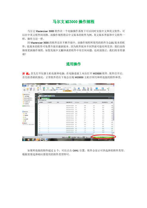
软件打开后,首先检查联机情况,正常软件的右下角会出现MS3000主机序列号和所连接的附件种类。
如果所连接的附件超过1个,可以点击CAN1位置,软件会显示可供选择的附件类型。
根据需要选择相应要使用的附件类型即可。
如果软件上不能正确显示主机和附件序列号(显示为无连接),则表示软件和MS3000仪器之间无通讯,将无法进行测试。
注:仪器主机与电脑间通过USB接口连接。
仪器附件(进样器)本身不带控制电源,电源通过MS3000主机提供。
附件通过控制电缆线接到仪器左侧的CAN接口上,一台主机可以同时连接三台附件(3个CAN接口)。
关机:当测试完成后需要关闭仪器系统时,先关闭软件,再关闭仪器电源。
关软件之前强烈建议先按一下“保存”确认再保存一下数据。
数据保存:MS3000软件默认的是数据后存储方式,即数据测试完成后用户手动按“保存”键保存数据。
为了避免忘记保存数据,也可以启动强制保存模式,即在首个菜单的下拉菜单中选择“选项”菜单,启用“强制保存记录”(前面打勾)。
这样在开始测试时,如果没有打开测试文件软件会自动进入创建测试文件的窗口。
软件界面:软件界面可以按不同方式显示,可以单一显示记录列表或者报告,也可以同时显示记录列表和分析结果界面。
通过“视图”菜单中的“默认”可以回到默认的显示方式。
AS3000基本配置操作表
redundant link #1 IP: 192.168.171.2 MASK:255.255.255.0 redundant link #2 IP: 192.168.172.2 MASK:255.255.255.0
西门子推荐设置, 一个系统内每对 AS3000都使用同样 的设置
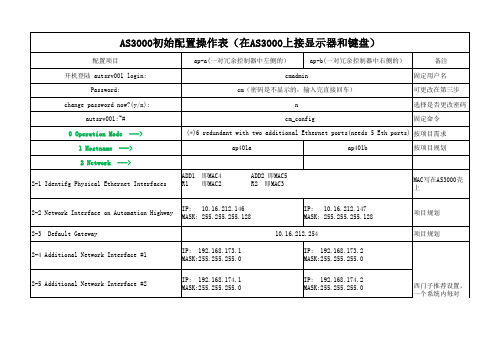
AS3000初始配置操作表(在AS3000上接显示器和键盘)
配置项目 开机登陆 autsrv001 login: Password: change password now?(y/n): autsrv001:~# 0 Operation Mode 1 Hostname 2 Network ---> ap-a(一对冗余控制器中左侧的) cmadmin cm(密码是不显示的,输入完直接回车) n cm_config ap-b(一对冗余控制器中右侧的) 备注 固定用户名 可更改在第三步 选择是否更改密码 固定命令
项目规划
项目规划
项目规划
11 Expert Configuration <Exit>
--->
Do you really want to store the configuration?< Yes > < Yes >
autsrv001:~#ຫໍສະໝຸດ reboot 按Enter键
10.16.210.200 (空格) 10.16.210.201 ---> base-name:winsrv40 IP on the Application Highway: 10.16.212.10 IP on the Automation Highway: 10.16.212.130 the hostname for the remote CM ap401b IP address of the remote CM 10.16.212.147 Remote Redundant Interface #1 192.168.171.2 Remote Redundant Interface #2 192.168.172.2
默耐克系统3000现场调试维修指导
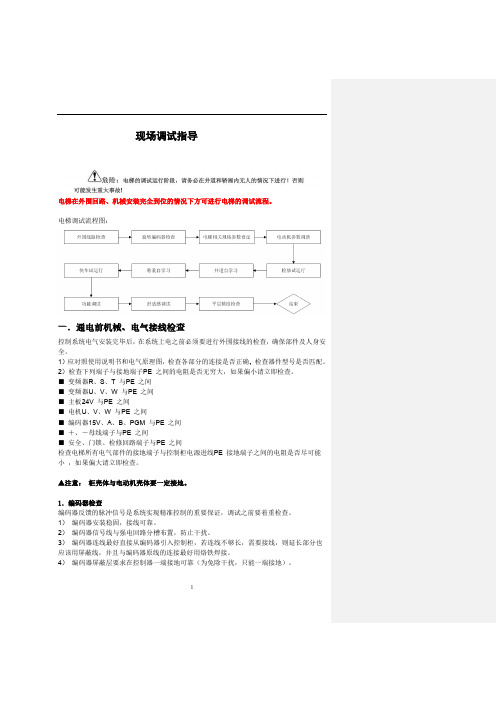
1现场调试指导电梯在外围回路、机械安装完全到位的情况下方可进行电梯的调试流程。
电梯调试流程图:一.通电前机械、电气接线检查控制系统电气安装完毕后,在系统上电之前必须要进行外围接线的检查,确保部件及人身安全。
1)应对照使用说明书和电气原理图,检查各部分的连接是否正确,2)检查下列端子与接地端子PE 之间的电阻是否无穷大,如果偏小请立即检查。
■ 变频器R 、S 、T 与PE 之间■ 变频器U 、V 、W 与PE 之间■ 主板24V 与PE 之间■ 电机U 、V 、W 与PE 之间■ 编码器15V 、A 、B 、PGM 与PE 之间■ +、-母线端子与PE 之间■ 安全、门锁、检修回路端子与PE 之间检查电梯所有电气部件的接地端子与控制柜电源进线PE 接地端子之间的电阻是否尽可能小 ,如果偏大请立即检查。
▲注意: 柜壳体与电动机壳体要一定接地。
1.编码器检查编码器反馈的脉冲信号是系统实现精准控制的重要保证,调试之前要着重检查。
1) 编码器安装稳固,接线可靠。
2) 编码器信号线与强电回路分槽布置,防止干扰。
3) 编码器连线最好直接从编码器引入控制柜,若连线不够长,需要接线,则延长部分也应该用屏蔽线,并且与编码器原线的连接最好用烙铁焊接。
4) 编码器屏蔽层要求在控制器一端接地可靠(为免除干扰,只能一端接地)。
5异步电机调谐流程图永磁同步电机调谐:1) 调谐说明a ) 永磁同步曳引机第一次运行前必须进行磁极位置辨识,否则不能正常使用。
b ) 同步机一体化控制器采用有传感器的闭环矢量控制方式,须确保F0-00 设为1(闭环矢量),且必须正确连接编码器和PG 卡,否则系统将报E20 编码器故障,导致电梯无法运行。
c ) 同步机一体化控制器既可通过操作面板控制方式在电机不带负载的情况下完成电机调谐,也可通过距离控制方式(检修方式)在电机带负载的情况下完成调谐。
d ) 调谐前必须正确设置编码器参数(F1-00、F1-12)和电机铭牌参数(F1-01、F1-02、F1-03F1-04、F1-05)。
Standard3000中文操作手册part1
Standard3000中⽂操作⼿册part13.6. 電箱/控制器3.6.1. 技術資料y尺⼨(寬×⾧×⾼) 205×340×345 mm3000W y輸出功率 1000/2000/50/60Hz,y電源供應 230V,單相電源y溝通介⾯ RS232y LCD顯⽰螢幕 16⾏×40字y參數資料庫32組焊接參數y加⼯資料庫儲存最近25組焊接資料y重量約16 kg本電箱達到下列⼯業安全規定所需標準:y EN 61000-6-4 EMVy EN 61000-6-2 EMVy EN 55011 class A/group 1y Low voltage guidelines 73/23/ EWG4 操作前注意事項4.1. 連接電源與機器各部分請完成以下步驟使機器準備就緒:1.固定壓機上的⼯作檯2.連接壓機與電箱之間的電線注意:電源線請務必接地。
3.將壓機上之電線插⼊電箱背⾯插座:1壓機2雙⼿起動開關3RF (與換能器連接)4電源4.1.1. 主動溝通裝置5RS232插座 (9孔D-sub插座)6數位輸⼊ (25孔D-sub插座,序列埠)7數位輸出 (25孔D-sub插座,序列埠)其他資料請⾒第⼋章”資料分析”,插座配置請⾒第九章”主動溝通與信號傳送”。
4.1.2. 壓縮空氣源:最⼤7 bar;105 psi依下列指⽰轉動壓縮空氣閥(21):4.將壓縮空氣喉(21a)與壓縮空氣供應源連接。
5.將壓縮空氣閥(21)轉⾄⼯作位置。
注意:若輸⼊壓縮空氣壓⼒⼤於7 bar,附加安全氣閥會⾃動開啟釋放過多的空氣壓⼒。
4.1.3. 裝備隔⾳罩SSK-H1ADG電箱電源2數位輸⼊ (25孔D-sub插座,序列埠) 3數位輸出 (25孔D-sub插座,序列埠) 4壓機5雙⼿起動開關6RF (與換能器連接)拆除隔⾳罩後⽅⾯板可調整壓機,卸除或裝備隔⾳罩。
4.2. 操作及顯⽰元件4.2.1. 壓機1 換能器外罩內藏超⾳波發振系統及電源線。
3000主机体中文说明书

1.4.5. 门后撞压危险 • 用制粒室手柄打开制粒室。打开时,不要抓住背后的边缘,因为在制粒室与环
模之间有个压紧点。
1.5. 电气
所附的电气控制图是一建议性的电路,用来控制制粒机的运行。请以适用的电气和安全
标准查看本电路及元器件。
1.6. 头和眼睛的保护
重要信息
在制粒机及其他设备周围工作时,特别是在更换环模和压辊时,要戴安全帽和保护 眼镜。 下落物体或低的顶板会导致受伤。千万要注意保护您的生命与身体。
10 / 52
CPM 无锡
第二部分 安装指导
11 / 52
CPM 无锡
安装指导
2.1.安装地点的计划和设计
2.1.1. 支撑地基 • 地基应由合格的结构工程师来设计。 • 地基应是刚度、非静载荷设计。 • 沿着制粒机两边,跨越制粒机区域较短的一边,深埋数根横梁。 见图 2-1.
图 2.1
• 制粒机的载重量是根据机型和配置而变动的。 见附录中相对于大约重量的一般尺寸图。
安全指导
1.1. 介绍
操作制粒机之前,人员必须被培训正确使用机器。仔细阅读说明书中“安全指导”这一部 分。操作制粒机的培训至少应包括以下内容: 一般安全练习 (详细内容见 1.2) • 操作控制 (见第 3 部分) • 制粒室安全锁定(见 1.4.3) • 紧急制动开关 (见 1.2.3) • 锁定及标记过程 (见 1.2.2) • 警告标志 (见 1.3) • 可能的危险 (见 1.4) • 工具 (见 1.2.4)
2.3.6.安装联轴器防护装置 确保轴和联轴器不与防护装置摩擦。清除旋转零件的速度传感器线。这些线可穿越联轴 器防护装置上的狭缝。
2.4.调质器与喂料器的安装(略) 2.5.电气安装
- 1、下载文档前请自行甄别文档内容的完整性,平台不提供额外的编辑、内容补充、找答案等附加服务。
- 2、"仅部分预览"的文档,不可在线预览部分如存在完整性等问题,可反馈申请退款(可完整预览的文档不适用该条件!)。
- 3、如文档侵犯您的权益,请联系客服反馈,我们会尽快为您处理(人工客服工作时间:9:00-18:30)。
MACAS3000门禁管理系统Macas3000 Management System操作员手册Operating Instructions适用于V1.0版本录MD3-S0784-0910-V1.7 版权所有,翻印必究 ! 安装、调试、操作之前,请仔细,阅读资料。
否则,因操作不当引起设备或系统损坏,责任自负!更改记录目录1安装配置 (5)1.1门禁监视终端(A CCESS M ONITOR) (5)1.1.1安装 (5)1.1.2配置 (5)1.2刷卡显像终端(E NTRY D ISPLAY) (6)1.3巡更系统 (7)1.3.1巡更服务程序(TourServer ) (7)1.3.1.1安装 (7)1.3.1.2配置 (7)1.3.2巡更终端(Tourmonitor) (7)1.3.2.1巡更程序导入服务(TourImporter) (8)1.4液晶读卡器配置软件(READERCONFIGURA TOR) (8)1.5键盘密码重置器(P ASSWORD R ESETTER) (9)2卸载 (9)3功能介绍 (10)3.1门禁监视终端(A CCESS M ONITOR) (10)3.1.1登录 (10)3.1.2初始化设置 (10)3.1.3菜单 (10)3.1.4文件菜单 (10)3.1.5地图菜单 (10)3.1.6高级菜单 (11)3.1.6.1参数设置 (11)3.1.6.2视频设置 (13)3.1.6.3所有门动作 (13)3.1.6.4事件查询 (13)3.1.6.5事件过滤设置 (14)3.1.7便捷任务管理 (14)3.1.8其他菜单 (15)3.1.9帮助菜单 (16)3.1.10新建、编辑、删除地图 (17)3.1.10.1新建地图 (17)3.1.10.2删除地图 (19)3.1.11设备控制板 (19)3.1.11.1门禁机动作 (19)3.1.11.2报警点动作 (19)3.1.11.3继电器动作 (20)3.1.11.4布防和报警状态 (20)3.1.11.5辅助输入输出状态 (20)3.1.12设备信息 (21)3.1.13图标信息 (21)3.2巡更终端(T OURMONITOR) (22)3.3刷卡显像终端(E NTRY D ISPLAY) (22)3.3.1配置系统参数 (22)3.3.2配置显像设备 (22)3.3.3配置显像模板 (23)3.4液晶读卡器配置器 (27)3.5键盘密码重置器(P ASSWORD R ESETTER) (28)3.6巡更终端(T OURMONITOR) (29)3.7安装T OUR M ONITOR I NSTALL.EXE (29)3.8登录 (31)3.9菜单 (32)3.9.1文件菜单 (32)3.9.2线路信息菜单 (32)3.9.3高级 (33)1安装配置1.1门禁监视终端(AccessMonitor)1.1.1安装✓门禁监视终端是门吉利Macas3000综合保安系统的必需客户端工作站,安装程序集成在Macas3000的安装包中。
✓将Macas3000的安装盘放入光驱并浏览,我们可以看到类似图(3.1-1)所示的内容:图(1.1-1)◆首先,安装工作环境●双击macas3000的安装程序,在【工作环境安装】中选择“安装MYSQL数据库服务器”、“微软.NET运行环境”;●如果与服务器安装在同一台计算机中,还需要安装“JDK java运行环境”;●具体的安装介绍请参阅管理员手册相关内容。
◆其次,安装一卡通数据库●如果监视终端独立安装在某台计算机中,当安装程序运行到“安装一卡通数据库”时选择[不安装(跳过)]。
●具体的安装介绍请参阅管理员手册相关内容。
◆再次,安装服务器部分●如果监视终端独立安装在某台计算机中,当安装程序运行到“安装服务器部分”时不选择任何一个服务器并点击[下一步]进入到客户端部分的安装选择界面。
●具体的安装介绍请参阅管理员手册相关内容。
◆最后,安装门禁监视终端●在客户端部分将“门禁监视终端”选中并点[下一步]安装监视终端;●门禁系统对客户端工作站的安装目录没有特殊要求,用户可以选择默认路径“D:\ProgramFiles\Melucky”也可以自定义安装路径;●如果只是安装客户端工作站,那么,安装程序安装完客户端进入到“WEB服务器配置”部分时,可以选择[跳过本页]结束安装操作。
1.1.2配置✓在macas3000的WEB管理系统中给监视终端授权并增加合法的监视员。
✓登录macas3000的WEB管理页面,在【基本设置部分】选择【服务站部分】的【监视终端设置】中增加监视终端并指定归属于哪个服务PC(本地管理系统),填写内容如下图:图(1.1-2)✓在【系统用户管理】的【监视操作员管理】中增加监视操作员并授权:图(1.1-3)✓权限包括:修改地图的权限、操作设备的权限、可监视的服务PC的范围等。
1.2刷卡显像终端(EntryDisplay)✓特殊订制产品,有独立的安装程序。
✓双击刷卡显像安装程序,进入到安装首页,请仔细阅读协议内容并做选择:选择【下一步】继续安装操作,选择【取消】退出安装程序。
✓与监视终端类似,用户可以自定义安装路径,也可以按默认路径安装;✓若安装正确,程序结束时自动出现安装完毕提示窗口,用户点【完成】结束安装。
图(1.2-1)1.3巡更系统◆特殊订制产品,有独立的安装程序。
◆包括:巡更服务程序(TourServer)、巡更监视终端(Tourmonitor)、巡更程序导入服务(TourImporter)等;1.3.1巡更服务程序(TourServer )1.3.1.1安装◆双击刷卡显像安装程序,进入到安装首页,请仔细阅读协议内容并做选择:选择【下一步】继续安装操作,选择【取消】退出安装程序。
◆与监视终端类似,用户按默认路径“D:\usr\local\melucky\macas3000LC”安装;◆若安装正确,程序结束时自动出现安装完毕的提示窗口,用户点【完成】结束安装。
1.3.1.2配置◆为了在启动本地服务的同时可以启动巡更服务程序,需要配置位于D:\usr\local\melucky\macas3000LC\startMACAS3000LC.bat文件;图(1.3-1)◆增加图中红色方框中的语句并保存,重新启动巡更服务程序即可。
1.3.2巡更终端(Tourmonitor)◆双击刷卡显像安装程序,进入到安装首页,请仔细阅读协议内容并做选择:选择【下一步】继续安装操作,选择【取消】退出安装程序。
◆与监视终端类似,用户可以自定义安装路径,也可以按默认路径安装;◆若安装正确,程序结束时自动出现安装完毕的提示窗口,用户点【完成】结束安装。
◆登录巡更终端需要合法身份:在aclocalmanager(本地服务管理的WEB页面)的【系统用户管理】---【巡更监视员管理】中增加合法的监视员信息1.3.2.1巡更程序导入服务(TourImporter)◆巡更导入程序服务的目的是把第三方巡更设备的原始巡更数据导入到门吉利一卡通数据库中,以备门吉利巡更系统统计管理;适用于使用第三方巡更设备的用户。
◆安装过程请参考巡更服务程序的安装介绍;◆安装程序为;◆请用户务必安装于本地服务系统macas3000lc路径下,默认路径为D:\usr\local\ melucky\macas3000LC\TourImporter;◆请在有关人员的指导下配置相关的配置文件tourimporter.properties(默认的安装路径为D:\usr\local\melucky\macas3000LC\TourImporter\conf:图(1.3-2)1.4液晶读卡器配置软件(readerconfigurator)✓特殊订制产品,专为macas3000系统中使用的液晶读卡器的配置软件有独立的安装程序。
✓安装过程与门禁监视终端类似,安装程序为ReaderConfigurator Install.EXE;✓双击进入到协议界面,请仔细阅读协议内容,同意安装请点击“下一步”,进入到安装目录的设置界面;✓液晶读卡器的配置软件是独立的硬件设备参数设置的工具软件,没有安装路径的限制,用户可自行设置;✓指定安装路径后可以按安装程序的引导安装,直至出现安装成功的确定提示窗口(如下图)时点击“完成”结束安装。
图(1.4-1)1.5键盘密码重置器(PasswordResetter)✓特殊订制产品,专为初始化macas3000系统中使用的密码键盘控制器的密码的配置软件;✓有独立的安装程序。
✓安装过程与门禁监视终端类似,安装程序为PasswordResetterInstall.EXE;✓双击进入到协议界面,请仔细阅读协议内容,同意安装请点击“下一步”,进入到安装目录的设置界面;✓密码键盘控制器的重置软件是独立的初始化硬件备参数的工具软件,没有安装路径的限制,用户可自行设置;✓指定安装路径后可以按安装程序的引导安装,直至出现安装成功的确定提示窗口(类似于图1.4-1)时点击“完成”结束安装。
2卸载✓直接删除各个终端的安装目录下的对应文件夹即可,如卸载门禁监视终端,直接删除“D:\Program Files\Melucky\AccessMonitor”✓删除计算机操作系统的桌面上的快捷图标如“MACAS3000门吉利门禁监视终端”:✓删除开始菜单相关条目,如卸载门禁监视终端,选择“开始”菜单中“本地管理系统”下的“门吉利门禁监视终端”的右键菜单中的“删除”并执行即可。
图(1.6-1)3功能介绍3.1门禁监视终端(AccessMonitor)✓门禁监视(AccessMonitor)负责实时反馈各个门禁设备的运行状态、故障及时告警、手动操作门禁设备的设防、撤防、取消报警、门动作等。
3.1.1登录✓按照中央门禁管理系统中的有效终端监视员的用户名和登录密码登录监视终端,如下图所示:图(2.1-1)3.1.2初始化设置✓增加需要监视的本地服务器工作站:高级菜单下的参数设置-工作站设置。
✓设置动态地图并在此地图上添加相应门禁设备:地图菜单。
✓可设置多幅动态地图和设备。
3.1.3菜单3.1.4文件菜单●修改密码:可随时修改终端密码,无须登陆服务器修改。
●注销:可使监视终端重新登陆,节省了不必要的时间。
●锁定:锁定界面,使其无法在此界面进行操作,输入密码解锁。
●退出:点此选项可直接退出。
3.1.5地图菜单●自动:当有多幅地图的时候,选择自动模式,地图会按照顺序自动变换地图。
●手动:当选择手动模式时,根据自己手动点击显示哪幅地图。
●优先:选择优先模式,表示哪幅地图优先被显示。
●图例:设备的各种状态的图例,点击如下图:3.1.6高级菜单3.1.6.1参数设置◆参数设置中分为工作站设置及基本参数设置两部分。